User login
Emergency Ultrasound: Deep Vein Thrombosis
Femoral and Saphenous Vein
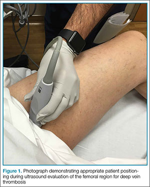
After the appropriate positioning has been achieved, the clinician should identify the common femoral vein and artery, and then slide the probe toward the head or feet until the saphenous vein, which empties into the common femoral vein, is identified 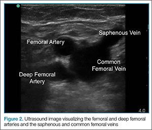
The clinician should take care not to apply too much pressure with the probe as this will compress the saphenous vein; therefore, it is important to use a light touch to ensure proper visualization. Once this key region is identified, the clinician should then use the probe to apply pressure to the vessels. The saphenous vein should compress completely upon application of sufficient pressure to the artery. In a normal vein, the anterior and posterior walls should touch and completely obliterate the lumen of the vein. When a clot is present, the walls of the vein will remain separated (Figure 3). A thrombus can be bright on ultrasound, but some DVTs may appear completely black. In some cases, a lack of compressibility may be the only tip-off to the presence of clot. 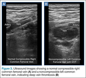
After fully evaluating the saphenous vein, the clinician should move the probe toward the feet, keeping the vessels centered in the image, while at the same time applying serial compression approximately every centimeter. As the probe is moved distally, the artery will typically bifurcate first and then the vein will bifurcate into the femoral and deep femoral branches. The femoral vein should be followed until it “dives” into the adductor canal.
Popliteal Region
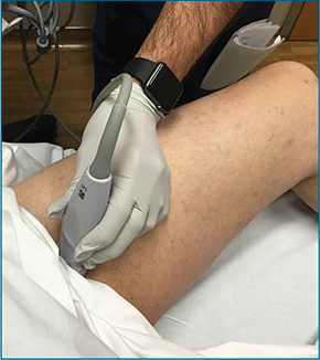
The second zone of the examination is in the popliteal region. It can be helpful to prop the foot up, or hang the foot off the bed to improve access to this region (Figure 4). Similar to the femoral region, maximizing your depth and then decreasing it once the vessels are identified can help to ensure that you are not mistaking superficial vessels 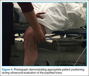
Common Pitfalls
The main pitfall to performing a DVT study is failing to identify the correct vessels. It is important to identify both the artery and vein running together to ensure that the correct location. In larger patients, the relatively shallow depth of the high-frequency 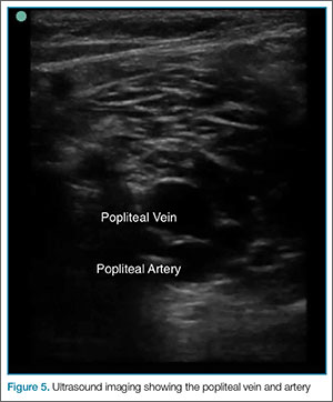
Another common pitfall to keep in mind is that lymph nodes can often be mistaken for clot (Figure 6). A lymph node may be distinguished from a clot by sliding the probe up and down the patient’s leg—lymph nodes will appear as discrete structures, continuous like vasculature. It is essential to evaluate the length of the common femoral, the femoral, and popliteal veins visualized as a recent study by Adhikari et al1 showed that two-point compression studies can miss up to 6% of isolated clots.
Summary
With practice, POC compression ultrasonography of the lower extremities can be used to quickly rule in the diagnosis DVT. Proper patient and probe positioning, as well as the application of appropriate probe pressure at different stages of the examination are essential to accurately visualize and assess the femoral, saphenous, and popliteal veins for the presence of a thrombus.
For a video and more information on performing this scan: 
Dr Meer is an assistant professor and director of emergency ultrasound, department of emergency medicine, Emory University School of Medicine, Atlanta, Georgia. Dr Beck is an assistant professor, department of emergency medicine, Emory University School of Medicine, Atlanta, Georgia. Dr Taylor is an assistant professor and director of postgraduate medical education, department of emergency medicine, Emory University School of Medicine, Atlanta, Georgia.
- Emergency Ultrasound: Deep Vein Thrombosis
- Adhikari S, Zeger W, Thom C, Fields JM. Isolated deep venous thrombosis: implications for 2-point compression ultrasonography of the lower extremity. Ann Emerg Med. 2015;66(3):262-266.
Femoral and Saphenous Vein
After the appropriate positioning has been achieved, the clinician should identify the common femoral vein and artery, and then slide the probe toward the head or feet until the saphenous vein, which empties into the common femoral vein, is identified
The clinician should take care not to apply too much pressure with the probe as this will compress the saphenous vein; therefore, it is important to use a light touch to ensure proper visualization. Once this key region is identified, the clinician should then use the probe to apply pressure to the vessels. The saphenous vein should compress completely upon application of sufficient pressure to the artery. In a normal vein, the anterior and posterior walls should touch and completely obliterate the lumen of the vein. When a clot is present, the walls of the vein will remain separated (Figure 3). A thrombus can be bright on ultrasound, but some DVTs may appear completely black. In some cases, a lack of compressibility may be the only tip-off to the presence of clot.
After fully evaluating the saphenous vein, the clinician should move the probe toward the feet, keeping the vessels centered in the image, while at the same time applying serial compression approximately every centimeter. As the probe is moved distally, the artery will typically bifurcate first and then the vein will bifurcate into the femoral and deep femoral branches. The femoral vein should be followed until it “dives” into the adductor canal.
Popliteal Region
The second zone of the examination is in the popliteal region. It can be helpful to prop the foot up, or hang the foot off the bed to improve access to this region (Figure 4). Similar to the femoral region, maximizing your depth and then decreasing it once the vessels are identified can help to ensure that you are not mistaking superficial vessels
Common Pitfalls
The main pitfall to performing a DVT study is failing to identify the correct vessels. It is important to identify both the artery and vein running together to ensure that the correct location. In larger patients, the relatively shallow depth of the high-frequency
Another common pitfall to keep in mind is that lymph nodes can often be mistaken for clot (Figure 6). A lymph node may be distinguished from a clot by sliding the probe up and down the patient’s leg—lymph nodes will appear as discrete structures, continuous like vasculature. It is essential to evaluate the length of the common femoral, the femoral, and popliteal veins visualized as a recent study by Adhikari et al1 showed that two-point compression studies can miss up to 6% of isolated clots.
Summary
With practice, POC compression ultrasonography of the lower extremities can be used to quickly rule in the diagnosis DVT. Proper patient and probe positioning, as well as the application of appropriate probe pressure at different stages of the examination are essential to accurately visualize and assess the femoral, saphenous, and popliteal veins for the presence of a thrombus.
For a video and more information on performing this scan:
Dr Meer is an assistant professor and director of emergency ultrasound, department of emergency medicine, Emory University School of Medicine, Atlanta, Georgia. Dr Beck is an assistant professor, department of emergency medicine, Emory University School of Medicine, Atlanta, Georgia. Dr Taylor is an assistant professor and director of postgraduate medical education, department of emergency medicine, Emory University School of Medicine, Atlanta, Georgia.
- Emergency Ultrasound: Deep Vein Thrombosis
- Adhikari S, Zeger W, Thom C, Fields JM. Isolated deep venous thrombosis: implications for 2-point compression ultrasonography of the lower extremity. Ann Emerg Med. 2015;66(3):262-266.
- Emergency Ultrasound: Deep Vein Thrombosis
- Adhikari S, Zeger W, Thom C, Fields JM. Isolated deep venous thrombosis: implications for 2-point compression ultrasonography of the lower extremity. Ann Emerg Med. 2015;66(3):262-266.
Case Report: Perianal Streptococcal Infection
Case
The mother of a 3-year-old boy presented her son to the ED for evaluation after she noticed peeling of the skin in his perianal region. She stated that the peeling had started 1 day prior to presentation. Two days earlier, the mother had brought the same patient to the ED for evaluation of a fever, sore throat, and a slight rash over his face. The boy’s vital signs at the initial presentation were: temperature, 101.8°F; heart rate, 102 beats/minute; and respiratory rate, 28 breaths/minute. Oxygen saturation was 98% on room air.
During this first visit, the mother denied the child having had any fever, chills, headache, sore throat, facial rash, joint pain, or pain on defecation. He had no significant medical history and no known drug allergies. After examination, a throat culture was taken, and the patient was given acetaminophen and discharged home with a diagnosis of viral syndrome.
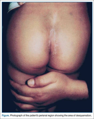
At the second presentation, physical examination revealed a well-developed child in no distress. The examination was negative except for a 4 x 2 cm area of desquamation present over the perianal region (Figure).
The area of desquamation was dry, mildly erythematous without discharge, and nontender. The patient’s vital signs at this presentation were stable, and he was afebrile. The remaining physical examination findings were normal. The throat culture taken during the first ED presentation was reported as negative. A perianal swab was sent for culture and sensitivity. This was later reported to be positive for group A β-hemolytic streptococci (GABHS), which is sensitive to penicillin. The patient was discharged home in the care of his mother with a prescription of penicillin. A 10-day follow-up showed complete resolution of the skin rash.
Discussion
The rash in this case was most likely the result of scarlet fever with an unusual presentation of PSD; the signs and symptoms of which include perianal erythema, itching, rectal pain, sometimes blood-streaked stools, rectal bleeding, irritation or pruritus, tissue loss and exudation, secondary constipation, and cellulitis. Perianal streptococcal dermatitis has also been described in the adult literature.2 As with pediatric cases, PSD in adults is usually caused by GABHS.
Evaluation and Diagnosis
A rapid streptococcal test of suspicious areas can confirm the diagnosis. Fever, sore throat, and arthralgia are rare; however, culture from the perianal region grows GABHS. Titers are usually not elevated in laboratory evaluation. A routine skin culture is an alternative diagnostic aid.
Brilliant2 described the bright red color of PSD as a sharply demarcated rash that is caused by GABHS. As previously stated, symptoms include perianal rash, itching, and rectal pain; blood-streaked stools may also be seen in one-third of patients. It primarily occurs in children between 6 months and 10 years of age and is often misdiagnosed and treated inappropriately.3
Prompt diagnosis of GABHS is important. If untreated, it can cause serious systemic infections, especially in elderly and in newborn patients. Treatment with antibiotics resolves the condition in the majority of patients.2 In the acute stage, a white pseudomembrane may be present. As the rash becomes more chronic, the perianal eruption may consist of painful fissures, a dry mucoid discharge, or psoriasiform plaques. Perianal dermatitis can also be caused by Staphylococcus aureus or Candida. Confirmation of the diagnosis is accomplished by culturing a moderate-to-heavy growth of GABHS on 5% sheep-blood agar.
Treatment
A 10-day course of oral penicillin produces resolution of the dermatitis and other symptoms in most patients, but a relapse rate as high as 39% has been reported. Other treatment plans include amoxicillin, 40 mg/kg per day, divided into three doses, and/or topical applications of mupirocin 2% three times per day for 10 days. Penicillin, clindamycin phosphate, and erythromycin have also been used.
Although penicillin is generally recommended for treatment of GABHS infection, amoxicillin is often better tolerated in the pediatric population due to its superior palatability. Early antibiotic treatment causes a dramatic and rapid improvement of symptoms. However, according to Olson et al,4 PSD initially treated with amoxicillin or penicillin is consistently associated with a high risk of clinical recurrence. Whether treatment with a β-lactamase–resistant agent reduces this risk is uncertain.
Conclusion
This case represents an unusual presentation of scarlet fever manifesting as perianal dermatitis caused by GABHS. Although more common in the pediatric population, adult cases have been documented in the literature. As this case illustrates, early recognition and treatment with penicillin (or amoxicillin) produces rapid improvement and resolution of symptoms.
Dr Nibhanipudi is a professor of clinical emergency medicine at New York Medical College - Metropolitan Hospital Center, New York.
- Case Report: Perianal Streptococcal Infection
- Landolt M, Heininger U. Prevalence of perianal streptococcal dermatitis in children and adolescents [in German]. Praxis (Bern 1994). 2005;94(38):1467-1471.
- Kahlke V, Jongen J, Peleikis HG, Herbst RA. Perianal streptococcal dermatitis in adults: its association with pruritic anorectal diseases is mainly caused by group B Streptococci. Colorectal Dis. 2013;15(5):602-607.
- Brilliant LC. Perianal streptococcal dermatitis. Am Fam Physician. 2000;61(2):391-393.
- Olson D, Edmonson MB. Outcomes in children treated for perineal group A beta-hemolytic streptococcal dermatitis. Pediatr Infect Dis J. 2011;30(11):933-936.
Case
The mother of a 3-year-old boy presented her son to the ED for evaluation after she noticed peeling of the skin in his perianal region. She stated that the peeling had started 1 day prior to presentation. Two days earlier, the mother had brought the same patient to the ED for evaluation of a fever, sore throat, and a slight rash over his face. The boy’s vital signs at the initial presentation were: temperature, 101.8°F; heart rate, 102 beats/minute; and respiratory rate, 28 breaths/minute. Oxygen saturation was 98% on room air.
During this first visit, the mother denied the child having had any fever, chills, headache, sore throat, facial rash, joint pain, or pain on defecation. He had no significant medical history and no known drug allergies. After examination, a throat culture was taken, and the patient was given acetaminophen and discharged home with a diagnosis of viral syndrome.
At the second presentation, physical examination revealed a well-developed child in no distress. The examination was negative except for a 4 x 2 cm area of desquamation present over the perianal region (Figure).
The area of desquamation was dry, mildly erythematous without discharge, and nontender. The patient’s vital signs at this presentation were stable, and he was afebrile. The remaining physical examination findings were normal. The throat culture taken during the first ED presentation was reported as negative. A perianal swab was sent for culture and sensitivity. This was later reported to be positive for group A β-hemolytic streptococci (GABHS), which is sensitive to penicillin. The patient was discharged home in the care of his mother with a prescription of penicillin. A 10-day follow-up showed complete resolution of the skin rash.
Discussion
The rash in this case was most likely the result of scarlet fever with an unusual presentation of PSD; the signs and symptoms of which include perianal erythema, itching, rectal pain, sometimes blood-streaked stools, rectal bleeding, irritation or pruritus, tissue loss and exudation, secondary constipation, and cellulitis. Perianal streptococcal dermatitis has also been described in the adult literature.2 As with pediatric cases, PSD in adults is usually caused by GABHS.
Evaluation and Diagnosis
A rapid streptococcal test of suspicious areas can confirm the diagnosis. Fever, sore throat, and arthralgia are rare; however, culture from the perianal region grows GABHS. Titers are usually not elevated in laboratory evaluation. A routine skin culture is an alternative diagnostic aid.
Brilliant2 described the bright red color of PSD as a sharply demarcated rash that is caused by GABHS. As previously stated, symptoms include perianal rash, itching, and rectal pain; blood-streaked stools may also be seen in one-third of patients. It primarily occurs in children between 6 months and 10 years of age and is often misdiagnosed and treated inappropriately.3
Prompt diagnosis of GABHS is important. If untreated, it can cause serious systemic infections, especially in elderly and in newborn patients. Treatment with antibiotics resolves the condition in the majority of patients.2 In the acute stage, a white pseudomembrane may be present. As the rash becomes more chronic, the perianal eruption may consist of painful fissures, a dry mucoid discharge, or psoriasiform plaques. Perianal dermatitis can also be caused by Staphylococcus aureus or Candida. Confirmation of the diagnosis is accomplished by culturing a moderate-to-heavy growth of GABHS on 5% sheep-blood agar.
Treatment
A 10-day course of oral penicillin produces resolution of the dermatitis and other symptoms in most patients, but a relapse rate as high as 39% has been reported. Other treatment plans include amoxicillin, 40 mg/kg per day, divided into three doses, and/or topical applications of mupirocin 2% three times per day for 10 days. Penicillin, clindamycin phosphate, and erythromycin have also been used.
Although penicillin is generally recommended for treatment of GABHS infection, amoxicillin is often better tolerated in the pediatric population due to its superior palatability. Early antibiotic treatment causes a dramatic and rapid improvement of symptoms. However, according to Olson et al,4 PSD initially treated with amoxicillin or penicillin is consistently associated with a high risk of clinical recurrence. Whether treatment with a β-lactamase–resistant agent reduces this risk is uncertain.
Conclusion
This case represents an unusual presentation of scarlet fever manifesting as perianal dermatitis caused by GABHS. Although more common in the pediatric population, adult cases have been documented in the literature. As this case illustrates, early recognition and treatment with penicillin (or amoxicillin) produces rapid improvement and resolution of symptoms.
Dr Nibhanipudi is a professor of clinical emergency medicine at New York Medical College - Metropolitan Hospital Center, New York.
- Case Report: Perianal Streptococcal Infection
- Landolt M, Heininger U. Prevalence of perianal streptococcal dermatitis in children and adolescents [in German]. Praxis (Bern 1994). 2005;94(38):1467-1471.
- Kahlke V, Jongen J, Peleikis HG, Herbst RA. Perianal streptococcal dermatitis in adults: its association with pruritic anorectal diseases is mainly caused by group B Streptococci. Colorectal Dis. 2013;15(5):602-607.
- Brilliant LC. Perianal streptococcal dermatitis. Am Fam Physician. 2000;61(2):391-393.
- Olson D, Edmonson MB. Outcomes in children treated for perineal group A beta-hemolytic streptococcal dermatitis. Pediatr Infect Dis J. 2011;30(11):933-936.

Patient-Directed Valgus Stress Radiograph of the Knee: A New and Novel Technique
Medial-compartment partial knee arthroplasty (unicompartmental replacement) is an accepted surgical intervention for anteromedial osteoarthritis of the knee.1 The radiographic investigations required in the workup of these patients should include weight-bearing standing anteroposterior (AP), lateral, and sunrise (Merchant) views, as well as a valgus stress AP radiograph to assess the functionality of the lateral compartment. The method of properly obtaining the valgus stress film has been well described by the Oxford Group.2 Its recommended radiographic technique requires that a surgeon or a radiologic technologist perform the valgus stress maneuver, manually, while another technologist shoots the film. The 2 consequences of this technique are that it requires 2 individuals to obtain the film, and it subjects the individual who is applying the stress to some level of radiation exposure, which is undesirable. Because of this and the time inconvenience, many surgeons omit the valgus stress radiograph, which can lead to the adverse outcome of missing a lateral compartment that is functionally incompetent, resulting in the potential for early lateral compartment progression of osteoarthritis and the need for revision surgery, usually to a total knee arthroplasty.
In an attempt to mitigate these barriers to obtaining the necessary valgus stress radiograph, Dr. Mauerhan’s team developed a technique that could be done with the assistance of the patient and would require only 1 technologist to perform. Additionally, this project was a quality improvement initiative, because it lowered radiation exposure to all personnel involved in obtaining the correct films.
Materials and Methods
We initiated the project using weight-bearing strategies to impart the valgus stress view of the knee. After trying several different wedges and blocks, and varying patient instructions, we realized a different approach to this problem would be required to find an acceptable solution. We redirected our efforts to effectively performing the stress view with the patient in a supine position on the radiograph table. Ultimately, we decided that a much stiffer wedge and a denser object to squeeze would facilitate obtaining a proper film. Considering all available options, a youth size 4 soccer ball (diameter, 11 in) was introduced along with a slightly larger positioning wedge. The soccer ball was wrapped with 4-in Coban wrap (3M) to create a nonslip surface. This change in patient positioning, along with a standardized 7º to 10º cephalic radiographic tube angulation, helped to correct issues with tibial plateau visualization. Once these changes were enacted, we obtained fairly consistent positive results, and we instituted this patient-directed valgus stress view of the knee, along with a manual valgus stress view for comparison.
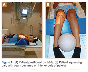
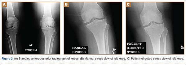
The protocol for obtaining the patient-directed valgus stress view of the knee is as follows: The patient lays supine with a dense 45º spine-positioning wedge (Burlington Medical Supplies) placed under both knees and the patient’s heels on the examining table. The radiographic tube is angled cephalad 7º to 10º centered on the inferior pole of the patella, using a 40-in source to image-receptor distance, collimated to part; the image receptor is placed under the affected knee, below the positioning wedge. The affected knee is rotated to the “true” AP position (the patella will be centered between the femoral condyles on the AP exposure), and the ball is placed between the patient’s legs just above the ankle joint. The technologist demonstrates to the patient how to squeeze the ball while maintaining contact of heels with the table. The technologist can exit the room and obtain the exposure, which is taken while the patient is squeezing the ball, as shown in Figures 1A and 1B. Examples of the standing AP, manual stress, and patient-directed valgus radiographs are shown in Figures 2A-2C. The entire technique is demonstrated in the Video.

Results
During the 9 months of this quality improvement project, 78 examinations were performed. Five studies did not show complete correction of the varus deformity. Of these, 3 showed complete correction on a manual valgus stress radiograph, and 2 did not, contraindicating the use of partial knee replacement. Three patients displayed collapse of the lateral compartment, indicating a nonfunctional lateral compartment, and, therefore, were also a contraindication to partial knee arthroplasty. The remaining 70 patients had identical radiographic results with both the manual and patient-directed valgus stress tests. There was no instance of examination failure or need to repeat as a result of difficulty of the examination for the patient. Repeat films because of positioning errors were very rare, usually early in the learning curve, and no more prevalent than when using the manual stress method. The technique was reproducible and easy to teach and adopt.
Discussion
In total, 73 patients (93.5%) with the patient-directed stress film showed the desired result, either correction of the medial compartment narrowing in conjunction with an intact lateral compartment or narrowing of the lateral compartment. Of the 5 patients (6.5%) whose patient-directed stress films did not show correction of the varus deformity, 3 patients displayed correction with a manually applied stress radiograph and 2 did not. Based on this observation, our recommendation would be for those patients who do not show adequate correction on the patient-directed stress radiograph to have a manual examination to establish the presence or absence of the desired correction.
Performing a valgus stress radiograph is an integral part of the investigation to determine if the patient is an appropriate candidate for partial knee arthroplasty.3 The historical, manually performed valgus stress radiograph requires 2 individuals, 1 to apply the stress with the patient on the table and 1 to shoot the exposure. For the individual or individuals applying this stress, there is an increased radiation exposure that would be undesirable over a long career. The authors developed a new technique using a commercially available spinal positioning wedge and 11-in youth soccer ball wrapped with Coban wrap, as described, which is economical and easy to obtain and use in the clinical setting. We believe this cost-effective method will offer surgeons who perform partial knee arthroplasty a novel method to obtain the important information gleaned from the valgus stress radiograph and to improve surgical outcomes through the preoperative assessment of the lateral compartment. Additionally, as a quality and safety improvement initiative, we believe this technique will reduce radiographic exposure for those performing these studies, and, because the examination can be carried out by a single technologist, it will significantly improve efficiency in the radiology suite.
Conclusion
We have developed a new method of obtaining the important valgus stress radiograph as part of the workup of patients with medial-compartment osteoarthritis of the knee. The technique can be performed with easily obtainable, commercially available products and is reliable 93.5% of the time. It also adds to the efficiency of the radiology suite and reduces radiographic exposure for technologists.
1. White SH, Ludkowski PF, Goodfellow JW. Anteromedial osteoarthritis of the knee. J Bone Joint Surg Br. 1991;73(4):582-586.
2. Goodfellow JW, O’Conner JJ, Dodd CA, Murray DW. Unicompartmental Arthroplasty with the Oxford Knee. Woodeaton, Oxford, England: Goodfellow Publishers Limited; 2006:38-39.
3. Gibson PH, Goodfellow JW. Stress radiography in degenerative arthritis of the knee. J Bone Joint Surg Br. 1986;68(4):608-609.
Medial-compartment partial knee arthroplasty (unicompartmental replacement) is an accepted surgical intervention for anteromedial osteoarthritis of the knee.1 The radiographic investigations required in the workup of these patients should include weight-bearing standing anteroposterior (AP), lateral, and sunrise (Merchant) views, as well as a valgus stress AP radiograph to assess the functionality of the lateral compartment. The method of properly obtaining the valgus stress film has been well described by the Oxford Group.2 Its recommended radiographic technique requires that a surgeon or a radiologic technologist perform the valgus stress maneuver, manually, while another technologist shoots the film. The 2 consequences of this technique are that it requires 2 individuals to obtain the film, and it subjects the individual who is applying the stress to some level of radiation exposure, which is undesirable. Because of this and the time inconvenience, many surgeons omit the valgus stress radiograph, which can lead to the adverse outcome of missing a lateral compartment that is functionally incompetent, resulting in the potential for early lateral compartment progression of osteoarthritis and the need for revision surgery, usually to a total knee arthroplasty.
In an attempt to mitigate these barriers to obtaining the necessary valgus stress radiograph, Dr. Mauerhan’s team developed a technique that could be done with the assistance of the patient and would require only 1 technologist to perform. Additionally, this project was a quality improvement initiative, because it lowered radiation exposure to all personnel involved in obtaining the correct films.
Materials and Methods
We initiated the project using weight-bearing strategies to impart the valgus stress view of the knee. After trying several different wedges and blocks, and varying patient instructions, we realized a different approach to this problem would be required to find an acceptable solution. We redirected our efforts to effectively performing the stress view with the patient in a supine position on the radiograph table. Ultimately, we decided that a much stiffer wedge and a denser object to squeeze would facilitate obtaining a proper film. Considering all available options, a youth size 4 soccer ball (diameter, 11 in) was introduced along with a slightly larger positioning wedge. The soccer ball was wrapped with 4-in Coban wrap (3M) to create a nonslip surface. This change in patient positioning, along with a standardized 7º to 10º cephalic radiographic tube angulation, helped to correct issues with tibial plateau visualization. Once these changes were enacted, we obtained fairly consistent positive results, and we instituted this patient-directed valgus stress view of the knee, along with a manual valgus stress view for comparison.
The protocol for obtaining the patient-directed valgus stress view of the knee is as follows: The patient lays supine with a dense 45º spine-positioning wedge (Burlington Medical Supplies) placed under both knees and the patient’s heels on the examining table. The radiographic tube is angled cephalad 7º to 10º centered on the inferior pole of the patella, using a 40-in source to image-receptor distance, collimated to part; the image receptor is placed under the affected knee, below the positioning wedge. The affected knee is rotated to the “true” AP position (the patella will be centered between the femoral condyles on the AP exposure), and the ball is placed between the patient’s legs just above the ankle joint. The technologist demonstrates to the patient how to squeeze the ball while maintaining contact of heels with the table. The technologist can exit the room and obtain the exposure, which is taken while the patient is squeezing the ball, as shown in Figures 1A and 1B. Examples of the standing AP, manual stress, and patient-directed valgus radiographs are shown in Figures 2A-2C. The entire technique is demonstrated in the Video.
Results
During the 9 months of this quality improvement project, 78 examinations were performed. Five studies did not show complete correction of the varus deformity. Of these, 3 showed complete correction on a manual valgus stress radiograph, and 2 did not, contraindicating the use of partial knee replacement. Three patients displayed collapse of the lateral compartment, indicating a nonfunctional lateral compartment, and, therefore, were also a contraindication to partial knee arthroplasty. The remaining 70 patients had identical radiographic results with both the manual and patient-directed valgus stress tests. There was no instance of examination failure or need to repeat as a result of difficulty of the examination for the patient. Repeat films because of positioning errors were very rare, usually early in the learning curve, and no more prevalent than when using the manual stress method. The technique was reproducible and easy to teach and adopt.
Discussion
In total, 73 patients (93.5%) with the patient-directed stress film showed the desired result, either correction of the medial compartment narrowing in conjunction with an intact lateral compartment or narrowing of the lateral compartment. Of the 5 patients (6.5%) whose patient-directed stress films did not show correction of the varus deformity, 3 patients displayed correction with a manually applied stress radiograph and 2 did not. Based on this observation, our recommendation would be for those patients who do not show adequate correction on the patient-directed stress radiograph to have a manual examination to establish the presence or absence of the desired correction.
Performing a valgus stress radiograph is an integral part of the investigation to determine if the patient is an appropriate candidate for partial knee arthroplasty.3 The historical, manually performed valgus stress radiograph requires 2 individuals, 1 to apply the stress with the patient on the table and 1 to shoot the exposure. For the individual or individuals applying this stress, there is an increased radiation exposure that would be undesirable over a long career. The authors developed a new technique using a commercially available spinal positioning wedge and 11-in youth soccer ball wrapped with Coban wrap, as described, which is economical and easy to obtain and use in the clinical setting. We believe this cost-effective method will offer surgeons who perform partial knee arthroplasty a novel method to obtain the important information gleaned from the valgus stress radiograph and to improve surgical outcomes through the preoperative assessment of the lateral compartment. Additionally, as a quality and safety improvement initiative, we believe this technique will reduce radiographic exposure for those performing these studies, and, because the examination can be carried out by a single technologist, it will significantly improve efficiency in the radiology suite.
Conclusion
We have developed a new method of obtaining the important valgus stress radiograph as part of the workup of patients with medial-compartment osteoarthritis of the knee. The technique can be performed with easily obtainable, commercially available products and is reliable 93.5% of the time. It also adds to the efficiency of the radiology suite and reduces radiographic exposure for technologists.
1. White SH, Ludkowski PF, Goodfellow JW. Anteromedial osteoarthritis of the knee. J Bone Joint Surg Br. 1991;73(4):582-586.
2. Goodfellow JW, O’Conner JJ, Dodd CA, Murray DW. Unicompartmental Arthroplasty with the Oxford Knee. Woodeaton, Oxford, England: Goodfellow Publishers Limited; 2006:38-39.
3. Gibson PH, Goodfellow JW. Stress radiography in degenerative arthritis of the knee. J Bone Joint Surg Br. 1986;68(4):608-609.
Giant Bone Island of the Tibia in a Child
A bone island is a focus of normal cortical bone located within the medullary cavity. The vast majority of bone islands are small, measuring from 1 mm to 2 cm in size. They are found more frequently in adults than in children. The lesion can be virtually diagnosed on the basis of its characteristic clinical and imaging features. Differential diagnosis may be difficult when the lesion manifests itself uncharacteristically by being symptomatic, very large, and hot on bone scan.1-4
The term giant bone island has been used to describe a large lesion1 that measures more than 2 cm in any dimension.5 Giant bone islands have been described only in adults,1,5-15 and the longest bone island length reported is 10.5 cm.10 They are usually symptomatic and associated with increased radionuclide uptake on bone scintigraphy.14
The history and the clinical and imaging presentation of an even longer, symptomatic, and scintigraphically hot lesion in the tibial diaphysis of a 10-year-old boy is reported. The lesion further exhibited several atypical imaging features necessitating an open biopsy, which confirmed the diagnosis of a giant bone island. The pertinent differential diagnosis and the clinical and radiographic findings after 15-year follow-up are also presented and discussed. The patient provided written informed consent for print and electronic publication of this case report.
Case Report
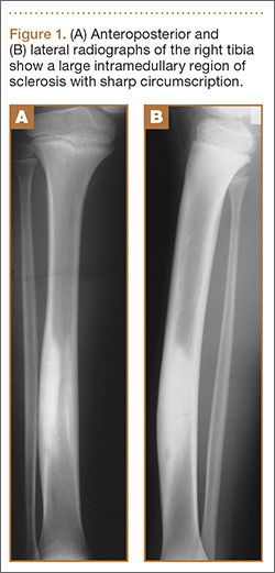
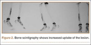
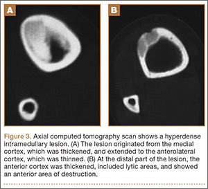
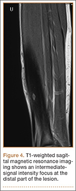
A 10-year-old boy was admitted for surgical repair of an inguinal hernia. Physical examination revealed a painless but tender anterior bowing of the right tibial diaphysis. The patient was a healthy-appearing white male with normal vital signs, gait, and posture. His parents noticed a slight protuberance of the tibia at age 2.5 years. No medical advice was asked for the bone swelling after that time. After recovery from the inguinal hernia repair 3 weeks later, the bone lesion was thoroughly examined. Radiographs showed an oblong, homogenous region of dense sclerosis in the diaphysis of the right tibia. The lesion had relatively well-defined margins and was located in the medullary cavity. Speculations were not obvious in the periphery of the lesion, which exhibited a sharp circumscription (Figures 1A, 1B). A well-defined lytic area was evident at the distal part of the lesion (Figure 1B). There was no periosteal reaction. Blood and serum chemistries were within normal limits, including serum calcium, phosphorus, and alkaline phosphatase. A conventional 3-phase bone scintigraphy (300 MBq) with technetium-99m HDP (hydroxydiphosphonate) indicated increased uptake in the area of the lesion but no other skeletal abnormality (Figure 2). Computed tomography (CT) showed that the lesion was purely intramedullary and densely blastic. The lesion originated from the medial cortex, which was thickened (Figure 3A). The lesion extended to the anterolateral cortex, which was thinned and included a lytic area. In the distal part of the lesion, the anterolateral cortex was thickened, included lytic areas, and exhibited an anterior portion of cortical destruction (Figure 3B). The fatty marrow adjacent to the region of sclerosis appeared normal. There was no evidence of extraosseous soft-tissue changes. On both T1- and T2-weighted magnetic resonance imaging (MRI), the lesion exhibited low-signal intensity. The lesion measured 10.8×2.2×1 cm. It originated from the medial cortical bone of the tibia, blended into the medullary cavity, and extended anteriorly towards and through the anterior cortex. The area of cortical destruction was clearly evident on the axial MRI. The periosteum was displaced and eroded anteriorly by focal radiating bony streaks. No enhancement was seen after the intravenous administration of gadolinium-diethylenetriamine pentaacetic acid (Gd-DTPA) as a contrast medium. There were no extraosseous soft-tissue changes. In the distal part of the lesion, sagittal and axial MRI showed a 1.2×0.8×0.7-cm well-defined ovoid focus, with characteristics of cystic degeneration that exhibited intermediate-signal intensity on T1-weighted MRI (Figure 4) and high-signal intensity on T2-weighted MRI.
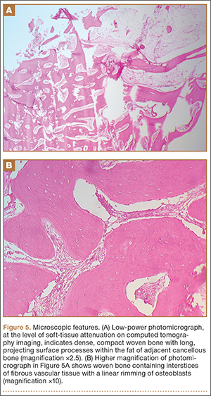
An open biopsy was performed. Macroscopically, a wedge of compact bone measuring 3×1.7×0.6 cm was taken. Microscopic examination showed a thinned periphery of lamellar (mature) bone with haversian canals and, beneath it, woven (immature) bone with long-surface processes projecting within adjacent cancellous bone (Figure 5A). The woven bone contained loose vascular fibrous tissue. No osteoclasts were noted, and the very few osteoblasts lining the bone trabeculae were small, single-layered, and flat (Figure 5B). There was no evidence of neoplastic cells. There was no abnormality of the periosteum and the surrounding soft tissues.
The histology was pathognomonic of a giant bone island. No additional surgical intervention was recommended.
The postoperative course was uncomplicated, and the patient was discharged 2 weeks later. An above-the-knee plaster was recommended for 3 months and a below-the-knee splint for an additional 2-month period. Full weight-bearing was allowed only after the postsurgical sixth month to prevent an impending fracture. The tibial bowing was tender to pressure or palpation, and the patient reported mild spontaneous pain during follow-up. Radiographs 1 year after surgery indicated that the bone area removed for biopsy was replaced by compact bone. MRI performed 4 years after surgery showed that the volume of the lesion in relation to the host bone was not changed.
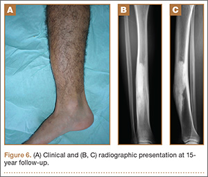
At the last follow-up 15 years after surgery, the anterior tibial bowing was not changed (Figure 6A), but the patient additionally complained of skin irritation after intense training wearing boots during military service. The radiographic appearance of the lesion was also not changed, while the periphery of the lesion exhibited scarce radiating bony streaks with rounded contours (Figures 6B, 6C). The clinical symptoms and signs from wearing military boots completely subsided after a couple of weeks’ rest from daily army activities, but the mild spontaneous pain and the local tenderness over the tibial bowing persisted.
Discussion
Giant bone islands are more likely to be associated with clinical symptoms than the usual small-sized bone island. Some degree of pain was detected in 8 of 10 patients with a giant bone island presented in the literature, but it was induced by trauma in 3 of them.14
Radiographic appearance is among the distinguishing diagnostic features of a giant bone island. It appears as an ovoid, round, or oblong, homogenously dense, single or multiple focus of sclerosis within the medullary cavity; it is oriented along the long axis of the host bone, and it exhibits peripheral pseudopodia or radiating spicules producing the typical “thorny” or “paintbrush” appearance.8,16,17 It does not exhibit cortical penetration and it is not associated with periosteal reaction.10
The CT findings include a sclerotic and hyperdense focus with spiculated margins extending into the adjacent cancellous bone. The lack of bone destruction and soft-tissue mass are also diagnostic.3,7 MRI findings will reflect the low-signal intensity characteristics of cortical bone on all pulse sequences.18
Enostoses usually exhibit no activity on skeletal scintigraphy, while giant lesions generally show increased radiotracer uptake.5,9-11,14,19-27 The latter may result from the increased amount of bone turnover, which is seen more often with larger lesions because of active bone deposition and remodeling.20,21,23,28 Histopathology of a giant bone island appears identical to the well-described pathologic appearance of smaller bone islands. The lesion is composed of compact lamellar bone and haversian systems, which blend with the adjacent spongiosa. The surrounding cancellous bone forms thorn-like trabeculae radiating from the lesion and merging with the cancellous bone.1,4,5,8,28
The presumptive diagnosis of a bone island is based on the clinical findings, imaging features, and follow-up examinations. An asymptomatic, isolated, sclerotic bone lesion showing the typical features of a bone island on plain radiography, CT, and MRI, whatever its size, that is nonactive on bone scan may be easily diagnosed. However, a symptomatic patient with a hot lesion on scintigraphy should be carefully observed. In addition, larger lesions may raise the suspicion of a neoplasm, such as a sclerotic variant of osteosarcoma. In such cases, an open biopsy may be undertaken. No specific treatment is required after the diagnosis has been confirmed. There is no literature to suggest that, after adequate biopsy confirmation, excision or resection is necessary. Follow-up radiographic examination of the lesion should be suggested to monitor for any potential growth.2,10,23
The first giant bone island appearing in a child is presented in this report. The lack of a causative factor leading to the anterior tibial bowing indicated that the bone deformity was caused primarily by the lesion. The present case is unusual for the appearance of several atypical features, some of which have not been previously described. Peripheral radiating spiculated margin was absent on the patient’s initial radiographs and CT imaging. MRI indicated only the presence of radiating bony streaks that displaced and eroded the periosteum on the anterior border of the lesion. The CT findings that the lesion likely originated or was in close proximity with the medial cortex of the tibia were also atypical. It has been previously reported that spinal lesions located immediately below the cortex tend to fuse with the endosteal surface, while similar features may also be seen in the appendicular enostoses.4,29 Other CT findings, such as the thinning of the overlying anterolateral cortical bone, as well as the cortical thickening at the periphery of the lesion associated with areas of soft-tissue attenuation and anterior cortical destruction, have not been described even in the atypical features of a giant bone island. The lytic area resembling a nidus that was evident at the distal part of the lesion was more likely consistent with an area of resorption, which, although rare, has been described on giant lesions.2,9,29 The substantial amount of woven bone transforming to lamellar bone that was evident in the present patient’s microscopic features is also an atypical finding, although it may be expected to some degree in scintigraphically hot, large lesions.28 The clinical and imaging progress of the lesion supported the diagnosis of a giant bone island. The degree of the anterior tibial bowing and the volume of the lesion in relation to the host bone were not changed throughout the follow-up period, indicating that the growth of the lesion followed the growth of the normal bone.
The differential diagnosis of a giant bone island includes a variety of benign tumors and tumor-like lesions, as well as malignant bone lesions.2,4,23,28,30,31 In the patient presented in this report, the diagnosis of an atypical sclerotic presentation of a nonossifying fibroma or healing stage of this lesion could be consistent with some of the CT findings, including the eccentric origin from the cortex associated with medial cortical thickening, the anterolateral cortical thinning, and the soft-tissue attenuation of cortical areas. In addition, unifocal osteofibrous dysplasia may also present with a long intracortical diaphyseal lucency within an area of marked cortical sclerosis and cause a bowing deformity. Both diagnoses were excluded, since no fibrous stroma was evident on the histologic examination of the lesion. A large or giant long-bone osteoma would be associated with the outer cortical margin of bone but would not involve the intramedullary space. The scintigraphically increased uptake of radioisotope, as well as the CT and MRI findings, were not consistent with the diagnosis of osteoid osteoma, osteoblastoma, or osteomyelitis. Although most imaging findings were consistent with a benign lesion, and contrast-enhanced MRI showed no increased vascularity, anterior cortical disruption necessitated a bone biopsy to rule out any potential malignancy.
The histopathology in association with the clinical and imaging findings indicated the diagnosis of a giant bone island. The increased proportion of maturing woven bone over lamellar bone indicated an active remodeling lesion that could be related to the patient’s age, since the clinical and radiographic features of the lesion were not changed after 15-year follow-up.
Conclusion
This is the first giant bone island diagnosed in a patient before puberty. Its greatest length was 10.8 cm, which is the longest reported in the literature. The imaging appearance included several atypical features that are very rare or have not been reported. Microscopic features indicated less mature lamellar bone and a prominent proportion of maturing woven bone. The clinical and the radiographic appearance of the lesion were not changed after 15-year follow-up.
1. Smith J. Giant bone islands. Radiology. 1973;7(1):35-36.
2. Mirra JM. Bone Tumors: Clinical, Radiologic and Pathologic Correlations. Philadelphia, PA: Lea & Febiger; 1989.
3. Greenspan A. Bone island (enostosis): current concept - a review. Skeletal Radiol. 1995;24(2):111-115.
4. Kransdorf MJ, Peterson JJ, Bancroft LW. MR imaging of the knee: incidental osseous lesions. Radiol Clin North Am. 2007;45(6):943-954.
5. Gold RH, Mirra JM, Remotti F, Pignatti G. Case report 527: Giant bone island of tibia. Skeletal Radiol. 1989;18(2):129-132.
6. Onitsuka H. Roentgenologic aspects of bone islands. Radiology. 1977;123(3):607-612.
7. Ehara S, Kattapuram SV, Rosenberg AE. Giant bone island. Computed tomography findings. Clin Imaging. 1989;13(3):231-233.
8. Greenspan A, Steiner G, Knutzon R. Bone island (enostosis): clinical significance and radiologic and pathologic correlations. Skeletal Radiol. 1991;20(2):85-90.
9. Avery GR, Wilsdon JB, Malcolm AJ. Giant bone island with some central resorption. Skeletal Radiol. 1995;24(1):59-60.
10. Brien EW, Mirra JM, Latanza L, Fedenko A, Luck J Jr. Giant bone island of femur. Case report, literature review, and its distinction from low grade osteosarcoma. Skeletal Radiol. 1995;24(7):546-550.
11. Greenspan A, Klein MJ. Giant bone island. Skeletal Radiol. 1996;25(1):67-69.
12. Trombetti A, Noël E. Giant bone islands: a case with 31 years of follow-up. Joint Bone Spine. 2002;69(1):81-84.
13. Dhaon BK, Gautam VK, Jain P, Jaiswal A, Nigam V. Giant bone island of femur complicating replacement arthroplasty: a report of two cases. J Surg Orthop Adv. 2004;13(4):220-223.
14. Park HS, Kim JR, Lee SY, Jang KY. Symptomatic giant (10-cm) bone island of the tibia. Skeletal Radiol. 2005;34(6):347-350.
15. Ikeuchi M, Komatsu M, Tani T. Giant bone island of femur with femoral head necrosis: a case report. Arch Orthop Trauma Surg. 2010;130(4):447-450.
16. Kim SK, Barry WF Jr. Bone island. Am J Roentgenol Radium Ther Nucl Med. 1964;92:1301-1306.
17. Kim SK, Barry WF Jr. Bone islands. Radiology. 1968;90(1):77-78.
18. Cerase A, Priolo F. Skeletal benign bone-forming lesions. Eur J Radiol. 1998;27:S91–S97.
19. Go RT, El-Khoury GY, Wehbe MA. Radionuclide bone image in growing and stable bone island. Skeletal Radiol. 1980;5(1):15-18.
20. Hall FM, Goldberg RP, Davies JA, Fainsinger MH. Scintigraphic assessment of bone islands. Radiology. 1980;135(3):737-742.
21. Greenspan A, Stadalnik RC. Bone island: scintigraphic findings and their clinical application. Can Assoc Radiol J. 1995;46(5):368-379.
22. Sickles EA, Genant HK, Hoffer PB. Increased localization of 99mTc-pyrophosphate in a bone island: case report. J Nucl Med. 1976;17(2):113-115.
23. Dorfman HD, Czerniak B. Bone Tumors. St Louis: Mosby; 1998.
24. Ngan H. Growing bone islands. Clin Radiol. 1972;23(2):199-201.
25. Davies JA, Hall FM, Goldberg RP, Kasdon EJ. Positive bone scan in a bone island. Case report. J Bone Joint Surg Am. 1979;61(6):943-945.
26. Simon K, Mulligan ME. Growing bone islands revisited. A case report. J Bone Joint Surg Am. 1985;67(5):809-811.
27. Blank N, Lieber A. The significance of growing bone islands. Radiology. 1965;85(3):508-511.
28. Greenspan A, Gernot J, Wolfgang R. Differential Diagnosis of Orthopaedic Oncology. Philadelphia, PA: Lippincott Williams & Wilkins; 2007.
29. Kransdorf MJ, Murphey MD. Osseous tumors. In: Davies AM, Sundaram M, James SLJ, eds. Imaging of Bone Tumors and Tumor-Like Lesions. Berlin, Germany: Springer-Verlag; 2009.
30. Mödder B, Guhl B, Schaefer HE. Growing bone islands as differential diagnosis of osteoplastic metastases. Rontgenblatter. 1980;33(6):286-288.
31. Flechner RE, Mills SE. Atlas of Tumor Pathology: Tumors of the Bones and Joints. Washington, DC: Armed Forces Institute of Pathology; 1993.
A bone island is a focus of normal cortical bone located within the medullary cavity. The vast majority of bone islands are small, measuring from 1 mm to 2 cm in size. They are found more frequently in adults than in children. The lesion can be virtually diagnosed on the basis of its characteristic clinical and imaging features. Differential diagnosis may be difficult when the lesion manifests itself uncharacteristically by being symptomatic, very large, and hot on bone scan.1-4
The term giant bone island has been used to describe a large lesion1 that measures more than 2 cm in any dimension.5 Giant bone islands have been described only in adults,1,5-15 and the longest bone island length reported is 10.5 cm.10 They are usually symptomatic and associated with increased radionuclide uptake on bone scintigraphy.14
The history and the clinical and imaging presentation of an even longer, symptomatic, and scintigraphically hot lesion in the tibial diaphysis of a 10-year-old boy is reported. The lesion further exhibited several atypical imaging features necessitating an open biopsy, which confirmed the diagnosis of a giant bone island. The pertinent differential diagnosis and the clinical and radiographic findings after 15-year follow-up are also presented and discussed. The patient provided written informed consent for print and electronic publication of this case report.
Case Report
A 10-year-old boy was admitted for surgical repair of an inguinal hernia. Physical examination revealed a painless but tender anterior bowing of the right tibial diaphysis. The patient was a healthy-appearing white male with normal vital signs, gait, and posture. His parents noticed a slight protuberance of the tibia at age 2.5 years. No medical advice was asked for the bone swelling after that time. After recovery from the inguinal hernia repair 3 weeks later, the bone lesion was thoroughly examined. Radiographs showed an oblong, homogenous region of dense sclerosis in the diaphysis of the right tibia. The lesion had relatively well-defined margins and was located in the medullary cavity. Speculations were not obvious in the periphery of the lesion, which exhibited a sharp circumscription (Figures 1A, 1B). A well-defined lytic area was evident at the distal part of the lesion (Figure 1B). There was no periosteal reaction. Blood and serum chemistries were within normal limits, including serum calcium, phosphorus, and alkaline phosphatase. A conventional 3-phase bone scintigraphy (300 MBq) with technetium-99m HDP (hydroxydiphosphonate) indicated increased uptake in the area of the lesion but no other skeletal abnormality (Figure 2). Computed tomography (CT) showed that the lesion was purely intramedullary and densely blastic. The lesion originated from the medial cortex, which was thickened (Figure 3A). The lesion extended to the anterolateral cortex, which was thinned and included a lytic area. In the distal part of the lesion, the anterolateral cortex was thickened, included lytic areas, and exhibited an anterior portion of cortical destruction (Figure 3B). The fatty marrow adjacent to the region of sclerosis appeared normal. There was no evidence of extraosseous soft-tissue changes. On both T1- and T2-weighted magnetic resonance imaging (MRI), the lesion exhibited low-signal intensity. The lesion measured 10.8×2.2×1 cm. It originated from the medial cortical bone of the tibia, blended into the medullary cavity, and extended anteriorly towards and through the anterior cortex. The area of cortical destruction was clearly evident on the axial MRI. The periosteum was displaced and eroded anteriorly by focal radiating bony streaks. No enhancement was seen after the intravenous administration of gadolinium-diethylenetriamine pentaacetic acid (Gd-DTPA) as a contrast medium. There were no extraosseous soft-tissue changes. In the distal part of the lesion, sagittal and axial MRI showed a 1.2×0.8×0.7-cm well-defined ovoid focus, with characteristics of cystic degeneration that exhibited intermediate-signal intensity on T1-weighted MRI (Figure 4) and high-signal intensity on T2-weighted MRI.
An open biopsy was performed. Macroscopically, a wedge of compact bone measuring 3×1.7×0.6 cm was taken. Microscopic examination showed a thinned periphery of lamellar (mature) bone with haversian canals and, beneath it, woven (immature) bone with long-surface processes projecting within adjacent cancellous bone (Figure 5A). The woven bone contained loose vascular fibrous tissue. No osteoclasts were noted, and the very few osteoblasts lining the bone trabeculae were small, single-layered, and flat (Figure 5B). There was no evidence of neoplastic cells. There was no abnormality of the periosteum and the surrounding soft tissues.
The histology was pathognomonic of a giant bone island. No additional surgical intervention was recommended.
The postoperative course was uncomplicated, and the patient was discharged 2 weeks later. An above-the-knee plaster was recommended for 3 months and a below-the-knee splint for an additional 2-month period. Full weight-bearing was allowed only after the postsurgical sixth month to prevent an impending fracture. The tibial bowing was tender to pressure or palpation, and the patient reported mild spontaneous pain during follow-up. Radiographs 1 year after surgery indicated that the bone area removed for biopsy was replaced by compact bone. MRI performed 4 years after surgery showed that the volume of the lesion in relation to the host bone was not changed.
At the last follow-up 15 years after surgery, the anterior tibial bowing was not changed (Figure 6A), but the patient additionally complained of skin irritation after intense training wearing boots during military service. The radiographic appearance of the lesion was also not changed, while the periphery of the lesion exhibited scarce radiating bony streaks with rounded contours (Figures 6B, 6C). The clinical symptoms and signs from wearing military boots completely subsided after a couple of weeks’ rest from daily army activities, but the mild spontaneous pain and the local tenderness over the tibial bowing persisted.
Discussion
Giant bone islands are more likely to be associated with clinical symptoms than the usual small-sized bone island. Some degree of pain was detected in 8 of 10 patients with a giant bone island presented in the literature, but it was induced by trauma in 3 of them.14
Radiographic appearance is among the distinguishing diagnostic features of a giant bone island. It appears as an ovoid, round, or oblong, homogenously dense, single or multiple focus of sclerosis within the medullary cavity; it is oriented along the long axis of the host bone, and it exhibits peripheral pseudopodia or radiating spicules producing the typical “thorny” or “paintbrush” appearance.8,16,17 It does not exhibit cortical penetration and it is not associated with periosteal reaction.10
The CT findings include a sclerotic and hyperdense focus with spiculated margins extending into the adjacent cancellous bone. The lack of bone destruction and soft-tissue mass are also diagnostic.3,7 MRI findings will reflect the low-signal intensity characteristics of cortical bone on all pulse sequences.18
Enostoses usually exhibit no activity on skeletal scintigraphy, while giant lesions generally show increased radiotracer uptake.5,9-11,14,19-27 The latter may result from the increased amount of bone turnover, which is seen more often with larger lesions because of active bone deposition and remodeling.20,21,23,28 Histopathology of a giant bone island appears identical to the well-described pathologic appearance of smaller bone islands. The lesion is composed of compact lamellar bone and haversian systems, which blend with the adjacent spongiosa. The surrounding cancellous bone forms thorn-like trabeculae radiating from the lesion and merging with the cancellous bone.1,4,5,8,28
The presumptive diagnosis of a bone island is based on the clinical findings, imaging features, and follow-up examinations. An asymptomatic, isolated, sclerotic bone lesion showing the typical features of a bone island on plain radiography, CT, and MRI, whatever its size, that is nonactive on bone scan may be easily diagnosed. However, a symptomatic patient with a hot lesion on scintigraphy should be carefully observed. In addition, larger lesions may raise the suspicion of a neoplasm, such as a sclerotic variant of osteosarcoma. In such cases, an open biopsy may be undertaken. No specific treatment is required after the diagnosis has been confirmed. There is no literature to suggest that, after adequate biopsy confirmation, excision or resection is necessary. Follow-up radiographic examination of the lesion should be suggested to monitor for any potential growth.2,10,23
The first giant bone island appearing in a child is presented in this report. The lack of a causative factor leading to the anterior tibial bowing indicated that the bone deformity was caused primarily by the lesion. The present case is unusual for the appearance of several atypical features, some of which have not been previously described. Peripheral radiating spiculated margin was absent on the patient’s initial radiographs and CT imaging. MRI indicated only the presence of radiating bony streaks that displaced and eroded the periosteum on the anterior border of the lesion. The CT findings that the lesion likely originated or was in close proximity with the medial cortex of the tibia were also atypical. It has been previously reported that spinal lesions located immediately below the cortex tend to fuse with the endosteal surface, while similar features may also be seen in the appendicular enostoses.4,29 Other CT findings, such as the thinning of the overlying anterolateral cortical bone, as well as the cortical thickening at the periphery of the lesion associated with areas of soft-tissue attenuation and anterior cortical destruction, have not been described even in the atypical features of a giant bone island. The lytic area resembling a nidus that was evident at the distal part of the lesion was more likely consistent with an area of resorption, which, although rare, has been described on giant lesions.2,9,29 The substantial amount of woven bone transforming to lamellar bone that was evident in the present patient’s microscopic features is also an atypical finding, although it may be expected to some degree in scintigraphically hot, large lesions.28 The clinical and imaging progress of the lesion supported the diagnosis of a giant bone island. The degree of the anterior tibial bowing and the volume of the lesion in relation to the host bone were not changed throughout the follow-up period, indicating that the growth of the lesion followed the growth of the normal bone.
The differential diagnosis of a giant bone island includes a variety of benign tumors and tumor-like lesions, as well as malignant bone lesions.2,4,23,28,30,31 In the patient presented in this report, the diagnosis of an atypical sclerotic presentation of a nonossifying fibroma or healing stage of this lesion could be consistent with some of the CT findings, including the eccentric origin from the cortex associated with medial cortical thickening, the anterolateral cortical thinning, and the soft-tissue attenuation of cortical areas. In addition, unifocal osteofibrous dysplasia may also present with a long intracortical diaphyseal lucency within an area of marked cortical sclerosis and cause a bowing deformity. Both diagnoses were excluded, since no fibrous stroma was evident on the histologic examination of the lesion. A large or giant long-bone osteoma would be associated with the outer cortical margin of bone but would not involve the intramedullary space. The scintigraphically increased uptake of radioisotope, as well as the CT and MRI findings, were not consistent with the diagnosis of osteoid osteoma, osteoblastoma, or osteomyelitis. Although most imaging findings were consistent with a benign lesion, and contrast-enhanced MRI showed no increased vascularity, anterior cortical disruption necessitated a bone biopsy to rule out any potential malignancy.
The histopathology in association with the clinical and imaging findings indicated the diagnosis of a giant bone island. The increased proportion of maturing woven bone over lamellar bone indicated an active remodeling lesion that could be related to the patient’s age, since the clinical and radiographic features of the lesion were not changed after 15-year follow-up.
Conclusion
This is the first giant bone island diagnosed in a patient before puberty. Its greatest length was 10.8 cm, which is the longest reported in the literature. The imaging appearance included several atypical features that are very rare or have not been reported. Microscopic features indicated less mature lamellar bone and a prominent proportion of maturing woven bone. The clinical and the radiographic appearance of the lesion were not changed after 15-year follow-up.
1. Smith J. Giant bone islands. Radiology. 1973;7(1):35-36.
2. Mirra JM. Bone Tumors: Clinical, Radiologic and Pathologic Correlations. Philadelphia, PA: Lea & Febiger; 1989.
3. Greenspan A. Bone island (enostosis): current concept - a review. Skeletal Radiol. 1995;24(2):111-115.
4. Kransdorf MJ, Peterson JJ, Bancroft LW. MR imaging of the knee: incidental osseous lesions. Radiol Clin North Am. 2007;45(6):943-954.
5. Gold RH, Mirra JM, Remotti F, Pignatti G. Case report 527: Giant bone island of tibia. Skeletal Radiol. 1989;18(2):129-132.
6. Onitsuka H. Roentgenologic aspects of bone islands. Radiology. 1977;123(3):607-612.
7. Ehara S, Kattapuram SV, Rosenberg AE. Giant bone island. Computed tomography findings. Clin Imaging. 1989;13(3):231-233.
8. Greenspan A, Steiner G, Knutzon R. Bone island (enostosis): clinical significance and radiologic and pathologic correlations. Skeletal Radiol. 1991;20(2):85-90.
9. Avery GR, Wilsdon JB, Malcolm AJ. Giant bone island with some central resorption. Skeletal Radiol. 1995;24(1):59-60.
10. Brien EW, Mirra JM, Latanza L, Fedenko A, Luck J Jr. Giant bone island of femur. Case report, literature review, and its distinction from low grade osteosarcoma. Skeletal Radiol. 1995;24(7):546-550.
11. Greenspan A, Klein MJ. Giant bone island. Skeletal Radiol. 1996;25(1):67-69.
12. Trombetti A, Noël E. Giant bone islands: a case with 31 years of follow-up. Joint Bone Spine. 2002;69(1):81-84.
13. Dhaon BK, Gautam VK, Jain P, Jaiswal A, Nigam V. Giant bone island of femur complicating replacement arthroplasty: a report of two cases. J Surg Orthop Adv. 2004;13(4):220-223.
14. Park HS, Kim JR, Lee SY, Jang KY. Symptomatic giant (10-cm) bone island of the tibia. Skeletal Radiol. 2005;34(6):347-350.
15. Ikeuchi M, Komatsu M, Tani T. Giant bone island of femur with femoral head necrosis: a case report. Arch Orthop Trauma Surg. 2010;130(4):447-450.
16. Kim SK, Barry WF Jr. Bone island. Am J Roentgenol Radium Ther Nucl Med. 1964;92:1301-1306.
17. Kim SK, Barry WF Jr. Bone islands. Radiology. 1968;90(1):77-78.
18. Cerase A, Priolo F. Skeletal benign bone-forming lesions. Eur J Radiol. 1998;27:S91–S97.
19. Go RT, El-Khoury GY, Wehbe MA. Radionuclide bone image in growing and stable bone island. Skeletal Radiol. 1980;5(1):15-18.
20. Hall FM, Goldberg RP, Davies JA, Fainsinger MH. Scintigraphic assessment of bone islands. Radiology. 1980;135(3):737-742.
21. Greenspan A, Stadalnik RC. Bone island: scintigraphic findings and their clinical application. Can Assoc Radiol J. 1995;46(5):368-379.
22. Sickles EA, Genant HK, Hoffer PB. Increased localization of 99mTc-pyrophosphate in a bone island: case report. J Nucl Med. 1976;17(2):113-115.
23. Dorfman HD, Czerniak B. Bone Tumors. St Louis: Mosby; 1998.
24. Ngan H. Growing bone islands. Clin Radiol. 1972;23(2):199-201.
25. Davies JA, Hall FM, Goldberg RP, Kasdon EJ. Positive bone scan in a bone island. Case report. J Bone Joint Surg Am. 1979;61(6):943-945.
26. Simon K, Mulligan ME. Growing bone islands revisited. A case report. J Bone Joint Surg Am. 1985;67(5):809-811.
27. Blank N, Lieber A. The significance of growing bone islands. Radiology. 1965;85(3):508-511.
28. Greenspan A, Gernot J, Wolfgang R. Differential Diagnosis of Orthopaedic Oncology. Philadelphia, PA: Lippincott Williams & Wilkins; 2007.
29. Kransdorf MJ, Murphey MD. Osseous tumors. In: Davies AM, Sundaram M, James SLJ, eds. Imaging of Bone Tumors and Tumor-Like Lesions. Berlin, Germany: Springer-Verlag; 2009.
30. Mödder B, Guhl B, Schaefer HE. Growing bone islands as differential diagnosis of osteoplastic metastases. Rontgenblatter. 1980;33(6):286-288.
31. Flechner RE, Mills SE. Atlas of Tumor Pathology: Tumors of the Bones and Joints. Washington, DC: Armed Forces Institute of Pathology; 1993.
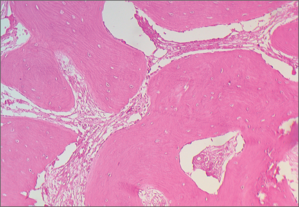
Nonconsecutive Pars Interarticularis Defects
Spondylolysis is a bone defect of the pars interarticularis. It is usually seen in adolescents who participate in sporting activities that involve repetitive axial loads to a hyperextended lower back, such as football offensive lineman, throwing athletes, and gymnasts. It occurs frequently in the L5 pars and can be unilateral or bilateral. The majority of reported multiple-level spondylolysis is at consecutive lumbar segments.1-6 Rarely, it affects noncontiguous levels. Most patients respond well to conservative treatment in the form of activity modification and orthosis.7 Surgical intervention is considered if 6 months of conservative management fails, spondylolisthesis develops, or intractable neurologic symptoms arise.
This case report presents an 18-year-old man with noncontiguous spondylolysis at L2 and L5 who was successfully treated with a 1-level pars repair at L2 after failed conservative management. This unique case highlights the importance of using single-photon emission computed tomography (SPECT) scan and diagnostic pars block when planning for surgical treatment in the rare cases of noncontiguous spondylolysis. The patient provided written informed consent for print and electronic publication of this case report.
Case Report
An 18-year-old man presented to the clinic with worsening lower back pain for the previous 4 weeks. He was playing high school baseball and stated the pain was worse when he swung his bat. He had no history of trauma or back pain. Rest was the only alleviating factor, and he was beginning to experience pain when he stood after sitting. He denied any radicular pain. On examination, he had midline tenderness along the upper lumbar spine and pain with lumbar spine extension. His neurologic examination showed normal sensation with 5/5 strength in all key muscle groups. Plain radiograph of the lumbar spine showed an L5 pars defect (Figures 1A, 1B). A SPECT scan showed increased uptake at L2 pars bilaterally; the L5 pars did not show increased uptake (Figures 2A, 2B). A computed tomography (CT) scan confirmed bilateral L2 pars fractures and a left L5 pars fracture (Figures 3A, 3B). Bony changes in the form of marginal sclerosis at the L5, but not the L2, pars suggested that the L2 fracture was acute while the L5 fracture was chronic (Figures 4A, 4B).
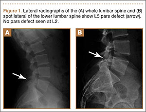

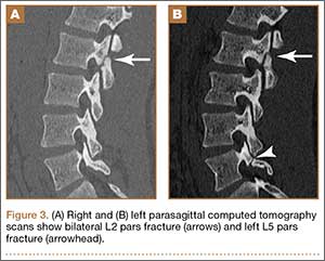

The patient had conservative management for 6 months in the form of lumbosacral orthosis (LSO), cessation of sports activities, and physical therapy. The patient was initially treated with an LSO brace for 3 months, after which he had physical therapy. At 6 month follow-up, he reported continuing, significant back pain. A repeat CT scan of the lumbar spine showed no interval healing of the bilateral L2 or the unilateral L5 pars fractures. As a result of the patient’s noncontiguous pars fractures, a diagnostic CT-guided block of L2 pars was performed to identify which level was his main pain generator (Figure 5). He reported a brief period of complete pain relief after the L2 pars block. With failure of 6 months’ conservative management and positive SPECT scan and diagnostic block, surgical treatment was recommended. Prior to surgical intervention, magnetic resonance imaging was obtained to rule out pathology (eg, disc degeneration, infection, or tumor) other than the pars defect that could require fusion instead of pars repair (Figures 6A, 6B). Because of the patient’s young age, bilateral L2 pars repair rather than fusion was indicated. After 8 months of persistent back pain, he underwent bilateral L2 pars repair with iliac crest autograft, pedicle screws, and sublaminar hook fixation (Figures 7A, 7B). The patient had an uneventful immediate postoperative course. A 6-month postoperative CT scan showed bridging callus at the L2 pars; however, the left L5 pars fracture was still visible (Figures 8A-8C). Over a 6-month postoperative period, the patient had continued improvement in his back pain, advanced his activity as tolerated without problem, and was allowed to resume his sports activities. At 2-year follow-up, he was playing baseball and basketball, and denied any back pain.


Discussion
Lumbar spondylolysis is commonly seen at the fourth and fifth lumbar vertebrae, and accounts for more than 95% of spondylolysis cases.8 Multiple-level spondylolysis is a relatively rare finding with an incidence varying between 1.2% and 5.6%. The majority of the reported multiple-level cases are adjacent.1-3,6 Adolescents often present with a history of insidious-onset low back pain without radicular symptoms that is exacerbated by activity. Occasionally, an acute injury may elicit the onset of pain. A thorough history with emphasis on pain in relation to activity and sports involvement is beneficial. The patient in the current study was a throwing athlete and presented with 4 weeks of back pain that worsened with activity; he had no history of trauma.
Radiographic assessment using standing anteroposterior, lateral, and oblique radiographs of the thoracolumbar spine is useful in the initial assessment. A SPECT scan of the lumbosacral spine is highly sensitive for identifying spondylolytic defects when plain radiographs are within normal limits, yet a high index of suspicion remains given the patient’s history and physical examination findings.9,10 Increased radionuclide uptake within the pars indicates a stress reaction and, possibly, a more acute pathology. The plain radiographs of the patient showed only L5 spondylolysis. However, a SPECT scan showed only increased uptake in L2 pars on both sides. These findings suggested chronic L5 and acute L2 pars defects. A thin-cut CT scan gives the best visualization of pars defect and can help in differentiating chronic defect with sclerotic margins versus acute defect with hazy irregular margins. In the current case, the CT scan showed changes consistent with unilateral chronic L5 and bilateral acute L2 pars defects.
The origin of the pain in spondylolysis is from the tissues rich in nociceptive nerve endings in the loose posterior arch. A CT-guided pars block is a very useful diagnostic preoperative tool that confirms the symptomatic level in cases of multilevel pars defect, especially if they are noncontiguous. In this case, the diagnostic preoperative bilateral L2 pars block confirmed that the pain generator was the acute L2 rather than the chronic L5 pars defect. This step assured that surgical treatment involving only the L2 level would be beneficial in alleviating the patient’s back pain after the failure of 6 months of conservative treatment.
Most patients with single-level spondylolysis respond to conservative treatment, especially after early diagnosis and treatment. The traditional nonoperative treatment of children and adolescents with a symptomatic spondylolytic lesion was a period of rest and progressive increased activity with physical therapy. Immobilization with an LSO was reserved for individuals who did not respond to rest and physical therapy.11 However, multiple studies revealed early immobilization achieved results superior to activity restriction alone, and individuals who underwent a period of activity restriction prior to bracing were more likely to experience persistent symptoms.12-14 Our patient underwent conservative treatment for 6 months, in the form of LSO, cessation of sport activities, and physical therapy, which failed to give him relief of his back pain.
Surgical intervention is warranted for adolescents with persistent, debilitating pain intractable to at least a 6-month period of nonoperative management. Additional indications for surgical management are those individuals who present with neurologic deficits and isthmic spondylolisthesis. Surgical treatment involves direct pars repair with iliac crest bone graft and use of a sublaminar hook/pedicle screw construct, cerclage wire, or pars screw.15-18
In contrast to single-level pars defects that respond well to conservative treatment, there are conflicting reports regarding the management of multiple-level pars fractures; a few reports suggest good outcome with conservative management, but the majority state that surgery is often required and conservative measures are rarely useful.1-4,6 Nayeemuddin and colleagues19 reported a case of a 16-year-old football player who presented with a 4-month history of constant low back pain related to bilateral L3 and L5 pars defects that responded to 1 year of conservative management, when the more acute fractures at L3 showed complete bony union and the patient had symptomatic pain relief and was able to return to full sporting activity.
Chang and colleagues2 reported 10 patients with adjacent 2-level bilateral spondylolysis treated successfully using a pedicle screw–hook construct with autogenous bone grafting. Ogawa and colleagues5 reported adjacent 2-level spondylolysis in 5 patients and 3-level spondylolysis in 2 patients, who were treated successfully by segmental wire fixation and bone grafting. Ivanic and colleagues15 retrospectively reviewed 113 patients with spondylolysis who were treated with direct repair using a hook-screw construct and showed a pseudoarthrosis rate of 13.3%. Superior fusion rates were observed in patients 14 years and younger compared with older patients, particularly those 20 years and older.15 Roca and colleagues16 prospectively analyzed 19 consecutive cases of spondylolysis that were repaired using a hook-screw construct. Twelve of 13 patients (92%) who were 20 years or younger at the time of the study (average age, 17.2 years) had fusion, whereas, in 6 patients 21 years and older (average age, 27.5 years), no cases of fusion were observed. The patients 20 years or younger had significantly better clinical results than those obtained in the patients 21 years and older. The authors concluded that pedicle screw–hook fixation is a useful alternative in the treatment of spondylolysis in adolescents, but did not recommend this procedure in patients older than 20 years.16
Conclusion
The current case demonstrates a unique example of rare noncontiguous pars defects successfully treated with primary repair of 1 level when conservative management failed and the symptomatic defect was isolated. It also highlights the importance of investigating the entirety of the lumbar spine when diagnosis of L5 spondylolysis rules out noncontiguous pars defects. The treatment of noncontiguous pars defects is not well defined; this case showed the importance of using a SPECT scan and a diagnostic pars block to help isolate the symptomatic level when surgical management is considered after a failure of conservative treatment. This case shows 2 possible results: the chronic unilateral L5 defect responded to nonsurgical treatment with asymptomatic fibrous nonunion, while the more acute bilateral L2 defect responded to pars repair with pedicle screw–hook fixation and iliac crest bone graft.
1. Al-Sebai MW, Al-Khawashki H. Spondyloptosis and multiple-level spondylolysis. Eur Spine J. 1999;8(1):75-77.
2. Chang JH, Lee CH, Wu SS, Lin LC, et al. Management of multiple level spondylolysis of the lumbar spine in young males: a report of six cases. J Formos Med Assoc. 2001;100(7)2:497-502.
3. Eingorn D, Pizzutillo PD. Pars interarticularis fusion of multiple levels of lumbar spondylolysis. A case report. Spine. 1985;10(3):250-252.
4. Nozawa S, Shimizu K, Miyamoto K, Tanaka M. Repair of pars interarticularis defect by segmental wire fixation in young athletes with spondylolysis. Am J Sports Med. 2003;31(3):359-364.
5. Ogawa H, Nishimoto H, Hosoe H, Suzuki N, Kanamori Y, Shimizu K. Clinical outcome after segmental wire fixation and bone grafting for repair of the defects in multiple level lumbar spondylolysis. J Spinal Disord Tech. 2007;20(7):521-525.
6. Ravichandran G. Multiple lumbar spondylolyses. Spine. 1980;5(6):552-557.
7. Sys J, Michielsen J, Bracke P, Martens M, Verstreken J. Nonoperative treatment of active spondylolysis in elite athletes with normal X-ray findings: literature review and results of conservative treatment. Eur Spine J. 2001;10(6):498-504.
8. Saraste H. Spondylolysis and spondylolisthesis. Acta Orthop Scand Suppl. 1993;251:84-86.
9. Anderson K, Sarwark JF, Conway JJ, Logue ES, Schafer MS. Quantitative assessment with SPECT imaging of stress injuries of the pars interarticularis and response to bracing. J Pediatr Orthop. 2000;20(1):28-33.
10. Bodner RJ, Heyman S, Drummond DS, Gregg JR. The use of single photon emission computed tomography (SPECT) in the diagnosis of low-back pain in young patients. Spine. 1988;13(10):1155-1160.
11. Steiner ME, Micheli LJ. Treatment of symptomatic spondylolysis and spondylolisthesis with the modified Boston brace. Spine. 1985;10(10):937-943.
12. Blanda J, Bethem D, Moats W, Lew M. Defects of pars interarticularis in athletes: a protocol for nonoperative treatment. J Spinal Disord. 1993;6(5):406-411.
13. Kurd MF, Patel D, Norton R, Picetti G, Friel B, Vaccaro AR. Nonoperative treatment of symptomatic spondylolysis. J Spinal Disord Tech. 2007;20(8):560-564.
14. Pizzutillo PD, Hummer CD 3rd. Nonoperative treatment for painful adolescent spondylolysis or spondylolisthesis. J Pediatr Orthop. 1989;9(5):538-540.
15. Ivanic GM, Pink TP, Achatz W, Ward JC, Homann NC, May M. Direct stabilization of lumbar spondylolysis with a hook screw: mean 11-year follow-up period for 113 patients. Spine. 2003;28(3):255-259.
16. Roca J, Iborra M, Cavanilles-Walker JM, Alberti G. Direct repair of spondylolysis using a new pedicle screw hook fixation: clinical and CT-assessed study: an analysis of 19 patients. J Spinal Disord Tech. 2005;18(suppl):S82-S89.
17. Schlenzka D, Remes V, Helenius I, et al. Direct repair for treatment of symptomatic spondylolysis and low-grade isthmic spondylolisthesis in young patients: no benefit in comparison to segmental fusion after a mean follow-up of 14.8 years. Eur Spine J. 2006;15(10):1437-1447.
18. Buck JE. Direct repair of the defect in spondylolisthesis. Preliminary report. J Bone Joint Surg Br. 1970;52(3):432-437.
19. Nayeemuddin M, Richards PJ, Ahmed EB. The imaging and management of nonconsecutive pars interarticularis defects: a case report and review of literature. Spine J. 2011;11(12):1157-1163.
Spondylolysis is a bone defect of the pars interarticularis. It is usually seen in adolescents who participate in sporting activities that involve repetitive axial loads to a hyperextended lower back, such as football offensive lineman, throwing athletes, and gymnasts. It occurs frequently in the L5 pars and can be unilateral or bilateral. The majority of reported multiple-level spondylolysis is at consecutive lumbar segments.1-6 Rarely, it affects noncontiguous levels. Most patients respond well to conservative treatment in the form of activity modification and orthosis.7 Surgical intervention is considered if 6 months of conservative management fails, spondylolisthesis develops, or intractable neurologic symptoms arise.
This case report presents an 18-year-old man with noncontiguous spondylolysis at L2 and L5 who was successfully treated with a 1-level pars repair at L2 after failed conservative management. This unique case highlights the importance of using single-photon emission computed tomography (SPECT) scan and diagnostic pars block when planning for surgical treatment in the rare cases of noncontiguous spondylolysis. The patient provided written informed consent for print and electronic publication of this case report.
Case Report
An 18-year-old man presented to the clinic with worsening lower back pain for the previous 4 weeks. He was playing high school baseball and stated the pain was worse when he swung his bat. He had no history of trauma or back pain. Rest was the only alleviating factor, and he was beginning to experience pain when he stood after sitting. He denied any radicular pain. On examination, he had midline tenderness along the upper lumbar spine and pain with lumbar spine extension. His neurologic examination showed normal sensation with 5/5 strength in all key muscle groups. Plain radiograph of the lumbar spine showed an L5 pars defect (Figures 1A, 1B). A SPECT scan showed increased uptake at L2 pars bilaterally; the L5 pars did not show increased uptake (Figures 2A, 2B). A computed tomography (CT) scan confirmed bilateral L2 pars fractures and a left L5 pars fracture (Figures 3A, 3B). Bony changes in the form of marginal sclerosis at the L5, but not the L2, pars suggested that the L2 fracture was acute while the L5 fracture was chronic (Figures 4A, 4B).
The patient had conservative management for 6 months in the form of lumbosacral orthosis (LSO), cessation of sports activities, and physical therapy. The patient was initially treated with an LSO brace for 3 months, after which he had physical therapy. At 6 month follow-up, he reported continuing, significant back pain. A repeat CT scan of the lumbar spine showed no interval healing of the bilateral L2 or the unilateral L5 pars fractures. As a result of the patient’s noncontiguous pars fractures, a diagnostic CT-guided block of L2 pars was performed to identify which level was his main pain generator (Figure 5). He reported a brief period of complete pain relief after the L2 pars block. With failure of 6 months’ conservative management and positive SPECT scan and diagnostic block, surgical treatment was recommended. Prior to surgical intervention, magnetic resonance imaging was obtained to rule out pathology (eg, disc degeneration, infection, or tumor) other than the pars defect that could require fusion instead of pars repair (Figures 6A, 6B). Because of the patient’s young age, bilateral L2 pars repair rather than fusion was indicated. After 8 months of persistent back pain, he underwent bilateral L2 pars repair with iliac crest autograft, pedicle screws, and sublaminar hook fixation (Figures 7A, 7B). The patient had an uneventful immediate postoperative course. A 6-month postoperative CT scan showed bridging callus at the L2 pars; however, the left L5 pars fracture was still visible (Figures 8A-8C). Over a 6-month postoperative period, the patient had continued improvement in his back pain, advanced his activity as tolerated without problem, and was allowed to resume his sports activities. At 2-year follow-up, he was playing baseball and basketball, and denied any back pain.
Discussion
Lumbar spondylolysis is commonly seen at the fourth and fifth lumbar vertebrae, and accounts for more than 95% of spondylolysis cases.8 Multiple-level spondylolysis is a relatively rare finding with an incidence varying between 1.2% and 5.6%. The majority of the reported multiple-level cases are adjacent.1-3,6 Adolescents often present with a history of insidious-onset low back pain without radicular symptoms that is exacerbated by activity. Occasionally, an acute injury may elicit the onset of pain. A thorough history with emphasis on pain in relation to activity and sports involvement is beneficial. The patient in the current study was a throwing athlete and presented with 4 weeks of back pain that worsened with activity; he had no history of trauma.
Radiographic assessment using standing anteroposterior, lateral, and oblique radiographs of the thoracolumbar spine is useful in the initial assessment. A SPECT scan of the lumbosacral spine is highly sensitive for identifying spondylolytic defects when plain radiographs are within normal limits, yet a high index of suspicion remains given the patient’s history and physical examination findings.9,10 Increased radionuclide uptake within the pars indicates a stress reaction and, possibly, a more acute pathology. The plain radiographs of the patient showed only L5 spondylolysis. However, a SPECT scan showed only increased uptake in L2 pars on both sides. These findings suggested chronic L5 and acute L2 pars defects. A thin-cut CT scan gives the best visualization of pars defect and can help in differentiating chronic defect with sclerotic margins versus acute defect with hazy irregular margins. In the current case, the CT scan showed changes consistent with unilateral chronic L5 and bilateral acute L2 pars defects.
The origin of the pain in spondylolysis is from the tissues rich in nociceptive nerve endings in the loose posterior arch. A CT-guided pars block is a very useful diagnostic preoperative tool that confirms the symptomatic level in cases of multilevel pars defect, especially if they are noncontiguous. In this case, the diagnostic preoperative bilateral L2 pars block confirmed that the pain generator was the acute L2 rather than the chronic L5 pars defect. This step assured that surgical treatment involving only the L2 level would be beneficial in alleviating the patient’s back pain after the failure of 6 months of conservative treatment.
Most patients with single-level spondylolysis respond to conservative treatment, especially after early diagnosis and treatment. The traditional nonoperative treatment of children and adolescents with a symptomatic spondylolytic lesion was a period of rest and progressive increased activity with physical therapy. Immobilization with an LSO was reserved for individuals who did not respond to rest and physical therapy.11 However, multiple studies revealed early immobilization achieved results superior to activity restriction alone, and individuals who underwent a period of activity restriction prior to bracing were more likely to experience persistent symptoms.12-14 Our patient underwent conservative treatment for 6 months, in the form of LSO, cessation of sport activities, and physical therapy, which failed to give him relief of his back pain.
Surgical intervention is warranted for adolescents with persistent, debilitating pain intractable to at least a 6-month period of nonoperative management. Additional indications for surgical management are those individuals who present with neurologic deficits and isthmic spondylolisthesis. Surgical treatment involves direct pars repair with iliac crest bone graft and use of a sublaminar hook/pedicle screw construct, cerclage wire, or pars screw.15-18
In contrast to single-level pars defects that respond well to conservative treatment, there are conflicting reports regarding the management of multiple-level pars fractures; a few reports suggest good outcome with conservative management, but the majority state that surgery is often required and conservative measures are rarely useful.1-4,6 Nayeemuddin and colleagues19 reported a case of a 16-year-old football player who presented with a 4-month history of constant low back pain related to bilateral L3 and L5 pars defects that responded to 1 year of conservative management, when the more acute fractures at L3 showed complete bony union and the patient had symptomatic pain relief and was able to return to full sporting activity.
Chang and colleagues2 reported 10 patients with adjacent 2-level bilateral spondylolysis treated successfully using a pedicle screw–hook construct with autogenous bone grafting. Ogawa and colleagues5 reported adjacent 2-level spondylolysis in 5 patients and 3-level spondylolysis in 2 patients, who were treated successfully by segmental wire fixation and bone grafting. Ivanic and colleagues15 retrospectively reviewed 113 patients with spondylolysis who were treated with direct repair using a hook-screw construct and showed a pseudoarthrosis rate of 13.3%. Superior fusion rates were observed in patients 14 years and younger compared with older patients, particularly those 20 years and older.15 Roca and colleagues16 prospectively analyzed 19 consecutive cases of spondylolysis that were repaired using a hook-screw construct. Twelve of 13 patients (92%) who were 20 years or younger at the time of the study (average age, 17.2 years) had fusion, whereas, in 6 patients 21 years and older (average age, 27.5 years), no cases of fusion were observed. The patients 20 years or younger had significantly better clinical results than those obtained in the patients 21 years and older. The authors concluded that pedicle screw–hook fixation is a useful alternative in the treatment of spondylolysis in adolescents, but did not recommend this procedure in patients older than 20 years.16
Conclusion
The current case demonstrates a unique example of rare noncontiguous pars defects successfully treated with primary repair of 1 level when conservative management failed and the symptomatic defect was isolated. It also highlights the importance of investigating the entirety of the lumbar spine when diagnosis of L5 spondylolysis rules out noncontiguous pars defects. The treatment of noncontiguous pars defects is not well defined; this case showed the importance of using a SPECT scan and a diagnostic pars block to help isolate the symptomatic level when surgical management is considered after a failure of conservative treatment. This case shows 2 possible results: the chronic unilateral L5 defect responded to nonsurgical treatment with asymptomatic fibrous nonunion, while the more acute bilateral L2 defect responded to pars repair with pedicle screw–hook fixation and iliac crest bone graft.
1. Al-Sebai MW, Al-Khawashki H. Spondyloptosis and multiple-level spondylolysis. Eur Spine J. 1999;8(1):75-77.
2. Chang JH, Lee CH, Wu SS, Lin LC, et al. Management of multiple level spondylolysis of the lumbar spine in young males: a report of six cases. J Formos Med Assoc. 2001;100(7)2:497-502.
3. Eingorn D, Pizzutillo PD. Pars interarticularis fusion of multiple levels of lumbar spondylolysis. A case report. Spine. 1985;10(3):250-252.
4. Nozawa S, Shimizu K, Miyamoto K, Tanaka M. Repair of pars interarticularis defect by segmental wire fixation in young athletes with spondylolysis. Am J Sports Med. 2003;31(3):359-364.
5. Ogawa H, Nishimoto H, Hosoe H, Suzuki N, Kanamori Y, Shimizu K. Clinical outcome after segmental wire fixation and bone grafting for repair of the defects in multiple level lumbar spondylolysis. J Spinal Disord Tech. 2007;20(7):521-525.
6. Ravichandran G. Multiple lumbar spondylolyses. Spine. 1980;5(6):552-557.
7. Sys J, Michielsen J, Bracke P, Martens M, Verstreken J. Nonoperative treatment of active spondylolysis in elite athletes with normal X-ray findings: literature review and results of conservative treatment. Eur Spine J. 2001;10(6):498-504.
8. Saraste H. Spondylolysis and spondylolisthesis. Acta Orthop Scand Suppl. 1993;251:84-86.
9. Anderson K, Sarwark JF, Conway JJ, Logue ES, Schafer MS. Quantitative assessment with SPECT imaging of stress injuries of the pars interarticularis and response to bracing. J Pediatr Orthop. 2000;20(1):28-33.
10. Bodner RJ, Heyman S, Drummond DS, Gregg JR. The use of single photon emission computed tomography (SPECT) in the diagnosis of low-back pain in young patients. Spine. 1988;13(10):1155-1160.
11. Steiner ME, Micheli LJ. Treatment of symptomatic spondylolysis and spondylolisthesis with the modified Boston brace. Spine. 1985;10(10):937-943.
12. Blanda J, Bethem D, Moats W, Lew M. Defects of pars interarticularis in athletes: a protocol for nonoperative treatment. J Spinal Disord. 1993;6(5):406-411.
13. Kurd MF, Patel D, Norton R, Picetti G, Friel B, Vaccaro AR. Nonoperative treatment of symptomatic spondylolysis. J Spinal Disord Tech. 2007;20(8):560-564.
14. Pizzutillo PD, Hummer CD 3rd. Nonoperative treatment for painful adolescent spondylolysis or spondylolisthesis. J Pediatr Orthop. 1989;9(5):538-540.
15. Ivanic GM, Pink TP, Achatz W, Ward JC, Homann NC, May M. Direct stabilization of lumbar spondylolysis with a hook screw: mean 11-year follow-up period for 113 patients. Spine. 2003;28(3):255-259.
16. Roca J, Iborra M, Cavanilles-Walker JM, Alberti G. Direct repair of spondylolysis using a new pedicle screw hook fixation: clinical and CT-assessed study: an analysis of 19 patients. J Spinal Disord Tech. 2005;18(suppl):S82-S89.
17. Schlenzka D, Remes V, Helenius I, et al. Direct repair for treatment of symptomatic spondylolysis and low-grade isthmic spondylolisthesis in young patients: no benefit in comparison to segmental fusion after a mean follow-up of 14.8 years. Eur Spine J. 2006;15(10):1437-1447.
18. Buck JE. Direct repair of the defect in spondylolisthesis. Preliminary report. J Bone Joint Surg Br. 1970;52(3):432-437.
19. Nayeemuddin M, Richards PJ, Ahmed EB. The imaging and management of nonconsecutive pars interarticularis defects: a case report and review of literature. Spine J. 2011;11(12):1157-1163.

Magnetic Resonance Imaging of Complications of Anterior Cruciate Ligament Reconstruction
Magnetic resonance imaging (MRI) is the preferred modality in the evaluation of complications of anterior cruciate ligament reconstruction (ACL-R).1-3 ACL-R complications may be broadly characterized as those resulting in decreased range of motion (ROM), eg, arthrofibrosis and impingement, and those resulting in increased laxity, ie, graft disruption.4 Short tau inversion recovery (STIR) sequences best minimize artifact related to field inhomogeneity in the presence of metal-containing fixation devices. Patients with contraindications to MRI may undergo high-resolution computed tomographic arthrography of the knee for evaluation of postoperative graft abnormalities.1
Arthrofibrosis refers to focal or diffuse synovial scar tissue, which may limit ROM. Preoperative irritation, preoperative limited ROM, and reconstruction within 4 weeks of trauma may all play a role in the development of arthrofibrosis.5,6 The focal form, cyclops lesion, named for its arthroscopic appearance, has been reported in 1% to 10% of patients with ACL-R.1 On MRI, focal arthrofibrosis may be seen as a focal or diffuse intermediate signal lesion in the anterior intercondylar notch extending linearly along the intercondylar roof1 (Figure 1).
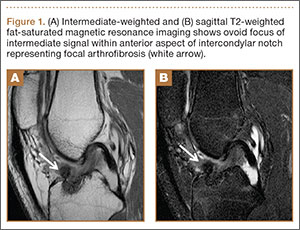
MRI can be used to accurately determine the position of the femoral and tibial tunnels. Correct femoral tunnel position results in isometry of the graft during full ROM of the knee. Graft impingement can occur when the tibial tunnel is placed too far anteriorly such that the graft contacts the roof of the intercondylar notch before the knee is able to fully extend.7 A tibial tunnel placed anterior to the intersection of the Blumensaat line and the tibia is at higher risk for impingement.1,4 Impingement may be accompanied by signal change in the graft on intermediate-weighted and fluid-sensitive sequences. The signal abnormality is usually focal and persists longer than the expected signal changes related to revascularization of immature grafts within the first year (Figure 2). If left untreated, impingement may progress to graft rupture.4
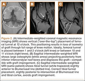
Complete graft rupture is diagnosed on the basis of discontinuity of the graft fibers. MRI findings include fluid-filled defect or absence of intact graft fibers. Other reliable signs include large joint effusion, anterior tibial translation, pivot-shift–type marrow edema pattern, and horizontal orientation, laxity, or resorption of the graft fibers.1,8,9 The diagnosis of partial graft rupture may be challenging, as there are several other causes of increased graft signal, including revascularization (within 12 months after procedure), signal heterogeneity between individual bundles of hamstring grafts, and focal signal changes related to impingment (Figures 3, 4).
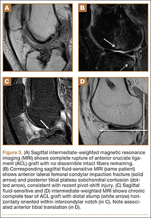
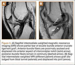
Fluid within the tunnels is a normal finding after surgery and typically resolves within the first 18 months.1 Cyst formation within the tibial tunnel is an uncommon complication of ACL-R and may be incidental to or present with clinical symptoms caused by extension into the pretibial soft tissues or expansion of the tunnel (Figure 5). Communication of cyst with joint space is important, as a noncommunicating cyst requires simple excision without need for bone grafting.7

Hardware-related complications (eg, loosening of fixation devices) are uncommon but may require revision surgery (Figure 6). Septic arthritis after ACL-R has a cumulative incidence of 0.1% to 0.9% and may be difficult to diagnose clinically because of the lack of classic symptoms of a septic joint.1 Diagnosis requires joint aspiration.

MRI is reliably and accurately used to assess ACL-R complications. The clinical history helps in stratifying complications that result in decreased ROM or increased laxity.
1. Bencardino JT, Beltran J, Feldman MI, Rose DJ. MR imaging of complications of anterior cruciate ligament graft reconstruction. Radiographics. 2009;29(7):2115-2126.
2. Recht MP, Kramer J. MR imaging of the postoperative knee: a pictorial essay. Radiographics. 2002;22(4):765-774.
3. Papakonstantinou O, Chung CB, Chanchairujira K, Resnick DL. Complications of anterior cruciate ligament reconstruction: MR imaging. Eur Radiol. 2003;13(5):1106-1117.
4. Meyers AB, Haims AH, Menn K, Moukaddam H. Imaging of anterior cruciate ligament repair and its complications. AJR Am J Roentgenol. 2010;194(2):476-484.
5. Kwok CS, Harrison T, Servant C. The optimal timing for anterior cruciate ligament reconstruction with respect to the risk of postoperative stiffness. Arthroscopy. 2013;29(3):556-565.
6. Mayr HO, Weig TG, Plitz W. Arthrofibrosis following ACL reconstruction—reasons and outcome. Arch Orthop Trauma Surg. 2004;124(8):518-522.
7. Ghazikhanian V, Beltran J, Nikac V, Feldman M, Bencardino JT. Tibial tunnel and pretibial cysts following ACL graft reconstruction: MR imaging diagnosis. Skeletal Radiol. 2012;41(11):1375-1379.
8. Collins MS, Unruh KP, Bond JR, Mandrekar JN. Magnetic resonance imaging of surgically confirmed anterior cruciate ligament graft disruption. Skeletal Radiol. 2008;37(3):233-243.
9. Saupe N, White LM, Chiavaras MM, et al. Anterior cruciate ligament reconstruction grafts: MR imaging features at long-term follow-up—correlation with functional and clinical evaluation. Radiology. 2008;249(2):581-590.
Magnetic resonance imaging (MRI) is the preferred modality in the evaluation of complications of anterior cruciate ligament reconstruction (ACL-R).1-3 ACL-R complications may be broadly characterized as those resulting in decreased range of motion (ROM), eg, arthrofibrosis and impingement, and those resulting in increased laxity, ie, graft disruption.4 Short tau inversion recovery (STIR) sequences best minimize artifact related to field inhomogeneity in the presence of metal-containing fixation devices. Patients with contraindications to MRI may undergo high-resolution computed tomographic arthrography of the knee for evaluation of postoperative graft abnormalities.1
Arthrofibrosis refers to focal or diffuse synovial scar tissue, which may limit ROM. Preoperative irritation, preoperative limited ROM, and reconstruction within 4 weeks of trauma may all play a role in the development of arthrofibrosis.5,6 The focal form, cyclops lesion, named for its arthroscopic appearance, has been reported in 1% to 10% of patients with ACL-R.1 On MRI, focal arthrofibrosis may be seen as a focal or diffuse intermediate signal lesion in the anterior intercondylar notch extending linearly along the intercondylar roof1 (Figure 1).
MRI can be used to accurately determine the position of the femoral and tibial tunnels. Correct femoral tunnel position results in isometry of the graft during full ROM of the knee. Graft impingement can occur when the tibial tunnel is placed too far anteriorly such that the graft contacts the roof of the intercondylar notch before the knee is able to fully extend.7 A tibial tunnel placed anterior to the intersection of the Blumensaat line and the tibia is at higher risk for impingement.1,4 Impingement may be accompanied by signal change in the graft on intermediate-weighted and fluid-sensitive sequences. The signal abnormality is usually focal and persists longer than the expected signal changes related to revascularization of immature grafts within the first year (Figure 2). If left untreated, impingement may progress to graft rupture.4
Complete graft rupture is diagnosed on the basis of discontinuity of the graft fibers. MRI findings include fluid-filled defect or absence of intact graft fibers. Other reliable signs include large joint effusion, anterior tibial translation, pivot-shift–type marrow edema pattern, and horizontal orientation, laxity, or resorption of the graft fibers.1,8,9 The diagnosis of partial graft rupture may be challenging, as there are several other causes of increased graft signal, including revascularization (within 12 months after procedure), signal heterogeneity between individual bundles of hamstring grafts, and focal signal changes related to impingment (Figures 3, 4).
Fluid within the tunnels is a normal finding after surgery and typically resolves within the first 18 months.1 Cyst formation within the tibial tunnel is an uncommon complication of ACL-R and may be incidental to or present with clinical symptoms caused by extension into the pretibial soft tissues or expansion of the tunnel (Figure 5). Communication of cyst with joint space is important, as a noncommunicating cyst requires simple excision without need for bone grafting.7
Hardware-related complications (eg, loosening of fixation devices) are uncommon but may require revision surgery (Figure 6). Septic arthritis after ACL-R has a cumulative incidence of 0.1% to 0.9% and may be difficult to diagnose clinically because of the lack of classic symptoms of a septic joint.1 Diagnosis requires joint aspiration.
MRI is reliably and accurately used to assess ACL-R complications. The clinical history helps in stratifying complications that result in decreased ROM or increased laxity.
1. Bencardino JT, Beltran J, Feldman MI, Rose DJ. MR imaging of complications of anterior cruciate ligament graft reconstruction. Radiographics. 2009;29(7):2115-2126.
2. Recht MP, Kramer J. MR imaging of the postoperative knee: a pictorial essay. Radiographics. 2002;22(4):765-774.
3. Papakonstantinou O, Chung CB, Chanchairujira K, Resnick DL. Complications of anterior cruciate ligament reconstruction: MR imaging. Eur Radiol. 2003;13(5):1106-1117.
4. Meyers AB, Haims AH, Menn K, Moukaddam H. Imaging of anterior cruciate ligament repair and its complications. AJR Am J Roentgenol. 2010;194(2):476-484.
5. Kwok CS, Harrison T, Servant C. The optimal timing for anterior cruciate ligament reconstruction with respect to the risk of postoperative stiffness. Arthroscopy. 2013;29(3):556-565.
6. Mayr HO, Weig TG, Plitz W. Arthrofibrosis following ACL reconstruction—reasons and outcome. Arch Orthop Trauma Surg. 2004;124(8):518-522.
7. Ghazikhanian V, Beltran J, Nikac V, Feldman M, Bencardino JT. Tibial tunnel and pretibial cysts following ACL graft reconstruction: MR imaging diagnosis. Skeletal Radiol. 2012;41(11):1375-1379.
8. Collins MS, Unruh KP, Bond JR, Mandrekar JN. Magnetic resonance imaging of surgically confirmed anterior cruciate ligament graft disruption. Skeletal Radiol. 2008;37(3):233-243.
9. Saupe N, White LM, Chiavaras MM, et al. Anterior cruciate ligament reconstruction grafts: MR imaging features at long-term follow-up—correlation with functional and clinical evaluation. Radiology. 2008;249(2):581-590.
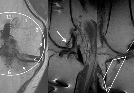
Increased prevalence of pancreatic cysts due to MRI improvements
The apparent increase in the prevalence of incidental pancreatic cysts in recent years may be tied to improvements in MRI scanning technology, results of a study suggest.
Researchers conducted a retrospective analysis of data from 500 patients who underwent an MRI for nonpancreatic indications at a single center between 2005 and 2014; 50 were sampled from each year in chronological order.

A total of 208 patients (41.6%) were found to have an incidental cyst, of which less than a quarter were described in the original MRI report, according to a paper published online in Clinical Gastroenterology and Hepatology.
Analysis showed a very strong association between the type of imaging hardware and software, and the presence of cysts; older hardware found pancreatic cysts in 30.3% of patients and the newest hardware found cysts in 56.3% of patients.
However, MRI field strength was not associated with the frequency of lesion discovery (Clin Gastro Hepatol. 2015 Sep 11. doi: 10.1016/j.cgh.2015.08.038).
Most cysts were relatively small, with a median size of 4 mm. Nearly half of the patients with a cyst only had one described.
Nearly two-thirds of these cysts (62%) had an uncertain diagnosis, but 35% of patients were diagnosed with an intraductal papillary mucinous neoplasm, and one patient showed radiologic evidence of subacute pancreatitis.
When compared to the rest of the cohort, individuals with pancreatic cysts were more likely to be older, have diabetes mellitus, or have a personal history of cancer, particularly nonmelanoma skin cancer and hepatocellular carcinoma.
“Our study demonstrates the relationship between the higher trend of incidental pancreatic cysts observed in the recent years and the improvements in the technical features of MRIs,” wrote Dr. Maria Moris and colleagues from the Mayo Clinic, Jacksonville.
The authors said the real prevalence of pancreatic cystic lesions is estimated to range from 0.2% to 44.7%.
Their finding of a prevalence of 41.6% was higher than that found in similar imaging studies, but the authors suggested some of this may be due to the lack of a size cutoff in their study, as opposed to a 5-mm cutoff used in one earlier study that found a prevalence of 10%.
“Moreover, we believe that we may have even underestimated the real prevalence because of the absence of magnetic resonance cholangiopancreatography sequences (only 19% of the examinations), and the lack of 3-T studies (6% of the MRIs),” they wrote.
The median size of the lesions was lower than those found in previous studies.
“This smaller size was unexpected because, as a result of the exclusion criteria applied, the technical features of the MRIs were not the most specific for [pancreatic cystic lesion] PCL visualization,” the authors wrote, suggesting that this may have been due to the radiologist’s experience in this field.
The study was funded by the Joyce E. Baker Foundation for Research at Mayo Clinic in Jacksonville. One author disclosed grants or travel support from Olympus, Boston Scientific, and Cosmo Pharmaceuticals. There were no other conflicts of interest declared.
The apparent increase in the prevalence of incidental pancreatic cysts in recent years may be tied to improvements in MRI scanning technology, results of a study suggest.
Researchers conducted a retrospective analysis of data from 500 patients who underwent an MRI for nonpancreatic indications at a single center between 2005 and 2014; 50 were sampled from each year in chronological order.
A total of 208 patients (41.6%) were found to have an incidental cyst, of which less than a quarter were described in the original MRI report, according to a paper published online in Clinical Gastroenterology and Hepatology.
Analysis showed a very strong association between the type of imaging hardware and software, and the presence of cysts; older hardware found pancreatic cysts in 30.3% of patients and the newest hardware found cysts in 56.3% of patients.
However, MRI field strength was not associated with the frequency of lesion discovery (Clin Gastro Hepatol. 2015 Sep 11. doi: 10.1016/j.cgh.2015.08.038).
Most cysts were relatively small, with a median size of 4 mm. Nearly half of the patients with a cyst only had one described.
Nearly two-thirds of these cysts (62%) had an uncertain diagnosis, but 35% of patients were diagnosed with an intraductal papillary mucinous neoplasm, and one patient showed radiologic evidence of subacute pancreatitis.
When compared to the rest of the cohort, individuals with pancreatic cysts were more likely to be older, have diabetes mellitus, or have a personal history of cancer, particularly nonmelanoma skin cancer and hepatocellular carcinoma.
“Our study demonstrates the relationship between the higher trend of incidental pancreatic cysts observed in the recent years and the improvements in the technical features of MRIs,” wrote Dr. Maria Moris and colleagues from the Mayo Clinic, Jacksonville.
The authors said the real prevalence of pancreatic cystic lesions is estimated to range from 0.2% to 44.7%.
Their finding of a prevalence of 41.6% was higher than that found in similar imaging studies, but the authors suggested some of this may be due to the lack of a size cutoff in their study, as opposed to a 5-mm cutoff used in one earlier study that found a prevalence of 10%.
“Moreover, we believe that we may have even underestimated the real prevalence because of the absence of magnetic resonance cholangiopancreatography sequences (only 19% of the examinations), and the lack of 3-T studies (6% of the MRIs),” they wrote.
The median size of the lesions was lower than those found in previous studies.
“This smaller size was unexpected because, as a result of the exclusion criteria applied, the technical features of the MRIs were not the most specific for [pancreatic cystic lesion] PCL visualization,” the authors wrote, suggesting that this may have been due to the radiologist’s experience in this field.
The study was funded by the Joyce E. Baker Foundation for Research at Mayo Clinic in Jacksonville. One author disclosed grants or travel support from Olympus, Boston Scientific, and Cosmo Pharmaceuticals. There were no other conflicts of interest declared.
FROM CLINICAL GASTROENTEROLOGY AND HEPATOLOGY
Key clinical point: The apparent increase of the prevalence of incidental pancreatic cysts in recent years may be tied to improvements in MRI scanning technology.
Major finding: Older MRI hardware found pancreatic cysts in 30.3% of patients and the newest hardware found cysts in 56.3% of patients.
Data source: A retrospective analysis of data from 500 patients who underwent an MRI for nonpancreatic indications.
Disclosures: The study was funded by the Joyce E. Baker Foundation for Research at Mayo Clinic in Jacksonville, Fla. One author disclosed grants or travel support from Olympus, Boston Scientific, and Cosmo Pharmaceuticals. There were no other conflicts of interest declared.
Emergency Ultrasound: Renal Evaluation
Background
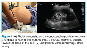
Technique
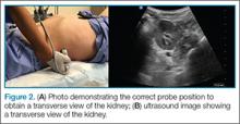
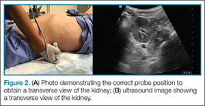
The study is performed with a curvilinear probe placed in the left and right midaxillary region along the lower costal margin. To obtain a longitudinal view of the kidneys, the probe marker should point toward the head of the bed (Figure 1). The clinician should then slide the probe until the kidney comes into view just caudal to either the liver on the right or the spleen on the left. It is important to remember that the kidneys are retroperitoneal; as such, the probe should be pointed toward the bed to ensure visualization.
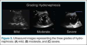
Hydronephrosis
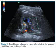

Ureteral or bladder outlet obstruction can lead to unilateral or bilateral renal hydronephrosis, which can present on a spectrum ranging from mild to severe. As fluid appears black on ultrasound, hydronephrosis will appear black in what is normally an echogenic center of the kidney. The higher the degree of hydronephrosis, the larger the area of black; in cases of severe hydronephrosis, there is thinning of the renal parenchyma and most of the kidney is taken up by dilated calyces (Figure 3). If there is uncertainty during evaluation, color Doppler may be employed to differentiate the vascular renal hilum from hydronephrosis (Figure 4).
Ureteral Stones
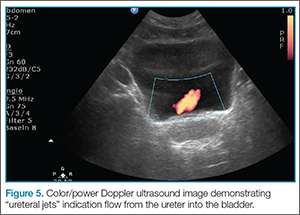
Ureteral stones are not typically visualized by ultrasound. However, intrarenal stones can be found. These will appear as hyperechoic structures within the central area of the kidney with acoustic shadowing artifact noted underneath them. Additionally, while scanning the bladder, one can sometimes find a stone lodged in the ureteropelvic junction (UPJ). One can also look for “ureteral jets,” seen as periodic flow of urine within the bladder using color/power Doppler (Figure 5).
Pearls/Pitfalls

Dr Meer is an assistant professor and director of emergency ultrasound, department of emergency medicine, Emory University School of Medicine, Atlanta, Georgia. Dr Beck is an assistant professor, department of emergency medicine, Emory University School of Medicine, Atlanta, Georgia. Dr Taylor is an assistant professor and director of postgraduate medical education, department of emergency medicine, Emory University School of Medicine, Atlanta, Georgia.
- Smith-Bindman R, Aubin C, Bailitz J, et al. Ultrasonography versus computed tomography for suspected nephrolithiasis. N Engl J Med. 2014;371(12):1100-1110.
Background
Technique
The study is performed with a curvilinear probe placed in the left and right midaxillary region along the lower costal margin. To obtain a longitudinal view of the kidneys, the probe marker should point toward the head of the bed (Figure 1). The clinician should then slide the probe until the kidney comes into view just caudal to either the liver on the right or the spleen on the left. It is important to remember that the kidneys are retroperitoneal; as such, the probe should be pointed toward the bed to ensure visualization.
Hydronephrosis
Ureteral or bladder outlet obstruction can lead to unilateral or bilateral renal hydronephrosis, which can present on a spectrum ranging from mild to severe. As fluid appears black on ultrasound, hydronephrosis will appear black in what is normally an echogenic center of the kidney. The higher the degree of hydronephrosis, the larger the area of black; in cases of severe hydronephrosis, there is thinning of the renal parenchyma and most of the kidney is taken up by dilated calyces (Figure 3). If there is uncertainty during evaluation, color Doppler may be employed to differentiate the vascular renal hilum from hydronephrosis (Figure 4).
Ureteral Stones
Ureteral stones are not typically visualized by ultrasound. However, intrarenal stones can be found. These will appear as hyperechoic structures within the central area of the kidney with acoustic shadowing artifact noted underneath them. Additionally, while scanning the bladder, one can sometimes find a stone lodged in the ureteropelvic junction (UPJ). One can also look for “ureteral jets,” seen as periodic flow of urine within the bladder using color/power Doppler (Figure 5).
Pearls/Pitfalls
Dr Meer is an assistant professor and director of emergency ultrasound, department of emergency medicine, Emory University School of Medicine, Atlanta, Georgia. Dr Beck is an assistant professor, department of emergency medicine, Emory University School of Medicine, Atlanta, Georgia. Dr Taylor is an assistant professor and director of postgraduate medical education, department of emergency medicine, Emory University School of Medicine, Atlanta, Georgia.
- Smith-Bindman R, Aubin C, Bailitz J, et al. Ultrasonography versus computed tomography for suspected nephrolithiasis. N Engl J Med. 2014;371(12):1100-1110.
- Smith-Bindman R, Aubin C, Bailitz J, et al. Ultrasonography versus computed tomography for suspected nephrolithiasis. N Engl J Med. 2014;371(12):1100-1110.
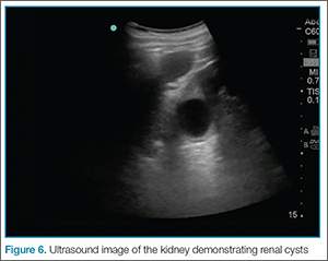
Case Report: An Unusual Case of Morel-Lavallée Lesion of the Upper Extremity
Case
A 32-year-old previously healthy woman presented to the ED with right upper arm pain and swelling of 6 days duration. According to the patient, the swelling began 2 days after she sustained a work-related injury at a coin-manufacturing factory. She stated that her right arm had gotten caught inside of a rolling press while she was cleaning it. The roller had stopped over her upper arm, trapping it between the roller and the platform for several minutes before it was extricated. She was brought to the ED by emergency medical services for evaluation immediately following this incident. At this first visit to the ED, the patient complained of mild pain in her right arm. Physical examination at that time revealed mild diffuse swelling extending from her hand to her distal humerus, with mild pain on passive flexion, and extension without associated numbness or tingling. Plain films of her right upper extremity were ordered, the results of which were relatively unremarkable. She was evaluated by an orthopedist, who ruled out compartment syndrome based on her benign physical examination and soft compartments. She was ultimately discharged and told to follow up with her primary care provider.
Over the course of 48 hours from the first ED visit, the patient developed large bullae on the dorsal and volar aspect of her forearm, elbow, and upper arm with associated pain. In addition to dark discolorations of the skin over her affected arm, she noticed that the bullae had become numerous and discolored. These symptoms continued to grow progressively worse, prompting her second presentation to the ED.
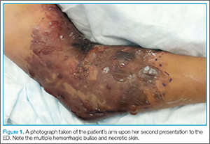
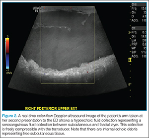
The patient was taken to the operating room and underwent debridement and resection of the circumferential necrotic skin and subcutaneous tissue in her right arm, and the placement of a skin graft with overlying wound vacuum-assisted closure. During the procedure, a large amount of serosanguinous fluid was drained and cultured, and was found to be sterile. Due to the size of her injury, she underwent two additional episodes of debridement and graft placement over the course of the next 2 weeks.
Discussion
First described in the 1850s by the French physician Maurice Morel-Lavallée, Morel-Lavallée lesion is a rare, traumatic, soft-tissue injury.1 It is an internal degloving injury wherein the skin and subcutaneous tissue have been forcibly separated from the underlying fascia as a result of shear stress. The lymphatic and blood vessels between the layers are also disrupted in this process, resulting in the accumulation of blood and lymphatic fluid as well as subcutaneous debris in the potential space that forms. Excess accumulation over time can compromise blood supply to the overlying skin and cause necrosis.2 Morel-Lavallée lesion is missed on initial evaluation in up to one-third of the cases and may have a delay in presentation ranging from hours to months after the inciting injury.3
Morel-Lavallée lesions typically involve the flank, hips, thigh, and prepatellar regions as a result of shear injuries sustained from bicycle falls and motor vehicle accidents.4 These lesions are often associated with concomitant acetabular and pelvic fractures.5 Involvement of the upper extremities is unusual. Typically, presentation consists of a fluctuant and painful mass underneath the skin which increases over time. The overlying skin may show the mechanism of the original injury, for example, as abrasions after a crush injury. The excessive skin necrosis and hemorrhagic bullae seen in this particular case is a very rare presentation.
Differential Diagnosis
The differential diagnosis includes compartment syndrome, coma blisters, a missed fracture, bullous pemphigoid, bullous drug reactions, and linear immunoglobulin A disease. Most of these conditions were easily ruled out in this case as the patient was previously healthy and not on any medications. The lesions in this case could have been confused with coma blisters, which are similar in appearance, self-limiting, and can develop on the extremities. However, coma blisters are classically associated with toxicity from various central nervous system depressants, as well as reduced consciousness from other causes—all of which were readily ruled-out based on the patient’s history. Moreover, the Morel-Lavallée lesion is a degloving injury of the subcutaneous tissue from the fascia underneath, whereas the pathology of coma blisters includes subepidermal bullae formation as well as immunoglobulin and complement deposition.6
Diagnostic Imaging
Morel-Lavallée lesion can often be confirmed via several imaging modalities, including ultrasound, CT, 3D CT, or magnetic resonance imaging (MRI).3,7 Ultrasound will usually show a well-circumscribed hypoechoic fluid collection with hyperechoic fat globules from the subcutaneous tissue, whereas CT tends to show an encapsulated mass with fluid collection underneath. In MRI, Morel-Lavallée lesion often appears as a hypointense T1-sequence and hyperintense T2-sequence similar to most other fluid collections. There may be variable T1- and T2-intensities with subcutaneous tissues in the fluid collection.2
Management
Despite recognition of this disease entity, controversies still exist regarding management. Case reports have demonstrated a relatively high rate of infected fluid collections depending on the chronicity of the injury.8 A recent algorithm to management described by Nickerson et al4 proposes that for patients with viable skin, percutaneous aspiration of more than 50 cc of fluid from these lesions should be treated with more extensive operative intervention based on the increased likelihood of recurrence. Patients without viable skin require formal debridement with possible skin grafting.
Other treatment options include conservative management, surgical drainage, sclerodesis, and extensive open surgery.8-10 Management is always case-based and dependent upon the size of the lesion and associated injuries.
Conclusion
This case represents an example of Morel-Lavallée lesions in their most severe and atypical form. It also serves as a reminder that vigilance and knowledge of this disease process is important in helping to diagnose this rare but potentially devastating condition. The key to recognizing this injury lies in keeping this disease process in the differential diagnosis of traumatic injuries with suspicious mechanism involving significant shear forces. Significant physical examination findings may not be present initially and evolve over a time period of hours to days. Once this injury is identified, management hinges on the size of the lesion and affected body part. Despite timely interventions, Morel-Lavallée lesions may result in significant morbidity and functional disability.
Dr Ye is an emergency medicine resident at the Brown Alpert Medical School in Providence, Rhode Island. Dr Rosenberg is a clinical assistant professor at Brown Alpert Medical School, and an emergency medicine attending physican at Rhode Island Hospital and The Miriam Hospital, Providence, Rhode Island.
- Morel-Lavallée M. Epanchements traumatique de serosite. Arc Générales Méd. 1853;691-731.
- Chokshi F, Jose J, Clifford P. Morel Lavallée Lesion. Am J Orthop (Belle Mead NJ). 2010;39(5): 252-253.
- Bonilla-Yoon I, Masih S, Patel DB, et al. The Morel-Lavallée lesion: pathophysiology, clinical presentation, imaging features, and treatment options. Emerg Radiol. 2014;21(1):35-43.
- Nickerson T, Zielinski M, Jenkins D, Schiller HJ. The Mayo Clinic experience with Morel-Lavallée lesions: establishment of a practice management guideline. J Trauma Acute Care Surg. 2014:76(2);493-497.
- Powers ML, Hatem SF, Sundaram M. Morel-Lavallee lesion. Orthopedics. 2007;30(4):322-323.
- Agarwal A, Bansal M, Conner K. Coma blisters with hypoxemic respiratory failure. Dermatol Online Journal. 2012:18(3);10.
- Reddix RN, Carrol E, Webb LX. Early diagnosis of a Morel-Lavallee lesion using three-dimensional computed tomography reconstructions: a case report. J Trauma. 2009;67(2):e57-e59.
- Lin HL, Lee WC, Kuo LC, Chen CW. Closed internal degloving injury with conservative treatment. Am J Emerg Med. 2008:26(2);254.e5-e6.
- Luria S, Applbaum Y,Weil Y, Liebergall M, Peyser A. Talc sclerodhesis of persistent Morel-Lavallée lesions (posttraumatic pseudocysts): case report of 4 patients. J Orthop Trauma. 2006;20(6):435-438.
- Penaud A, Quignon R, Danin A, Bahé L, Zakine G. Alcohol sclerodhesis: an innovative treatment for chronic Morel-Lavallée lesions. J Plast Reconstr Aesthet Surg. 2011;64(10): e262-264.
Case
A 32-year-old previously healthy woman presented to the ED with right upper arm pain and swelling of 6 days duration. According to the patient, the swelling began 2 days after she sustained a work-related injury at a coin-manufacturing factory. She stated that her right arm had gotten caught inside of a rolling press while she was cleaning it. The roller had stopped over her upper arm, trapping it between the roller and the platform for several minutes before it was extricated. She was brought to the ED by emergency medical services for evaluation immediately following this incident. At this first visit to the ED, the patient complained of mild pain in her right arm. Physical examination at that time revealed mild diffuse swelling extending from her hand to her distal humerus, with mild pain on passive flexion, and extension without associated numbness or tingling. Plain films of her right upper extremity were ordered, the results of which were relatively unremarkable. She was evaluated by an orthopedist, who ruled out compartment syndrome based on her benign physical examination and soft compartments. She was ultimately discharged and told to follow up with her primary care provider.
Over the course of 48 hours from the first ED visit, the patient developed large bullae on the dorsal and volar aspect of her forearm, elbow, and upper arm with associated pain. In addition to dark discolorations of the skin over her affected arm, she noticed that the bullae had become numerous and discolored. These symptoms continued to grow progressively worse, prompting her second presentation to the ED.
The patient was taken to the operating room and underwent debridement and resection of the circumferential necrotic skin and subcutaneous tissue in her right arm, and the placement of a skin graft with overlying wound vacuum-assisted closure. During the procedure, a large amount of serosanguinous fluid was drained and cultured, and was found to be sterile. Due to the size of her injury, she underwent two additional episodes of debridement and graft placement over the course of the next 2 weeks.
Discussion
First described in the 1850s by the French physician Maurice Morel-Lavallée, Morel-Lavallée lesion is a rare, traumatic, soft-tissue injury.1 It is an internal degloving injury wherein the skin and subcutaneous tissue have been forcibly separated from the underlying fascia as a result of shear stress. The lymphatic and blood vessels between the layers are also disrupted in this process, resulting in the accumulation of blood and lymphatic fluid as well as subcutaneous debris in the potential space that forms. Excess accumulation over time can compromise blood supply to the overlying skin and cause necrosis.2 Morel-Lavallée lesion is missed on initial evaluation in up to one-third of the cases and may have a delay in presentation ranging from hours to months after the inciting injury.3
Morel-Lavallée lesions typically involve the flank, hips, thigh, and prepatellar regions as a result of shear injuries sustained from bicycle falls and motor vehicle accidents.4 These lesions are often associated with concomitant acetabular and pelvic fractures.5 Involvement of the upper extremities is unusual. Typically, presentation consists of a fluctuant and painful mass underneath the skin which increases over time. The overlying skin may show the mechanism of the original injury, for example, as abrasions after a crush injury. The excessive skin necrosis and hemorrhagic bullae seen in this particular case is a very rare presentation.
Differential Diagnosis
The differential diagnosis includes compartment syndrome, coma blisters, a missed fracture, bullous pemphigoid, bullous drug reactions, and linear immunoglobulin A disease. Most of these conditions were easily ruled out in this case as the patient was previously healthy and not on any medications. The lesions in this case could have been confused with coma blisters, which are similar in appearance, self-limiting, and can develop on the extremities. However, coma blisters are classically associated with toxicity from various central nervous system depressants, as well as reduced consciousness from other causes—all of which were readily ruled-out based on the patient’s history. Moreover, the Morel-Lavallée lesion is a degloving injury of the subcutaneous tissue from the fascia underneath, whereas the pathology of coma blisters includes subepidermal bullae formation as well as immunoglobulin and complement deposition.6
Diagnostic Imaging
Morel-Lavallée lesion can often be confirmed via several imaging modalities, including ultrasound, CT, 3D CT, or magnetic resonance imaging (MRI).3,7 Ultrasound will usually show a well-circumscribed hypoechoic fluid collection with hyperechoic fat globules from the subcutaneous tissue, whereas CT tends to show an encapsulated mass with fluid collection underneath. In MRI, Morel-Lavallée lesion often appears as a hypointense T1-sequence and hyperintense T2-sequence similar to most other fluid collections. There may be variable T1- and T2-intensities with subcutaneous tissues in the fluid collection.2
Management
Despite recognition of this disease entity, controversies still exist regarding management. Case reports have demonstrated a relatively high rate of infected fluid collections depending on the chronicity of the injury.8 A recent algorithm to management described by Nickerson et al4 proposes that for patients with viable skin, percutaneous aspiration of more than 50 cc of fluid from these lesions should be treated with more extensive operative intervention based on the increased likelihood of recurrence. Patients without viable skin require formal debridement with possible skin grafting.
Other treatment options include conservative management, surgical drainage, sclerodesis, and extensive open surgery.8-10 Management is always case-based and dependent upon the size of the lesion and associated injuries.
Conclusion
This case represents an example of Morel-Lavallée lesions in their most severe and atypical form. It also serves as a reminder that vigilance and knowledge of this disease process is important in helping to diagnose this rare but potentially devastating condition. The key to recognizing this injury lies in keeping this disease process in the differential diagnosis of traumatic injuries with suspicious mechanism involving significant shear forces. Significant physical examination findings may not be present initially and evolve over a time period of hours to days. Once this injury is identified, management hinges on the size of the lesion and affected body part. Despite timely interventions, Morel-Lavallée lesions may result in significant morbidity and functional disability.
Dr Ye is an emergency medicine resident at the Brown Alpert Medical School in Providence, Rhode Island. Dr Rosenberg is a clinical assistant professor at Brown Alpert Medical School, and an emergency medicine attending physican at Rhode Island Hospital and The Miriam Hospital, Providence, Rhode Island.
- Morel-Lavallée M. Epanchements traumatique de serosite. Arc Générales Méd. 1853;691-731.
- Chokshi F, Jose J, Clifford P. Morel Lavallée Lesion. Am J Orthop (Belle Mead NJ). 2010;39(5): 252-253.
- Bonilla-Yoon I, Masih S, Patel DB, et al. The Morel-Lavallée lesion: pathophysiology, clinical presentation, imaging features, and treatment options. Emerg Radiol. 2014;21(1):35-43.
- Nickerson T, Zielinski M, Jenkins D, Schiller HJ. The Mayo Clinic experience with Morel-Lavallée lesions: establishment of a practice management guideline. J Trauma Acute Care Surg. 2014:76(2);493-497.
- Powers ML, Hatem SF, Sundaram M. Morel-Lavallee lesion. Orthopedics. 2007;30(4):322-323.
- Agarwal A, Bansal M, Conner K. Coma blisters with hypoxemic respiratory failure. Dermatol Online Journal. 2012:18(3);10.
- Reddix RN, Carrol E, Webb LX. Early diagnosis of a Morel-Lavallee lesion using three-dimensional computed tomography reconstructions: a case report. J Trauma. 2009;67(2):e57-e59.
- Lin HL, Lee WC, Kuo LC, Chen CW. Closed internal degloving injury with conservative treatment. Am J Emerg Med. 2008:26(2);254.e5-e6.
- Luria S, Applbaum Y,Weil Y, Liebergall M, Peyser A. Talc sclerodhesis of persistent Morel-Lavallée lesions (posttraumatic pseudocysts): case report of 4 patients. J Orthop Trauma. 2006;20(6):435-438.
- Penaud A, Quignon R, Danin A, Bahé L, Zakine G. Alcohol sclerodhesis: an innovative treatment for chronic Morel-Lavallée lesions. J Plast Reconstr Aesthet Surg. 2011;64(10): e262-264.

An alerting sign: Enlarged cardiac silhouette
A 75-year-old woman with a history of hypertension and left-lung lobectomy for a carcinoid tumor 10 years ago presented with a 2-week history of progressive cough, dyspnea, and fatigue. Her heart rate was 159 beats per minute with an irregularly irregular rhythm, and her respiratory rate was 36 breaths per minute. Her blood pressure was 140/90 mm Hg. Examination revealed decreased breath sounds and dullness on percussion at the left lung base, jugular venous distention with a positive hepatojugular reflux sign, and an enlarged liver. Electrocardiography showed atrial fibrillation. Chest radiography (Figure 1) revealed enlargement of the cardiac silhouette, with a disproportionately increased transverse diameter, and an obscured left costophrenic angle. A radiograph taken 13 months earlier (Figure 1) had shown a normal cardiothoracic ratio.
EVALUATION OF PERICARDIAL EFFUSION

Pericardial effusion should be suspected in patients presenting with symptoms of impaired cardiac function such as fatigue, dyspnea, nausea, palpitations, lightheadedness, cough, and hoarseness. Patients may also present with chest pain, often decreased by sitting up and leaning forward and exacerbated by lying supine.
Physical examination may reveal distant heart sounds, an absent or displaced apical impulse, dullness and increased fremitus beneath the angle of the left scapula (the Ewart sign), pulsus paradoxus, and nonspecific findings such as tachycardia and hypotension. Jugular venous distention, hepatojugular reflux, and peripheral edema suggest impaired cardiac function.
A chest radiograph showing unexplained new symmetric cardiomegaly (which is often globe-shaped) without signs of pulmonary congestion1 or with a left dominant pleural effusion is an indicator of pericardial effusion, as in our patient. Pericardial fluid may be seen outlining the heart between the epicardial and mediastinal fat, posterior to the sternum in a lateral view.
Other common causes of cardiomegaly include hypertension, congestive heart failure, valvular disease, cardiomyopathy, ischemic heart disease, and pulmonary disease.
Once pericardial effusion is suspected, the next step is to confirm its presence and determine its hemodynamic significance. Transthoracic echocardiography is the imaging test of choice to confirm effusion, as it can be done rapidly and in unstable patients.2
If transthoracic echocardiography is nondiagnostic but suspicion is high, further evaluation may include transesophageal echocardiography,3 computed tomography, or magnetic resonance imaging.
MAKING THE DIAGNOSIS
Pericardial effusion can occur as part of various diseases involving the pericardium, eg, acute pericarditis, myocarditis, autoimmune disease, postmyocardial infarction, malignancy, aortic dissection, and chest trauma. It can also be associated with certain drugs.
In our patient, echocardiography (Figure 2, Figure 3) demonstrated a large amount of pericardial fluid, and 820 mL of red fluid was aspirated by pericardiocentesis, resulting in relief of her respiratory symptoms. Subcostal two-dimensional echocardiography demonstrated rocking of the heart and intermittent right-ventricular collapse (watch video at www.ccjm.org). Flow cytometry demonstrated 10% kappa+ monoclonal cells. Bone marrow biopsy with immunohistochemical staining revealed infiltration by CD20+, CD5+, CD23+, and BCL1– cells, compatible with small lymphocytic lymphoma.
MALIGNANT PERICARDIAL EFFUSION
Pericardial disease can be the first manifestation of malignancy,4 more often when the patient presents with a large pericardial effusion or tamponade. Malignant tumors of the lung, breast, and esophagus—as well as lymphoma, leukemia, and melanoma—often spread to the pericardium directly or through the lymphatic vessels or bloodstream.4 In our patient, corticosteroid treatment was initiated, and echocardiography at a follow-up visit 2 months later showed no pericardial fluid.
- Khandaker MH, Espinosa RE, Nishimura RA, et al. Pericardial disease: diagnosis and management. Mayo Clin Proc 2010; 85:572–593.
- Cheitlin MD, Armstrong WF, Aurigemma GP, et al; American College of Cardiology; American Heart Association; American Society of Echocardiography. ACC/AHA/ASE 2003 guideline update for the clinical application of echocardiography: summary article: a report of the American College of Cardiology/American Heart Association Task Force on Practice Guidelines (ACC/AHA/ASE Committee to Update the 1997 Guidelines for the Clinical Application of Echocardiography). Circulation 2003; 108:1146–1162.
- Verhaert D, Gabriel RS, Johnston D, Lytle BW, Desai MY, Klein AL. The role of multimodality imaging in the management of pericardial disease. Circ Cardiovascular Imaging 2010; 3:333–343.
- Burazor I, Imazio M, Markel G, Adler Y. Malignant pericardial effusion. Cardiology 2013; 124:224–232.
A 75-year-old woman with a history of hypertension and left-lung lobectomy for a carcinoid tumor 10 years ago presented with a 2-week history of progressive cough, dyspnea, and fatigue. Her heart rate was 159 beats per minute with an irregularly irregular rhythm, and her respiratory rate was 36 breaths per minute. Her blood pressure was 140/90 mm Hg. Examination revealed decreased breath sounds and dullness on percussion at the left lung base, jugular venous distention with a positive hepatojugular reflux sign, and an enlarged liver. Electrocardiography showed atrial fibrillation. Chest radiography (Figure 1) revealed enlargement of the cardiac silhouette, with a disproportionately increased transverse diameter, and an obscured left costophrenic angle. A radiograph taken 13 months earlier (Figure 1) had shown a normal cardiothoracic ratio.
EVALUATION OF PERICARDIAL EFFUSION
Pericardial effusion should be suspected in patients presenting with symptoms of impaired cardiac function such as fatigue, dyspnea, nausea, palpitations, lightheadedness, cough, and hoarseness. Patients may also present with chest pain, often decreased by sitting up and leaning forward and exacerbated by lying supine.
Physical examination may reveal distant heart sounds, an absent or displaced apical impulse, dullness and increased fremitus beneath the angle of the left scapula (the Ewart sign), pulsus paradoxus, and nonspecific findings such as tachycardia and hypotension. Jugular venous distention, hepatojugular reflux, and peripheral edema suggest impaired cardiac function.
A chest radiograph showing unexplained new symmetric cardiomegaly (which is often globe-shaped) without signs of pulmonary congestion1 or with a left dominant pleural effusion is an indicator of pericardial effusion, as in our patient. Pericardial fluid may be seen outlining the heart between the epicardial and mediastinal fat, posterior to the sternum in a lateral view.
Other common causes of cardiomegaly include hypertension, congestive heart failure, valvular disease, cardiomyopathy, ischemic heart disease, and pulmonary disease.
Once pericardial effusion is suspected, the next step is to confirm its presence and determine its hemodynamic significance. Transthoracic echocardiography is the imaging test of choice to confirm effusion, as it can be done rapidly and in unstable patients.2
If transthoracic echocardiography is nondiagnostic but suspicion is high, further evaluation may include transesophageal echocardiography,3 computed tomography, or magnetic resonance imaging.
MAKING THE DIAGNOSIS
Pericardial effusion can occur as part of various diseases involving the pericardium, eg, acute pericarditis, myocarditis, autoimmune disease, postmyocardial infarction, malignancy, aortic dissection, and chest trauma. It can also be associated with certain drugs.
In our patient, echocardiography (Figure 2, Figure 3) demonstrated a large amount of pericardial fluid, and 820 mL of red fluid was aspirated by pericardiocentesis, resulting in relief of her respiratory symptoms. Subcostal two-dimensional echocardiography demonstrated rocking of the heart and intermittent right-ventricular collapse (watch video at www.ccjm.org). Flow cytometry demonstrated 10% kappa+ monoclonal cells. Bone marrow biopsy with immunohistochemical staining revealed infiltration by CD20+, CD5+, CD23+, and BCL1– cells, compatible with small lymphocytic lymphoma.
MALIGNANT PERICARDIAL EFFUSION
Pericardial disease can be the first manifestation of malignancy,4 more often when the patient presents with a large pericardial effusion or tamponade. Malignant tumors of the lung, breast, and esophagus—as well as lymphoma, leukemia, and melanoma—often spread to the pericardium directly or through the lymphatic vessels or bloodstream.4 In our patient, corticosteroid treatment was initiated, and echocardiography at a follow-up visit 2 months later showed no pericardial fluid.
- Khandaker MH, Espinosa RE, Nishimura RA, et al. Pericardial disease: diagnosis and management. Mayo Clin Proc 2010; 85:572–593.
- Cheitlin MD, Armstrong WF, Aurigemma GP, et al; American College of Cardiology; American Heart Association; American Society of Echocardiography. ACC/AHA/ASE 2003 guideline update for the clinical application of echocardiography: summary article: a report of the American College of Cardiology/American Heart Association Task Force on Practice Guidelines (ACC/AHA/ASE Committee to Update the 1997 Guidelines for the Clinical Application of Echocardiography). Circulation 2003; 108:1146–1162.
- Verhaert D, Gabriel RS, Johnston D, Lytle BW, Desai MY, Klein AL. The role of multimodality imaging in the management of pericardial disease. Circ Cardiovascular Imaging 2010; 3:333–343.
- Burazor I, Imazio M, Markel G, Adler Y. Malignant pericardial effusion. Cardiology 2013; 124:224–232.