User login
Ischiofemoral Impingement and the Utility of Full-Range-of-Motion Magnetic Resonance Imaging in Its Detection
With the first cases described in 1977, ischiofemoral impingement (IFI) is a relatively recently discovered and less known potential cause of hip pain caused by compression on the quadratus femoris muscle (QFM).1-10 These first patients, who were treated with surgical excision of the lesser trochanter, experienced symptom improvement in all 3 cases.5,7 The most widely accepted diagnostic criteria use a combination of clinical and imaging findings.1-10 Criteria most often cited in the literature include isolated edema-like signal in the QFM on magnetic resonance imaging (MRI) and ipsilateral hip pain without a known cause, such as recent trauma or infection.4,5 All studies describe QFM compression occurring as the muscle passes between the lesser trochanter of the femur and the origin of the ischial tuberosity/hamstring tendons.1-10
Several authors have sought to improve diagnostic accuracy by providing various measurements to quantify the probability of impingement.5,7,9 Although groups have proposed different thresholds, our institution currently uses values reported by Tosun and colleagues5 because theirs is the most robust sample size to date and included 50 patients with IFI.7,9 Although 5 different measurements were proposed, 2 are more commonly cited. The first is the ischiofemoral space (IFS), which is the most narrow distance between the cortex of the lesser trochanter and the cortex of the ischial tuberosity. This space should normally be greater than 1.8 cm.5 The second measurement is called the quadratus femoris space (QFS) and is the most narrow distance between the hamstring tendons and either the iliopsoas tendon or the cortex of the lesser trochanter. The QFS should normally be greater than 1.0 cm.5 However, because these measurements may depend on the hip position during imaging, full-range-of-motion (FROM) MRI may increase diagnostic yield. At our institution, patients are usually imaged supine in neutral position (with respect to internal or external rotation).
In this article, we briefly review IFI, provide an example of how FROM MRI can improve diagnostic accuracy, describe our FROM protocol, and propose an expanded definition of the impingement criteria. The patient provided written informed consent for print and electronic publication of the case details and images.
Full–Range-of-Motion MRI Technique
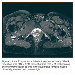
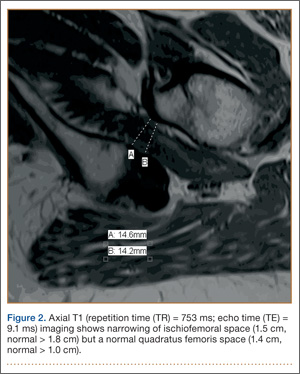
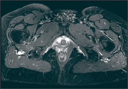
A 58-year-old woman with no surgical history or diagnosed inflammatory arthropathy presented to the department of physical medicine and rehabilitation with left-buttock pain radiating down the left thigh. Despite nonsurgical management with nonsteroidal anti-inflammatory medication, exercise therapy, use of a transcutaneous electrical nerve stimulator unit, and oral corticosteroid therapy, the pain continued. The patient was referred for MRI, and routine static imaging of the pelvis was performed. Although edema-like signal was present in both QFMs (Figure 1), left more than right, the measurement of the QFS and IFS did not meet all criteria for narrowing as described in previous studies. On the symptomatic left side, the IFS measured 1.5 cm and the QFS measured 1.4 cm (Figure 2). On the same side, the distance between the cortex of the greater trochanter and the cortex of the ischial tuberosity, proposed adapted IFS, measured 1.4 cm, and the distance between the cortex of the greater trochanter and the hamstring tendons origin, proposed adapted QFS, measured 1.1 cm (Figure 3). However, because of the isolated QFM edema, refractory buttock and thigh pain, and exclusion of other diagnoses (such as labral tear, bone marrow edema/stress reaction in the hip, or MRI findings of sciatic neuropathy), we determined that the patient needed evaluation of the QFS and the IFS through a full range of motion. The patient returned for the FROM MRI 16 days after the initial static MRI.
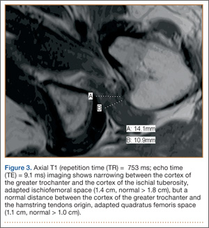
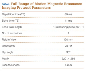
Our FROM MRI was performed on a Magnetom Skyra 3 Tesla magnet (Seimens Healthcare Global, Munich, Germany), using a body array 18-channel coil and a table spine coil. In a supine position, the patient’s imaging started with the hip in extension, adduction, and approximately 20º of internal rotation. During imaging acquisition, the patient was maintained in adduction and extension while the hip was passively externally rotated (Figure 3). A technologist assisted the patient in maintaining the position through a 60º arc of external rotation, while an axial-gradient echo sequence was used to obtain sequential images through the entire arc. Selected parameters are listed in the Table. Acquisition of the arc of motion in the axial plane requires approximately 3 minutes per hip to generate between 8 and 10 images.
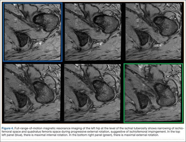
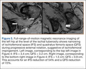
With the patient’s hip in internal rotation, narrowing between the ischium or hamstring tendons and the lesser trochanter did not meet all of the criteria described by Tosun and colleagues5 or Torriani and colleagues.7 However, when the patient shifted into external rotation, the distance between the ischial tuberosity and the greater trochanter, and between the hamstring tendons origin and the greater trochanter, significantly narrowed. The adapted IFS decreased from 3.4 cm to 1.5 cm, and the adapted QFS decreased from 3.2 cm to 0.9 cm, accounting for a 54% and 72% reduction of the adapted IFS and QFS, respectively, with maximum external rotation (Figures 4, 5).
Discussion
While femoroacetabular impingement is a widely recognized and sometimes surgically treated syndrome, IFI may be overlooked as a cause of hip pain. Although IFI is traditionally described as mass effect on the QFM by the ischium/hamstring tendons origin and the lesser trochanter, we propose expansion of this criteria to include narrowing resulting from the greater trochanter in external rotation as a potential source of impingement. By use of FROM MRI, we adapted measurements previously described for IFI to evaluate for compression of the QFM by adjacent osseous and tendinous structures throughout the full range of internal/external hip rotation. In this case, FROM imaging provided evidence of possible anatomical narrowing caused by the greater trochanter, in addition to that caused by the lesser trochanter. Given that impingement may be caused by either the greater or lesser trochanters, it is prudent to perform FROM MRI in evaluating patients with suspected IFI. If FROM imaging is not feasible, static imaging in both maximal internal and external rotation may allow for better assessment. There have been no large studies conducted to assess the normal interval between the ischial tuberosity/hamstring origins and the greater trochanter.
The purpose of this report is to call attention to a source of impingement that may be undetected with static MRI, possibly leading to a missed diagnosis. While we believe this to be the first reported example of impingement involving the greater trochanter, larger studies should be conducted to explore this possible source of impingement. Information about the incidence of greater trochanteric impingement could lead to changes in our understanding of this syndrome and its management.
1. Lee S, Kim I, Lee SM, Lee J. Ischiofemoral impingement syndrome. Ann Rehabil Med. 2013;37(1):143-146.
2. Sussman WI, Han E, Schuenke MD. Quantitative assessment of the ischiofemoral space and evidence of degenerative changes in the quadratus femoris muscle. Surg Radiol Anat. 2013;35(4):273-281.
3. López-Sánchez MC, Armesto Pérez V, Montero Furelos LÁ, Vázquez-Rodríguez TR, Calvo Arrojo G, Díaz Román TM. Ischiofemoral impingement: hip pain of infrequent cause. Ischiofemoral impingement: hip pain of infrequent cause. Rheumatol Clin. 2013;9(3):186-187.
4. Viala P, Vanel D, Larbi A, Cyteval C, Laredo JD. Bilateral ischiofemoral impingement in a patient with hereditary multiple exostoses. Skeletal Radiol. 2012;41(12):1637-1640.
5. Tosun O, Algin O, Yalcin N, Cay N, Ocakoglu G, Karaoglanoglu M. Ischiofemoral impingement: evaluation with new MRI parameters and assessment of their reliability. Skeletal Radiol. 2012;41(5):575-587.
6. Ali AM, Whitwell D, Ostlere SJ. Case report: imaging and surgical treatment of a snapping hip due to ischiofemoral impingement. Skeletal Radiol. 2011;40(5):653-656.
7. Torriani M, Souto SC, Thomas BJ, Ouellette H, Bredella MA. Ischiofemoral impingement syndrome: an entity with hip pain and abnormalities of the quadratus femoris muscle. AJR Am J Roentgenol. 2009;193(1):186-190.
8. Ali AM, Teh J, Whitwell D, Ostlere S. Ischiofemoral impingement: a retrospective analysis of cases in a specialist orthopaedic centre over a four-year period. Hip Int. 2013;3(23):263-268.
9. Sussman WI, Han E, Schuenke MD. Quantitative assessment of the ischiofemoral space and evidence of degenerative changes in the quadratus femoris muscle. Surg Radiol Anat. 2013;35(4):273-281.
10. Kassarjian A. Signal abnormalities in the quadratus femoris muscle: tear or impingement? AJR Am J Roentgenol. 2008;190(6):W379.
With the first cases described in 1977, ischiofemoral impingement (IFI) is a relatively recently discovered and less known potential cause of hip pain caused by compression on the quadratus femoris muscle (QFM).1-10 These first patients, who were treated with surgical excision of the lesser trochanter, experienced symptom improvement in all 3 cases.5,7 The most widely accepted diagnostic criteria use a combination of clinical and imaging findings.1-10 Criteria most often cited in the literature include isolated edema-like signal in the QFM on magnetic resonance imaging (MRI) and ipsilateral hip pain without a known cause, such as recent trauma or infection.4,5 All studies describe QFM compression occurring as the muscle passes between the lesser trochanter of the femur and the origin of the ischial tuberosity/hamstring tendons.1-10
Several authors have sought to improve diagnostic accuracy by providing various measurements to quantify the probability of impingement.5,7,9 Although groups have proposed different thresholds, our institution currently uses values reported by Tosun and colleagues5 because theirs is the most robust sample size to date and included 50 patients with IFI.7,9 Although 5 different measurements were proposed, 2 are more commonly cited. The first is the ischiofemoral space (IFS), which is the most narrow distance between the cortex of the lesser trochanter and the cortex of the ischial tuberosity. This space should normally be greater than 1.8 cm.5 The second measurement is called the quadratus femoris space (QFS) and is the most narrow distance between the hamstring tendons and either the iliopsoas tendon or the cortex of the lesser trochanter. The QFS should normally be greater than 1.0 cm.5 However, because these measurements may depend on the hip position during imaging, full-range-of-motion (FROM) MRI may increase diagnostic yield. At our institution, patients are usually imaged supine in neutral position (with respect to internal or external rotation).
In this article, we briefly review IFI, provide an example of how FROM MRI can improve diagnostic accuracy, describe our FROM protocol, and propose an expanded definition of the impingement criteria. The patient provided written informed consent for print and electronic publication of the case details and images.
Full–Range-of-Motion MRI Technique
A 58-year-old woman with no surgical history or diagnosed inflammatory arthropathy presented to the department of physical medicine and rehabilitation with left-buttock pain radiating down the left thigh. Despite nonsurgical management with nonsteroidal anti-inflammatory medication, exercise therapy, use of a transcutaneous electrical nerve stimulator unit, and oral corticosteroid therapy, the pain continued. The patient was referred for MRI, and routine static imaging of the pelvis was performed. Although edema-like signal was present in both QFMs (Figure 1), left more than right, the measurement of the QFS and IFS did not meet all criteria for narrowing as described in previous studies. On the symptomatic left side, the IFS measured 1.5 cm and the QFS measured 1.4 cm (Figure 2). On the same side, the distance between the cortex of the greater trochanter and the cortex of the ischial tuberosity, proposed adapted IFS, measured 1.4 cm, and the distance between the cortex of the greater trochanter and the hamstring tendons origin, proposed adapted QFS, measured 1.1 cm (Figure 3). However, because of the isolated QFM edema, refractory buttock and thigh pain, and exclusion of other diagnoses (such as labral tear, bone marrow edema/stress reaction in the hip, or MRI findings of sciatic neuropathy), we determined that the patient needed evaluation of the QFS and the IFS through a full range of motion. The patient returned for the FROM MRI 16 days after the initial static MRI.
Our FROM MRI was performed on a Magnetom Skyra 3 Tesla magnet (Seimens Healthcare Global, Munich, Germany), using a body array 18-channel coil and a table spine coil. In a supine position, the patient’s imaging started with the hip in extension, adduction, and approximately 20º of internal rotation. During imaging acquisition, the patient was maintained in adduction and extension while the hip was passively externally rotated (Figure 3). A technologist assisted the patient in maintaining the position through a 60º arc of external rotation, while an axial-gradient echo sequence was used to obtain sequential images through the entire arc. Selected parameters are listed in the Table. Acquisition of the arc of motion in the axial plane requires approximately 3 minutes per hip to generate between 8 and 10 images.
With the patient’s hip in internal rotation, narrowing between the ischium or hamstring tendons and the lesser trochanter did not meet all of the criteria described by Tosun and colleagues5 or Torriani and colleagues.7 However, when the patient shifted into external rotation, the distance between the ischial tuberosity and the greater trochanter, and between the hamstring tendons origin and the greater trochanter, significantly narrowed. The adapted IFS decreased from 3.4 cm to 1.5 cm, and the adapted QFS decreased from 3.2 cm to 0.9 cm, accounting for a 54% and 72% reduction of the adapted IFS and QFS, respectively, with maximum external rotation (Figures 4, 5).
Discussion
While femoroacetabular impingement is a widely recognized and sometimes surgically treated syndrome, IFI may be overlooked as a cause of hip pain. Although IFI is traditionally described as mass effect on the QFM by the ischium/hamstring tendons origin and the lesser trochanter, we propose expansion of this criteria to include narrowing resulting from the greater trochanter in external rotation as a potential source of impingement. By use of FROM MRI, we adapted measurements previously described for IFI to evaluate for compression of the QFM by adjacent osseous and tendinous structures throughout the full range of internal/external hip rotation. In this case, FROM imaging provided evidence of possible anatomical narrowing caused by the greater trochanter, in addition to that caused by the lesser trochanter. Given that impingement may be caused by either the greater or lesser trochanters, it is prudent to perform FROM MRI in evaluating patients with suspected IFI. If FROM imaging is not feasible, static imaging in both maximal internal and external rotation may allow for better assessment. There have been no large studies conducted to assess the normal interval between the ischial tuberosity/hamstring origins and the greater trochanter.
The purpose of this report is to call attention to a source of impingement that may be undetected with static MRI, possibly leading to a missed diagnosis. While we believe this to be the first reported example of impingement involving the greater trochanter, larger studies should be conducted to explore this possible source of impingement. Information about the incidence of greater trochanteric impingement could lead to changes in our understanding of this syndrome and its management.
1. Lee S, Kim I, Lee SM, Lee J. Ischiofemoral impingement syndrome. Ann Rehabil Med. 2013;37(1):143-146.
2. Sussman WI, Han E, Schuenke MD. Quantitative assessment of the ischiofemoral space and evidence of degenerative changes in the quadratus femoris muscle. Surg Radiol Anat. 2013;35(4):273-281.
3. López-Sánchez MC, Armesto Pérez V, Montero Furelos LÁ, Vázquez-Rodríguez TR, Calvo Arrojo G, Díaz Román TM. Ischiofemoral impingement: hip pain of infrequent cause. Ischiofemoral impingement: hip pain of infrequent cause. Rheumatol Clin. 2013;9(3):186-187.
4. Viala P, Vanel D, Larbi A, Cyteval C, Laredo JD. Bilateral ischiofemoral impingement in a patient with hereditary multiple exostoses. Skeletal Radiol. 2012;41(12):1637-1640.
5. Tosun O, Algin O, Yalcin N, Cay N, Ocakoglu G, Karaoglanoglu M. Ischiofemoral impingement: evaluation with new MRI parameters and assessment of their reliability. Skeletal Radiol. 2012;41(5):575-587.
6. Ali AM, Whitwell D, Ostlere SJ. Case report: imaging and surgical treatment of a snapping hip due to ischiofemoral impingement. Skeletal Radiol. 2011;40(5):653-656.
7. Torriani M, Souto SC, Thomas BJ, Ouellette H, Bredella MA. Ischiofemoral impingement syndrome: an entity with hip pain and abnormalities of the quadratus femoris muscle. AJR Am J Roentgenol. 2009;193(1):186-190.
8. Ali AM, Teh J, Whitwell D, Ostlere S. Ischiofemoral impingement: a retrospective analysis of cases in a specialist orthopaedic centre over a four-year period. Hip Int. 2013;3(23):263-268.
9. Sussman WI, Han E, Schuenke MD. Quantitative assessment of the ischiofemoral space and evidence of degenerative changes in the quadratus femoris muscle. Surg Radiol Anat. 2013;35(4):273-281.
10. Kassarjian A. Signal abnormalities in the quadratus femoris muscle: tear or impingement? AJR Am J Roentgenol. 2008;190(6):W379.
Ultrasound plus transthoracic echocardiography speeds CVC placement
AUSTIN, TEX. – Ultrasound plus real-time transthoracic echocardiography sped up placements of central venous catheters and rule outs of insertion-related pneumothorax, compared with ultrasound alone in a prospective, randomized, controlled study of 60 patients in the medical intensive care unit of a single center.
Compared to conventional ultrasound placement with x-ray confirmation, ultrasound plus transthoracic echocardiography also reduced the time to approval of the line for use, Dr. Dileep Raman reported at the annual meeting of the American College of Chest Physicians.
Waiting for a chest x-ray adds anywhere from 16 minutes to 2 hours to the approval of line use, according to the literature. Ultrasound is “a cheap bedside tool that can be repeatedly used to reduce the amount of chest x-rays for line placement and insertion” and indeed reduced the need for chest x-ray to confirm central venous catheter (CVC) position – without adding to procedure time, he said.
In the study, ultrasound plus transthoracic echocardiography reduced the use of bedside chest x-rays by 57% in 30 patients, compared with conventional ultrasound placement with x-ray confirmation in 29 patients. The mean time to line use was 25 minutes in the ultrasound plus echo group and 53.6 minutes in the conventional placement group, said Dr. Raman of the Cleveland Clinic.
The mean time to complete the procedure was 24.1 minutes in the intervention group, compared with 27.7 minutes in the x-ray confirmation group, he said. None of the study patients had pneumothoraces.
Study subjects were consecutive patients admitted to an intensive care unit at a tertiary care medical center. Both the intervention and control groups had central venous catheters inserted under ultrasound guidance, but the intervention group underwent real-time transthoracic echocardiography to assist in catheter positioning, as well as chest ultrasonography to exclude a pneumothorax. After this process was completed, the line was immediately cleared for use. If the catheter wasn’t detected in the right atrium, the patient was switched to the control group, which was treated using conventional techniques followed by standard chest x-ray.
The study groups were well matched with respect to age, body mass index, and APACHE III score.
Obtaining a chest x-ray to confirm line placement and to exclude pneumothorax remains the standard of care in most ICUs, but Dr. Raman said he and his colleagues dispute that chest x-ray should remain the standard, as it doesn’t identify the superior vena cava–right atrium junction. Also, in addition to reducing the need for chest x-ray, the ultrasound technique seems to give a better picture of line placement.
Additional studies are needed to look at safety and feasibility, because pneumothorax rates are low, and “60 patients is clearly not enough to see if we dented the pneumothorax rate,” he said.
Dr. Raman reported having no disclosures.
Key clinical point: The use of ultrasound and transthoracic echocardiography for CVC placement reduces the need for chest x-ray confirmation.
Major finding: The use of bedside chest x-ray was reduced by 57% with ultrasound plus real-time transthoracic echocardiography.
Data source: A prospective, randomized, controlled study of 60 patients.
Disclosures: Dr. Raman reported having no disclosures.
Annual echo an option for cardiac allograft vasculopathy screening
LAS VEGAS – The experience at one major heart transplantation center indicates that annual screening dobutamine stress echocardiography to detect cardiac allograft vasculopathy renders annual coronary angiography unnecessary.
“This noninvasive method has very good specificity and is associated with a negative predictive value of 94%-97%. It can be used in our experience in lieu of annual invasive coronary angiography,” Dr. Jerry D. Estep declared at the annual meeting of the Heart Failure Society of America.

Cardiac allograft vasculopathy (CAV) is a unique, highly aggressive form of CAD. After 3 years post transplant it becomes the No. 1 cause of cardiac retransplantation and mortality. Guidelines recommend consideration of annual screening coronary angiography to detect it early to institute aggressive countermeasures. That’s the practice at most transplant centers.
However, at Houston Methodist Hospital, where Dr. Estep is medical director of the heart transplant and LVAD program, annual dobutamine stress echocardiography (DSE) is used instead. Because there is a scarcity of published data on this noninvasive alternative approach, he presented a retrospective study of the Houston transplant center’s experience over a recent 5-year period.
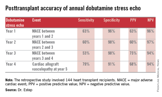
The study included 144 heart transplant recipients who underwent screening DSE for CAV annually for the first 4 years post transplant and coronary angiography at year 5.
During years 1-4, DSE detected CAV in 19% of patients. They didn’t differ in terms of baseline characteristics from those who remained free of this serious complication.
The good news: Ninety-four percent of patients with normal DSEs during years 1-4 had no CAV upon angiography at year 5. Moreover, the 5% who did have CAV at year 5 after earlier negative DSEs had mild to moderate disease.
The investigators documented the performance of annual screening DSE in predicting the development of major adverse cardiac events, defined as readmission for acute coronary syndrome, heart failure, revascularization, repeat heart transplantation, or cardiac death.
Dr. Estep reported having no financial conflicts regarding this study.
Dr. Hossein Almassi, FCCP, comments: Among solid organ transplants, cardiac transplant is rather unique in its need for invasive biopsy and angiography in following up the cardiac allograft. The search for noninvasive monitoring tools has been ongoing for a number of years. The report by the Houston group is a positive development in the right direction awaiting further confirmation by other cardiac transplant centers.
Dr. Almassi specializes in cardiothoracic surgery at the Medical College of Wisconsin in Milwaukee, Wisconsin.
LAS VEGAS – The experience at one major heart transplantation center indicates that annual screening dobutamine stress echocardiography to detect cardiac allograft vasculopathy renders annual coronary angiography unnecessary.
“This noninvasive method has very good specificity and is associated with a negative predictive value of 94%-97%. It can be used in our experience in lieu of annual invasive coronary angiography,” Dr. Jerry D. Estep declared at the annual meeting of the Heart Failure Society of America.
Cardiac allograft vasculopathy (CAV) is a unique, highly aggressive form of CAD. After 3 years post transplant it becomes the No. 1 cause of cardiac retransplantation and mortality. Guidelines recommend consideration of annual screening coronary angiography to detect it early to institute aggressive countermeasures. That’s the practice at most transplant centers.
However, at Houston Methodist Hospital, where Dr. Estep is medical director of the heart transplant and LVAD program, annual dobutamine stress echocardiography (DSE) is used instead. Because there is a scarcity of published data on this noninvasive alternative approach, he presented a retrospective study of the Houston transplant center’s experience over a recent 5-year period.
The study included 144 heart transplant recipients who underwent screening DSE for CAV annually for the first 4 years post transplant and coronary angiography at year 5.
During years 1-4, DSE detected CAV in 19% of patients. They didn’t differ in terms of baseline characteristics from those who remained free of this serious complication.
The good news: Ninety-four percent of patients with normal DSEs during years 1-4 had no CAV upon angiography at year 5. Moreover, the 5% who did have CAV at year 5 after earlier negative DSEs had mild to moderate disease.
The investigators documented the performance of annual screening DSE in predicting the development of major adverse cardiac events, defined as readmission for acute coronary syndrome, heart failure, revascularization, repeat heart transplantation, or cardiac death.
Dr. Estep reported having no financial conflicts regarding this study.
AT THE HFSA ANNUAL SCIENTIFIC MEETING
Key clinical point: Annual dobutamine stress echocardiography to screen heart transplant recipients for cardiac allograft vasculopathy is an excellent noninvasive alternative to the widely used practice of annual screening coronary angiography.
Major finding: Annual screening dobutamine stress echo during years 1-4 after heart transplant had a 94% negative predictive value for cardiac allograft vasculopathy at year 5.
Data source: A retrospective study of 144 heart transplant recipients at a major transplant center where screening for cardiac allograft vasculopathy is done noninvasively by annual dobutamine stress echocardiography rather than angiography, which is widely used elsewhere.
Disclosures: The presenter reported having no conflicts relevant to the study, which was free of commercial support.

Nonobstructive CAD increases risk of MI and death
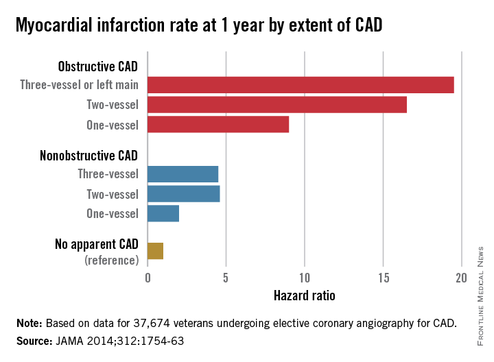
Patients with nonobstructive coronary artery disease are at significantly greater risk of myocardial infarction and all-cause mortality than are those with no CAD, and research is needed to explore risk mitigation methods in this group, say the authors of a retrospective cohort study.
The study of 37,674 U.S. veterans undergoing elective coronary angiography for CAD found patients with one-vessel nonobstructive CAD were at double the risk of a MI within 1 year, compared with those with no apparent CAD (see chart), and showed a 60% increase in mortality among individuals with three-vessel nonobstructive CAD.

“The 1-year MI risk progressively increased by CAD extent, rather than abruptly increasing between nonobstructive and obstructive CAD,” wrote Dr. Thomas M. Maddox of the Denver Veterans Affairs Medical Center and his colleagues, in an article published online Nov. 4 (JAMA 2014;312:1754-63 [doi:10.1001/jama.2014.14681]). [However] empirical evidence is lacking as to whether these patients benefit from the prevention therapies recommended for their obstructive CAD counterparts.”
The study was supported by the Department of Veterans Affairs Office of Information and Analytics. Authors declared a variety of funding, directorships, and committee positions in public and private industry.
Patients with nonobstructive coronary artery disease are at significantly greater risk of myocardial infarction and all-cause mortality than are those with no CAD, and research is needed to explore risk mitigation methods in this group, say the authors of a retrospective cohort study.
The study of 37,674 U.S. veterans undergoing elective coronary angiography for CAD found patients with one-vessel nonobstructive CAD were at double the risk of a MI within 1 year, compared with those with no apparent CAD (see chart), and showed a 60% increase in mortality among individuals with three-vessel nonobstructive CAD.
“The 1-year MI risk progressively increased by CAD extent, rather than abruptly increasing between nonobstructive and obstructive CAD,” wrote Dr. Thomas M. Maddox of the Denver Veterans Affairs Medical Center and his colleagues, in an article published online Nov. 4 (JAMA 2014;312:1754-63 [doi:10.1001/jama.2014.14681]). [However] empirical evidence is lacking as to whether these patients benefit from the prevention therapies recommended for their obstructive CAD counterparts.”
The study was supported by the Department of Veterans Affairs Office of Information and Analytics. Authors declared a variety of funding, directorships, and committee positions in public and private industry.
FROM JAMA
Key clinical point: Nonobstructive coronary artery disease is associated with a significant increase in the risk of myocardial infarction and death.
Major finding: Patients with nonobstructive coronary artery disease have between 2.0 and 4.6 times the MI risk than do those without CAD.
Data source: Retrospective cohort study of 37,674 U.S. veterans undergoing elective coronary angiography for coronary artery disease.
Disclosures: The study was supported by the Department of Veterans Affairs Office of Information and Analytics. Authors declared a variety of funding, directorships, and committee positions in public and private industry.
Aortic Dissection
Case
A 72-year-old man with a past medical history of hypertension and social history of tobacco use presented to the ED with chest pain and abdominal pain. His vital signs at presentation were: heart rate, 110 beats/minute; blood pressure, 80/40 mm Hg; respiratory rate, 22 breaths/minute; temperature, afebrile. His oxygen saturation was 98% on room air. The patient was alert and oriented; his abdomen was soft with no reproducible tenderness to palpation and without a palpable mass. The remainder of the physical examination was otherwise unremarkable. An electrocardiogram revealed sinus tachycardia with left ventricular hypertrophy, and a chest X-ray was read as no acute process by radiology services. Since the patient’s creatinine level was elevated at 3.5 mg/dL, the use of radiocontrast media relatively contraindicated.


To quickly assess the patient, the treating emergency physician (EP) performed a limited transabdominal ultrasound at the bedside, which revealed an intimal flap in the abdominal aorta in the transverse plane visible at the subcostal margin (Figure 1). The longitudinal view demonstrated the intimal flap clearly, but with no clear point of origin in the abdominal portion of the aorta (Figure 2).
The subcostal cardiac view also revealed the cause for the patient’s hemodynamic instability: a large pericardial effusion with evidence of early acute pericardial tamponade via right atrial collapse (Figure 3).
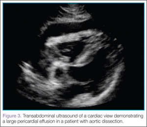
The patient was taken to the operating room within 20 minutes of arrival to the ED. Expedient diagnosis of both the presence and extent of his aortic dissection and its complications by bedside ultrasound facilitated early and aggressive management of this life-threatening disease process.
Imaging Techniques
Abdominal Aorta
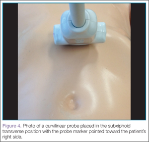
Ultrasound of the abdominal aorta begins with the use of a curvilinear probe, starting in the transverse plane with the probe marker pointing toward the patient’s right side (ie, the 9-o’clock position). The probe should scan the epigastrium, which is located just below the xiphoid process (Figure 4).
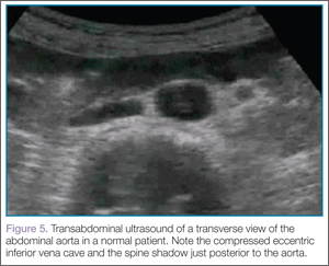
For orientation, the clinician should identify the vertebral body, which will appear as a dark and rounded object at the bottom center of the screen with a dark shadow behind it. Both the aorta and inferior vena cava (IVC) will be visualized just superficial to the vertebral body; the aorta typically appears anterior to the vertebral body, with the IVC slightly to the right of it. The amount of pressure applied for visualization of these structures will vary depending on the patient’s body habitus and volume status (Figure 5).
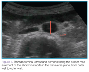
Once orientation is established and there is a clear transverse view of the aorta, calipers are used to measure the diameter of the aorta from superficial to deep, measuring from outer wall to outer wall (Figure 6).
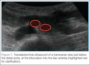
Next, the clinician should scan the probe caudally as he or she follows the aorta down to the level of the bifurcation into the iliac vessels, near the level of the umbilicus (Figure 7).
Then, rotating the probe clockwise 90˚ to place the probe marker in the 12-o’clock position, the abdominal aorta can be measured in the long axis, giving a broad overview of the entire structure (Figure 8).

Identification of an undulating intimal flap is highly specific for the diagnosis of aortic dissection.
Thoracic Aorta
After imaging of the abdominal aorta is complete, a phased array probe is used to scan the thoracic aorta, beginning with a subxiphoid view of the heart. The probe should be placed in the transverse plane, just inferior to the xiphoid process and with the probe marker aimed toward the patient’s right side (ie, the 9-o’clock position). Next, the probe is angled cephalad and slightly toward the patient’s left shoulder, nearly laying it flat on the abdomen, using the liver as the acoustic window. As with abdominal ultrasound, depending on the patient’s body habitus and anatomy, the depth may need to be adjusted for optimal view. This is one of the best views when evaluating for pericardial effusion, which will appear as a dark or anechoic stripe surrounding the heart (Figure 3).
After this view is complete, the clinician should proceed to scan the parasternal long axis view to evaluate the aortic outflow track and descending aorta. The cardiac probe should be placed in the left third or fourth intercostal space with the probe marker angled toward the patient’s right shoulder (ie, the 10- to 11-o’clock position). Proceeding from superficial to deep on the screen, the right ventricle, left ventricle and aortic outflow tract, left atrium, and then the descending aorta (Figure 9) will be visualized.
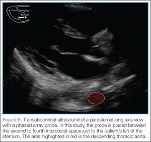
The two main areas to assess closely are the aortic outflow tract and the descending aorta. While looking at the aortic outflow tract, evidence of aortic regurgitation or a linear echodensity within the aortic root may be seen, suggestive of the intimal flap occurring in aortic dissection. Focusing on the descending aorta, the clinician should again look for a linear echodensity across the aorta, which represents the intimal flap (red highlighted area, Figure 9).
Discussion
Acute aortic dissection is an emergent, life-threatening condition with a high morbidity and mortality rate and a wide range of clinical manifestations and atypical presentations—all of which benefit from rapid identification. The combination of these factors makes diagnosis difficult, but all the more essential, especially considering the time-sensitivity of initiating treatment with intravenous antihypertensive agents and operative intervention.1
Bedside ultrasound provides a rapid and reliable method of making the diagnosis at the point of care, thus positively affecting patient care and outcome. Although existing research is limited, available data indicate that the EP can accurately diagnose acute aortic dissection and its complications using this modality.
Rapid diagnosis of aortic catastrophes at the bedside is not a novel concept. Shuman et al2 studied bedside transabdominal ultrasound on initial presentation of patients with severe abdominal or back pain, suspicious for abdominal aortic aneurysm (AAA). In this study of 60 patients, 31 of 32 AAAs were identified; these diagnoses were made prior to a surgeon’s evaluation.
More recently, Kuhn et al3 completed a similar study of EP use of beside ultrasound in the ED. Although their study lacked strength secondary to small sample size, it did indicate the ability to accurately determine the presence of an AAA with minimal training and experience.
Bedside Ultrasound Versus Other Imaging Modalities
There are multiple imaging modalities to consider when evaluating a patient with a possible aortic dissection, the decision of which should also take into account the ability to determine alternative diagnoses.
Bedside Ultrasound. This modality provides the EP with a quick, easy tool to evaluate multiple, potential life-threatening emergencies immediately at the bedside in a patient with suspected aortic dissection.4 Numerous studies have documented a sensitivity of 78% to 87% and a specificity of 99% to 100% for the diagnosis of aortic dissection by transthoracic and transabdominal ultrasound when an undulating intimal flap is visualized.5
Computed Tomography Angiography. In comparison to beside ultrasound, computed tomography angiography (CTA) has a sensitivity of 96% to 100% and a specificity of 96% to 100%.6,7 However, since CTA requires the use of iodinated contrast material, it is relatively contraindicated in the setting of acute kidney injury, a condition not uncommon in patients with acute aortic dissection.
Magnetic Resonance Imaging. Currently the gold standard for the identification of aortic dissection, magnetic resonance imaging has both a sensitivity and specificity of 98%.7,8 The major disadvantages of this test are the lack of availability and the length of the study itself.
Chest X-ray. A chest X-ray is commonly used as a screening test for aortic dissection, despite 12% to 20% of patients with aortic dissection having a “normal” X-ray.6
Transesophageal echocardiography. Another good modality for diagnosing aortic dissection is transesophageal echocardiography (TEE), which has a sensitivity of up to 98% and a specificity of up to 97%.8 This test, however, requires an experienced operator at the bedside, typically a cardiologist, and is an invasive study that requires the use of sedation and occasionally general anesthesia. A TEE is limited by its inability to visualize the descending aorta below the stomach.6-8
Conclusion
There are several benefits to using bedside ultrasound at the point of care to diagnose aortic dissection. This modality provides not only a rapid, noninvasive, and painless study requiring no radiocontrast media, but also has a high specificity for detection of aortic dissection. Moreover, it also allows the provider to evaluate for other potential life-threatening emergencies such as concomitant abdominal aortic aneurysm, intraperitoneal hemorrhage, pericardial effusion, and cardiac tamponade.9,10
Dr Venezia is a resident in the department of emergency medicine, Eastern Virginia Medical School, Norfolk. Dr Sawyer is a clinical instructor in the department of emergency medicine, Eastern Virginia Medical School, Norfolk. Dr Byars is an associate professor in the department of emergency medicine, Eastern Virginia Medical School, Norfolk.
For a video clip showing a transverse view of the abdominal aorta with the dissection flap clearly visible mid-lumen of the proximal aorta, visit https://vimeo.com/111462170.
For a video clip showing a longitudinal view of the abdominal aorta with the dissection flap clearly visible in the mid-lumen of the aorta, visit https://vimeo.com/111462168.
For a video clip of a cardiac view demonstrating large pericardial effusion in the patient with aortic dissection, visit https://vimeo.com/111462169.
For a video clip demonstrating ultrasound of the parasternal long axis view with a phased array probe, visit https://vimeo.com/111462167.
- Lo, BM. An evidence-based approach to acute aortic syndromes. Emerg Med Pract. 2013;15(12):1-23.
- Shuman WP, Hastrup W Jr, Kohler TR, et al. Suspected leaking abdominal aortic aneurysm: use of sonography in the emergency room. Radiology. 1988;168(1):117-119.
- Kuhn M, Bonnin RL, Davey MJ, Rowland JL, Langlois SL. Emergency department ultrasound scanning for abdominal aortic aneurysm: accessible, accurate, and advantageous. Ann Emerg Med. 2000;36(3):219-223.
- Fojtik JP, Costantino TG, Dean AJ. The diagnosis of aortic dissection by emergency medicine ultrasound. J Emerg Med. 2007;32(2):191-196.
- Brunson JM, Fine RL, Schussler JM. Acute ascending aortic dissection diagnosed with transthoracic echocardiography. J Am Soc Echo. 2009;22(9):1086.e5–1086.e7.
- Erbel R, Alfonso F, Boileau C, et al; Task Force on Aortic Dissection, European Society of Cardiology. Diagnosis and management of aortic dissection. Eur Heart J. 2001;22(18):1642-1681.
- Nienaber CA, von Kodolitsch Y, Nicolas V, et al. The diagnosis of thoracic aortic dissection by noninvasive imaging procedures. N Engl J Med. 1993;328(1):1-
- Nienaber CA, Eagle KA. Aortic dissection: new frontiers in diagnosis and management: Part I: from etiology to diagnostic strategies. Circulation. 2003;108(5):628-635.
- Goodman A, Perera P, Mailhot T, Mandavia D. The role of bedside ultrasound in the diagnosis of pericardial effusion and cardiac tamponade. J Emerg Trauma Shock. 2012;5(1):72-75.
- Perera P, Mailhot T, Riley D, Mandavia D. The RUSH exam: Rapid ultrasound in shock in the evaluation of the critically ill. Emerg Med Clin North Am. 2010;28(1):29-56.
Case
A 72-year-old man with a past medical history of hypertension and social history of tobacco use presented to the ED with chest pain and abdominal pain. His vital signs at presentation were: heart rate, 110 beats/minute; blood pressure, 80/40 mm Hg; respiratory rate, 22 breaths/minute; temperature, afebrile. His oxygen saturation was 98% on room air. The patient was alert and oriented; his abdomen was soft with no reproducible tenderness to palpation and without a palpable mass. The remainder of the physical examination was otherwise unremarkable. An electrocardiogram revealed sinus tachycardia with left ventricular hypertrophy, and a chest X-ray was read as no acute process by radiology services. Since the patient’s creatinine level was elevated at 3.5 mg/dL, the use of radiocontrast media relatively contraindicated.
To quickly assess the patient, the treating emergency physician (EP) performed a limited transabdominal ultrasound at the bedside, which revealed an intimal flap in the abdominal aorta in the transverse plane visible at the subcostal margin (Figure 1). The longitudinal view demonstrated the intimal flap clearly, but with no clear point of origin in the abdominal portion of the aorta (Figure 2).
The subcostal cardiac view also revealed the cause for the patient’s hemodynamic instability: a large pericardial effusion with evidence of early acute pericardial tamponade via right atrial collapse (Figure 3).
The patient was taken to the operating room within 20 minutes of arrival to the ED. Expedient diagnosis of both the presence and extent of his aortic dissection and its complications by bedside ultrasound facilitated early and aggressive management of this life-threatening disease process.
Imaging Techniques
Abdominal Aorta
Ultrasound of the abdominal aorta begins with the use of a curvilinear probe, starting in the transverse plane with the probe marker pointing toward the patient’s right side (ie, the 9-o’clock position). The probe should scan the epigastrium, which is located just below the xiphoid process (Figure 4).
For orientation, the clinician should identify the vertebral body, which will appear as a dark and rounded object at the bottom center of the screen with a dark shadow behind it. Both the aorta and inferior vena cava (IVC) will be visualized just superficial to the vertebral body; the aorta typically appears anterior to the vertebral body, with the IVC slightly to the right of it. The amount of pressure applied for visualization of these structures will vary depending on the patient’s body habitus and volume status (Figure 5).
Once orientation is established and there is a clear transverse view of the aorta, calipers are used to measure the diameter of the aorta from superficial to deep, measuring from outer wall to outer wall (Figure 6).
Next, the clinician should scan the probe caudally as he or she follows the aorta down to the level of the bifurcation into the iliac vessels, near the level of the umbilicus (Figure 7).
Then, rotating the probe clockwise 90˚ to place the probe marker in the 12-o’clock position, the abdominal aorta can be measured in the long axis, giving a broad overview of the entire structure (Figure 8).
Identification of an undulating intimal flap is highly specific for the diagnosis of aortic dissection.
Thoracic Aorta
After imaging of the abdominal aorta is complete, a phased array probe is used to scan the thoracic aorta, beginning with a subxiphoid view of the heart. The probe should be placed in the transverse plane, just inferior to the xiphoid process and with the probe marker aimed toward the patient’s right side (ie, the 9-o’clock position). Next, the probe is angled cephalad and slightly toward the patient’s left shoulder, nearly laying it flat on the abdomen, using the liver as the acoustic window. As with abdominal ultrasound, depending on the patient’s body habitus and anatomy, the depth may need to be adjusted for optimal view. This is one of the best views when evaluating for pericardial effusion, which will appear as a dark or anechoic stripe surrounding the heart (Figure 3).
After this view is complete, the clinician should proceed to scan the parasternal long axis view to evaluate the aortic outflow track and descending aorta. The cardiac probe should be placed in the left third or fourth intercostal space with the probe marker angled toward the patient’s right shoulder (ie, the 10- to 11-o’clock position). Proceeding from superficial to deep on the screen, the right ventricle, left ventricle and aortic outflow tract, left atrium, and then the descending aorta (Figure 9) will be visualized.
The two main areas to assess closely are the aortic outflow tract and the descending aorta. While looking at the aortic outflow tract, evidence of aortic regurgitation or a linear echodensity within the aortic root may be seen, suggestive of the intimal flap occurring in aortic dissection. Focusing on the descending aorta, the clinician should again look for a linear echodensity across the aorta, which represents the intimal flap (red highlighted area, Figure 9).
Discussion
Acute aortic dissection is an emergent, life-threatening condition with a high morbidity and mortality rate and a wide range of clinical manifestations and atypical presentations—all of which benefit from rapid identification. The combination of these factors makes diagnosis difficult, but all the more essential, especially considering the time-sensitivity of initiating treatment with intravenous antihypertensive agents and operative intervention.1
Bedside ultrasound provides a rapid and reliable method of making the diagnosis at the point of care, thus positively affecting patient care and outcome. Although existing research is limited, available data indicate that the EP can accurately diagnose acute aortic dissection and its complications using this modality.
Rapid diagnosis of aortic catastrophes at the bedside is not a novel concept. Shuman et al2 studied bedside transabdominal ultrasound on initial presentation of patients with severe abdominal or back pain, suspicious for abdominal aortic aneurysm (AAA). In this study of 60 patients, 31 of 32 AAAs were identified; these diagnoses were made prior to a surgeon’s evaluation.
More recently, Kuhn et al3 completed a similar study of EP use of beside ultrasound in the ED. Although their study lacked strength secondary to small sample size, it did indicate the ability to accurately determine the presence of an AAA with minimal training and experience.
Bedside Ultrasound Versus Other Imaging Modalities
There are multiple imaging modalities to consider when evaluating a patient with a possible aortic dissection, the decision of which should also take into account the ability to determine alternative diagnoses.
Bedside Ultrasound. This modality provides the EP with a quick, easy tool to evaluate multiple, potential life-threatening emergencies immediately at the bedside in a patient with suspected aortic dissection.4 Numerous studies have documented a sensitivity of 78% to 87% and a specificity of 99% to 100% for the diagnosis of aortic dissection by transthoracic and transabdominal ultrasound when an undulating intimal flap is visualized.5
Computed Tomography Angiography. In comparison to beside ultrasound, computed tomography angiography (CTA) has a sensitivity of 96% to 100% and a specificity of 96% to 100%.6,7 However, since CTA requires the use of iodinated contrast material, it is relatively contraindicated in the setting of acute kidney injury, a condition not uncommon in patients with acute aortic dissection.
Magnetic Resonance Imaging. Currently the gold standard for the identification of aortic dissection, magnetic resonance imaging has both a sensitivity and specificity of 98%.7,8 The major disadvantages of this test are the lack of availability and the length of the study itself.
Chest X-ray. A chest X-ray is commonly used as a screening test for aortic dissection, despite 12% to 20% of patients with aortic dissection having a “normal” X-ray.6
Transesophageal echocardiography. Another good modality for diagnosing aortic dissection is transesophageal echocardiography (TEE), which has a sensitivity of up to 98% and a specificity of up to 97%.8 This test, however, requires an experienced operator at the bedside, typically a cardiologist, and is an invasive study that requires the use of sedation and occasionally general anesthesia. A TEE is limited by its inability to visualize the descending aorta below the stomach.6-8
Conclusion
There are several benefits to using bedside ultrasound at the point of care to diagnose aortic dissection. This modality provides not only a rapid, noninvasive, and painless study requiring no radiocontrast media, but also has a high specificity for detection of aortic dissection. Moreover, it also allows the provider to evaluate for other potential life-threatening emergencies such as concomitant abdominal aortic aneurysm, intraperitoneal hemorrhage, pericardial effusion, and cardiac tamponade.9,10
Dr Venezia is a resident in the department of emergency medicine, Eastern Virginia Medical School, Norfolk. Dr Sawyer is a clinical instructor in the department of emergency medicine, Eastern Virginia Medical School, Norfolk. Dr Byars is an associate professor in the department of emergency medicine, Eastern Virginia Medical School, Norfolk.
For a video clip showing a transverse view of the abdominal aorta with the dissection flap clearly visible mid-lumen of the proximal aorta, visit https://vimeo.com/111462170.
For a video clip showing a longitudinal view of the abdominal aorta with the dissection flap clearly visible in the mid-lumen of the aorta, visit https://vimeo.com/111462168.
For a video clip of a cardiac view demonstrating large pericardial effusion in the patient with aortic dissection, visit https://vimeo.com/111462169.
For a video clip demonstrating ultrasound of the parasternal long axis view with a phased array probe, visit https://vimeo.com/111462167.
- Lo, BM. An evidence-based approach to acute aortic syndromes. Emerg Med Pract. 2013;15(12):1-23.
- Shuman WP, Hastrup W Jr, Kohler TR, et al. Suspected leaking abdominal aortic aneurysm: use of sonography in the emergency room. Radiology. 1988;168(1):117-119.
- Kuhn M, Bonnin RL, Davey MJ, Rowland JL, Langlois SL. Emergency department ultrasound scanning for abdominal aortic aneurysm: accessible, accurate, and advantageous. Ann Emerg Med. 2000;36(3):219-223.
- Fojtik JP, Costantino TG, Dean AJ. The diagnosis of aortic dissection by emergency medicine ultrasound. J Emerg Med. 2007;32(2):191-196.
- Brunson JM, Fine RL, Schussler JM. Acute ascending aortic dissection diagnosed with transthoracic echocardiography. J Am Soc Echo. 2009;22(9):1086.e5–1086.e7.
- Erbel R, Alfonso F, Boileau C, et al; Task Force on Aortic Dissection, European Society of Cardiology. Diagnosis and management of aortic dissection. Eur Heart J. 2001;22(18):1642-1681.
- Nienaber CA, von Kodolitsch Y, Nicolas V, et al. The diagnosis of thoracic aortic dissection by noninvasive imaging procedures. N Engl J Med. 1993;328(1):1-
- Nienaber CA, Eagle KA. Aortic dissection: new frontiers in diagnosis and management: Part I: from etiology to diagnostic strategies. Circulation. 2003;108(5):628-635.
- Goodman A, Perera P, Mailhot T, Mandavia D. The role of bedside ultrasound in the diagnosis of pericardial effusion and cardiac tamponade. J Emerg Trauma Shock. 2012;5(1):72-75.
- Perera P, Mailhot T, Riley D, Mandavia D. The RUSH exam: Rapid ultrasound in shock in the evaluation of the critically ill. Emerg Med Clin North Am. 2010;28(1):29-56.
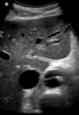
Neonatal Physeal Separation of Distal Humerus During Cesarean Section
Physeal separation of the distal humerus in a newborn is a rare and severe injury that requires immediate treatment. This fracture was reported as an extremely rare complication of cesarean section.1 The correct diagnosis can be established by clinical and radiologic findings. However, this injury can be easily overlooked and misdiagnosed. Presentation often involves swelling, tenderness, and agitation with movement of the elbow.
We report a case in which neonatal physeal separation of the distal humerus occurred during cesarean section. The diagnosis was based on clinical and radiologic/arthrographic findings and treated with closed reduction and percutaneous fixation. The patient’s guardian provided written informed consent for print and electronic publication of this case report.
Case Report
A full-term (40-week gestation) male neonate weighing 3690 g was born through cesarean section at the mother’s request. Apgar score was 9 at 1 minute and 10 at 5 minutes. The vertex position of the fetus was confirmed with preoperative ultrasonography. This was the mother’s first pregnancy and an in vitro fertilization. On his second day of life, the patient was referred to the orthopedic department for evaluation of local swelling and diminished spontaneous motion of the right elbow.
Examination revealed local tenderness and swelling in the anterior and lateral aspects of the elbow. Passive elbow range of motion (ROM) caused agitation, and elbow instability was present. A complete neurovascular examination was performed, and neurovascular injury and compartment syndrome were ruled out. Hematologic workup showed no signs of septic arthritis. Radiographs showed posteromedial displacement of the humeroulnar joint. The patient was placed in a long-arm splint, and no reduction was attempted initially.
The patient was taken to the operating room the same day. With the patient under general anesthesia, an arthrogram of the right elbow was obtained. It showed posteromedial displacement of the distal humeral epiphysis (Figure 1A). Closed reduction was performed, and the quality of the reduction was confirmed by intraoperative imaging. Percutaneously, a single 2-mm Kirschner wire (K-wire) was placed in an oblique fashion from the inferolateral aspect of the distal fragment to the contralateral metaphysis of the humerus (Figure 1B). The patient was put in a long-arm splint with the elbow flexed at 90° and the forearm in midpronation.
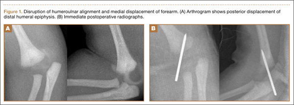
Follow-up visits were scheduled for 1 week, 3 weeks, and 5 weeks after surgery. Three weeks after surgery, callus formation was confirmed, and the K-wire was removed. Five weeks after surgery, the long-arm splint was removed.
At 6-month follow-up, the patient was pain-free and had full elbow ROM, and radiographs (Figures 2A, 2B) confirmed anatomical restoration of the fracture.
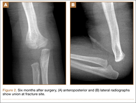
Discussion
Madsen2 reported the incidence of birth-related long-bone fractures, including fractures of the humerus, the femur, and the tibia (< 0.1%). According to that review, only 1 of 105,119 patients sustained traumatic physeal separation of the distal humerus.
Different mechanisms have been described for this rare fracture. As the physeal region is the weakest part of the distal humerus, it is prone to injury by rotational shear forces,3,4 hyperextension of the elbow, or a backward thrust on the forearm with the elbow flexed.5 Excessive traction applied during cesarean delivery might cause physeal separation, which was the possible cause in the present case. Most patients have a complicated birth history.
This injury should be suspected in an irritable newborn with swelling, tenderness, and reduced mobility of the upper extremity. Osteomyelitis and septic arthritis should be considered in the differential diagnosis. Brachial plexus injury and dislocation of the elbow joint should also be kept in mind. Child abuse and metabolic bone diseases (eg, osteogenesis imperfecta) should also be considered.
Anteroposterior and lateral plain radiographs of the elbow usually establish the diagnosis. Alteration of humeroulnar alignment and displacement of the proximal forearm are the key points leading to the diagnosis.
The cartilaginous part of the distal humerus and humeroulnar alignment can be demonstrated by ultrasonography.6 Magnetic resonance imaging (MRI) can be helpful in diagnosis but is seldom required,7 and the sedation or general anesthesia used is a disadvantage. Arthrography is useful not only in diagnosis but in determining the quality of the reduction.8 An arthrogram may show that open reduction is unnecessary.
Treatment differs widely. In neonates, who have a tremendous healing capability, this fracture almost always heals uneventfully. An effective treatment method is closed reduction and cast immobilization. However, valgus malalignment and limited elbow ROM were noted in 5% of the patients treated with this method.4
Jacobsen and colleagues4 reported on 6 neonates who sustained traumatic separation of the distal epiphysis of the humerus at birth and who were treated with casting with or without closed reduction. The authors described good results. One patient had varus malalignment, which was attributed to fragment internal rotation caused by rotational instability.
As our patient’s instability was noted during surgery, we performed percutaneous pinning after arthrography-assisted closed reduction. We considered using 2 lateral pins for fixation, but, after the first pin was placed, fluoroscopic stress testing with the patient under anesthesia demonstrated adequate stability. A second, smaller pin could have been used to control rotation, if needed. Medial pin placement that avoids the ulnar nerve is difficult in the newborn elbow; medial pins should probably be avoided in the newborn, if possible.
Early diagnosis and treatment are essential. Late diagnosis was reported to lead to complications such as varus deformity and restriction of joint ROM.4
Our patient healed without any complications and achieved full ROM. Long-term follow-up is needed to diagnose any physeal bar that might lead to secondary deformities.
Conclusion
Cesarean section is reported to reduce birth complications, but it might cause fractures of the femur and humerus.1 Avoiding application of excessive traction to the forearm can prevent physeal separation of the distal humerus. This entity should be kept in mind as a potential complication of cesarean section. Arthrography is helpful in treatment and may help avoid unnecessary open reduction.
1. Sabat D, Maini L, Gautam VK. Neonatal separation of distal humeral epiphysis during caesarean section: a case report. J Orthop Surg (Hong Kong). 2011;19(3):376-378.
2. Madsen ET. Fractures of the extremities in the newborn. Acta Obstet Gynecol Scand. 1955;34(1):41-74.
3. Peterson HA. Physeal fractures. In: Morrey BF, ed. The Elbow and Its Disorders. Philadelphia, PA: Saunders; 1985:222-236.
4. Jacobsen S, Hansson G, Nathorst-Westfelt J. Traumatic separation of the distal epiphysis of the humerus sustained at birth. J Bone Joint Surg Br. 2009;91(6):797-802.
5. Siffert RS. Displacement of distal humeral epiphysis in the newborn. J Bone Joint Surg Am. 1963;45(1):165-169.
6. Davidson RS, Markowitz RI, Dormans J, Drummond DS. Ultrasonographic evaluation of the elbow in infants and young children after suspected trauma. J Bone Joint Surg Am. 1994;76(12):1804-1813.
7. Sawant MR, Narayanan S, O‘Neill K, Hudson I. Distal humeral epiphysis fracture separation in neonates—diagnosis using MRI scan. Injury. 2002;33(2):179-181.
8. Akbarnia BA, Silberstein MJ, Rende RJ, Graviss ER, Luisiri A. Arthrography in the diagnosis of fractures of the distal end of the humerus in infants. J Bone Joint Surg Am. 1986;68(4):599-602.
Physeal separation of the distal humerus in a newborn is a rare and severe injury that requires immediate treatment. This fracture was reported as an extremely rare complication of cesarean section.1 The correct diagnosis can be established by clinical and radiologic findings. However, this injury can be easily overlooked and misdiagnosed. Presentation often involves swelling, tenderness, and agitation with movement of the elbow.
We report a case in which neonatal physeal separation of the distal humerus occurred during cesarean section. The diagnosis was based on clinical and radiologic/arthrographic findings and treated with closed reduction and percutaneous fixation. The patient’s guardian provided written informed consent for print and electronic publication of this case report.
Case Report
A full-term (40-week gestation) male neonate weighing 3690 g was born through cesarean section at the mother’s request. Apgar score was 9 at 1 minute and 10 at 5 minutes. The vertex position of the fetus was confirmed with preoperative ultrasonography. This was the mother’s first pregnancy and an in vitro fertilization. On his second day of life, the patient was referred to the orthopedic department for evaluation of local swelling and diminished spontaneous motion of the right elbow.
Examination revealed local tenderness and swelling in the anterior and lateral aspects of the elbow. Passive elbow range of motion (ROM) caused agitation, and elbow instability was present. A complete neurovascular examination was performed, and neurovascular injury and compartment syndrome were ruled out. Hematologic workup showed no signs of septic arthritis. Radiographs showed posteromedial displacement of the humeroulnar joint. The patient was placed in a long-arm splint, and no reduction was attempted initially.
The patient was taken to the operating room the same day. With the patient under general anesthesia, an arthrogram of the right elbow was obtained. It showed posteromedial displacement of the distal humeral epiphysis (Figure 1A). Closed reduction was performed, and the quality of the reduction was confirmed by intraoperative imaging. Percutaneously, a single 2-mm Kirschner wire (K-wire) was placed in an oblique fashion from the inferolateral aspect of the distal fragment to the contralateral metaphysis of the humerus (Figure 1B). The patient was put in a long-arm splint with the elbow flexed at 90° and the forearm in midpronation.
Follow-up visits were scheduled for 1 week, 3 weeks, and 5 weeks after surgery. Three weeks after surgery, callus formation was confirmed, and the K-wire was removed. Five weeks after surgery, the long-arm splint was removed.
At 6-month follow-up, the patient was pain-free and had full elbow ROM, and radiographs (Figures 2A, 2B) confirmed anatomical restoration of the fracture.
Discussion
Madsen2 reported the incidence of birth-related long-bone fractures, including fractures of the humerus, the femur, and the tibia (< 0.1%). According to that review, only 1 of 105,119 patients sustained traumatic physeal separation of the distal humerus.
Different mechanisms have been described for this rare fracture. As the physeal region is the weakest part of the distal humerus, it is prone to injury by rotational shear forces,3,4 hyperextension of the elbow, or a backward thrust on the forearm with the elbow flexed.5 Excessive traction applied during cesarean delivery might cause physeal separation, which was the possible cause in the present case. Most patients have a complicated birth history.
This injury should be suspected in an irritable newborn with swelling, tenderness, and reduced mobility of the upper extremity. Osteomyelitis and septic arthritis should be considered in the differential diagnosis. Brachial plexus injury and dislocation of the elbow joint should also be kept in mind. Child abuse and metabolic bone diseases (eg, osteogenesis imperfecta) should also be considered.
Anteroposterior and lateral plain radiographs of the elbow usually establish the diagnosis. Alteration of humeroulnar alignment and displacement of the proximal forearm are the key points leading to the diagnosis.
The cartilaginous part of the distal humerus and humeroulnar alignment can be demonstrated by ultrasonography.6 Magnetic resonance imaging (MRI) can be helpful in diagnosis but is seldom required,7 and the sedation or general anesthesia used is a disadvantage. Arthrography is useful not only in diagnosis but in determining the quality of the reduction.8 An arthrogram may show that open reduction is unnecessary.
Treatment differs widely. In neonates, who have a tremendous healing capability, this fracture almost always heals uneventfully. An effective treatment method is closed reduction and cast immobilization. However, valgus malalignment and limited elbow ROM were noted in 5% of the patients treated with this method.4
Jacobsen and colleagues4 reported on 6 neonates who sustained traumatic separation of the distal epiphysis of the humerus at birth and who were treated with casting with or without closed reduction. The authors described good results. One patient had varus malalignment, which was attributed to fragment internal rotation caused by rotational instability.
As our patient’s instability was noted during surgery, we performed percutaneous pinning after arthrography-assisted closed reduction. We considered using 2 lateral pins for fixation, but, after the first pin was placed, fluoroscopic stress testing with the patient under anesthesia demonstrated adequate stability. A second, smaller pin could have been used to control rotation, if needed. Medial pin placement that avoids the ulnar nerve is difficult in the newborn elbow; medial pins should probably be avoided in the newborn, if possible.
Early diagnosis and treatment are essential. Late diagnosis was reported to lead to complications such as varus deformity and restriction of joint ROM.4
Our patient healed without any complications and achieved full ROM. Long-term follow-up is needed to diagnose any physeal bar that might lead to secondary deformities.
Conclusion
Cesarean section is reported to reduce birth complications, but it might cause fractures of the femur and humerus.1 Avoiding application of excessive traction to the forearm can prevent physeal separation of the distal humerus. This entity should be kept in mind as a potential complication of cesarean section. Arthrography is helpful in treatment and may help avoid unnecessary open reduction.
1. Sabat D, Maini L, Gautam VK. Neonatal separation of distal humeral epiphysis during caesarean section: a case report. J Orthop Surg (Hong Kong). 2011;19(3):376-378.
2. Madsen ET. Fractures of the extremities in the newborn. Acta Obstet Gynecol Scand. 1955;34(1):41-74.
3. Peterson HA. Physeal fractures. In: Morrey BF, ed. The Elbow and Its Disorders. Philadelphia, PA: Saunders; 1985:222-236.
4. Jacobsen S, Hansson G, Nathorst-Westfelt J. Traumatic separation of the distal epiphysis of the humerus sustained at birth. J Bone Joint Surg Br. 2009;91(6):797-802.
5. Siffert RS. Displacement of distal humeral epiphysis in the newborn. J Bone Joint Surg Am. 1963;45(1):165-169.
6. Davidson RS, Markowitz RI, Dormans J, Drummond DS. Ultrasonographic evaluation of the elbow in infants and young children after suspected trauma. J Bone Joint Surg Am. 1994;76(12):1804-1813.
7. Sawant MR, Narayanan S, O‘Neill K, Hudson I. Distal humeral epiphysis fracture separation in neonates—diagnosis using MRI scan. Injury. 2002;33(2):179-181.
8. Akbarnia BA, Silberstein MJ, Rende RJ, Graviss ER, Luisiri A. Arthrography in the diagnosis of fractures of the distal end of the humerus in infants. J Bone Joint Surg Am. 1986;68(4):599-602.
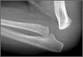
Sacral Insufficiency Fracture After Partial Sacrectomy
Chordomas persist as one of the rarer malignancies, accounting for approximately 1% to 4% of primary bone cancers.1 When chordomas occur, these tumors localize predominantly in the sacrococcygeal region.2 In addition to the urgency for addressing a relatively fast-growing tumor, the anatomical complexity of this area complicates the potential treatments. Furthermore, because of the lack of definitive symptoms, diagnosis is often difficult and typically occurs later in the disease progression.3 An aggressive treatment approach is often warranted because of the biologically aggressive nature of this disease. Full or partial sacrectomy is often the only option that offers the possibility of a long-term cure.4 A sacrectomy is a destructive procedure that can lead to mechanical instability depending on the extent of the surgical resection. When the entire sacrum is removed, there is an obvious need for lumbar-pelvic fixation; however, traditionally, partial sacrectomy procedures have been successfully performed without the need for instrumentation.3,4
This report describes the case of a patient with a noninstrumented sacrectomy procedure distal to the S2 foramen that resulted in an insufficiency fracture. The patient provided written informed consent for print and electronic publication of this case report.
Case Report
A 66-year-old woman presented with severe lower back pain of a month’s duration. Her pain was localized to the coccyx area and did not radiate to the lower legs. Although the pain could not be elicited by palpation, pain occurred when sitting and increased when standing for prolonged periods. Three weeks prior to the patient’s initial office visit, she noticed transient constipation and urinary retention. She denied any fever, chills, nausea, vomiting, unexplained weight loss, weight gain, and abdominal pain. There were no motor deficits in the lower limbs. Sensation was intact in the lower limbs except for the posterior aspect of the left leg down to the popliteal fossa, where light touch perception was absent. She recalled the loss of sensation in this area 20 years earlier, and it had neither progressed nor abated since then. She had a history of osteoarthritis and had been diagnosed with degenerative disc disease 20 years ago.
A radiographic review of her lumbar spine showed significant spinal stenosis and degenerative disease of the lumbar spine on non–contrast-enhanced magnetic resonance imaging (MRI). The MRI also revealed a large, soft-tissue mass at the S3-S4 level, eroding most of the S3 vertebral body and extending into the S4 vertebral body. The MRI images used for this analysis were insufficient in providing a complete portrayal of the entire mass. Because of these uncertainties, contrast-enhanced and non–contrast-enhanced pelvic MRIs were taken. The MRI analyses identified a mass density replacing the lower sacrum and upper coccyx that was bright in intensity on T2 and dim on T1 sequences. Sagittal imaging measurements were 5.9×2.5 cm and 4.4 cm right-to-left on coronal imaging. The mass extended beyond the involved sacrococcygeal segments and dorsally beyond the normal cortical margin of the sacrum and coccyx (Figures 1A, 1B). Next, a computer tomographic–guided needle biopsy through a posterior paraspinal approach was obtained. The biopsy consisted of fragments of a malignant neoplasm consistent with physaliferous cells. The specimen was positive for pankeratin, keratin AE1/AE3, epithelial membrane antigen, and S100 protein. This supported a diagnosis of a sacral chordoma. An en bloc sacrectomy at S2; lumbar laminectomy at L5, S1, and S2; and thecal sac transection at the S3 nerve roots were planned.
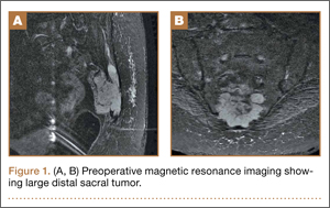
Surgical Procedure
The patient was placed in the prone position after a colostomy and harvesting of a rectus flap in the supine position. A midline incision was made from the spinous process of L5 down through the tip of the coccyx, and soft tissues were elevated while maintaining hemostasis. The most distal part of the coccyx was transected, and using a combination of electrocautery and paraspinal elevators, rectal and peritoneal tissues were elevated off the ventral component of the coccyx until a hand could easily reach the bifurcation of the iliac vessels. Electrocautery transected paraspinal muscles at the S1 and S2 levels while the more cranial paraspinal musculature was elevated to allow for a laminectomy. The spinous processes were removed from L5 and the sacrum with a Leksell rongeur. A high-speed burr thinned the dorsal lamina components of L5, S1, and the leading edge of S2. The L5, S1, and S2 nerve roots were identified. The gluteal muscles were elevated and the sacral coccygeal ligaments were transected. After identifying the sciatic notches, the S2 nerves exiting the foramen were identified, followed out through the sciatic notch, and a wire was passed through this region. Three 2-0 silk ties were applied to the exposed portion of the S3 and S4 nerve roots, and the nerves were transected because they were integrally involved with the tumor. Using a series of high-speed burrs and osteotomes, lateral cuts were made through the sciatic notch. The sacrum was osteotomized at the S2 sacral foramen through the anterior component with an osteotome, while a hand protected the ventral structures. The remaining parts of the S3 and S4 dorsal nerve roots were transected. An incision through the peritoneum was made to access the rectus flap, and a plastic surgeon closed the wounds and secured the flap.
Postoperative Course
The patient’s final pathology confirmed a chordoma with negative margins. Postoperatively, the rectus flap became ischemic and a wound infection developed. It was irrigated, débrided, and treated with vacuum-assisted closure (VAC), in addition to perioperative antibiotic administration. An abdominal computed tomography (CT) scan did not show any fistula, and her wound remained healthy, pink, and viable as her VAC was changed every 3 days. Because the patient’s nutritional status was compromised, she started nutritional supplements in addition to a regular diet. Physical therapy was prescribed and the patient began bladder training with self-catheterization after a failed voiding trial attempt. After 2 months of convalescence, the patient had mobilized well and had progressed to walking without an ambulatory aide.
At her third postoperative month, the patient noted new onset of extreme pain in the groin and left thigh regions. The patient was examined and appeared to have a stable neurological exam. She had reproducible pain with a FABER (Flexion, Abduction, External Rotation, and Extension) test. MRI showed increased signal on short tau inversion recovery (STIR) sequences and T2-weighted images that was consistent with a left sacral ala stress fracture with a vertically oriented fracture line (Figures 2A, 2B). The patient was asked to begin utilizing a walker for ambulatory assistance, but her weight-bearing status was not changed. Over the course of 3 months, the patient noted a resolution of her pain. All postoperative MRI images confirmed the patient to be disease-free; and in addition, all of her follow-up radiographs showed a stable pelvic ring (Figures 3A, 3B). At her 2-year follow-up, the patient remained disease- and pain-free.
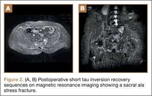
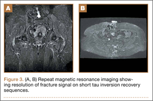
Discussion
Full discussions of the mechanical considerations of a partial sacrectomy have been described previously5-8; however, surgeons typically consider the need for lumbar-pelvic stabilization when the surgical resection requires a violation of the S1 body. Approximately two-thirds of sacral tumors occur at or below the level of the S2 body.8 These lesions of the caudal sacrum can sometimes be effectively resected with transverse partial sacrectomy. Great care is taken to resect only the portion of the sacrum necessary for local disease control, sparing as much of the sacroiliac joint and as many of the lumbosacral nerve roots as possible.
Under normal conditions, the sacroiliac articulation is stabilized by both its geometric interface and its extraordinarily strong ligaments. This spatial arrangement conveys stability primarily against caudal migration of the sacrum. The sacroiliac, sacrotuberous, sacrospinous, and lumbosacral ligaments, which are among the strongest ligaments in the body, primarily act to provide stability to the pelvic ring by preventing diastasis. The combination of these factors renders the spinopelvic segment especially stable. Previously, 2 biomechanical studies that specifically looked at extreme loading patterns to better understand the need for lumbar-pelvic instrumentation predicted a fracture pattern when there was an inability of the base of the sacral ala to resist shear.8,9 This is precisely where our patient’s insufficiency fracture occurred.
To our knowledge, this is the first reported in vivo evidence of this fracture pattern. While this patient’s potential history of osteoporosis may have elevated or contributed to her risk for fracture, her preoperative bone densitometry, with T scores of -1.0 on the left and right femur necks and 0.8 on her L1-L4 anteroposterior spine, would argue against this risk factor. None of these values represent a truly osteoporotic patient. It would appear that our patient sustained the fracture pattern predicted by Hugate and colleagues.8
The edema seen on the MRI most likely represents a fracture; however, sacroiliitis and infection are also potential diagnoses. Because there was no tumor in this region on the preoperative scans, we thought that a residual tumor was unlikely. The signal changes seen on T2 MRI sequences represent edema. The use of a bone scan that detects healing bone may have been a useful additional study to confirm this fracture as opposed to sacroiliitis. A CT scan would have been a potentially useful study to provide detail of fracture displacement and the overall fracture pattern. Standing plain radiographs are best for viewing fracture displacement with weight-bearing.
Surgeons contemplating performing partial sacrectomies should bear in mind that, even with preservation of the S1 body, a potential for fracture exists as evidenced by our patient. In our opinion, this patient did not require instrumentation but a more gradual rehabilitation program.
1. Varga PP, Lazary A. Chordoma of the sacrum: “en bloc” total sacrectomy and lumbopelvic reconstruction. Eur Spine. 2010;19(6):1039-1040.
2. Heffelfinger MJ, Dahlin DC, MacCarty CS, Beabout JW. Chordomas and cartilaginous tumors at the skull base. Cancer. 1973; 32(2):410-420.
3. Varga PP, Bors I, Lazary A. Sacral tumors and management. Orthop Clin North Am. 2009;40(1):105-123.
4. Puri A, Agarwal MG, Shah M, et al. Decision making in primary sacral tumors. Spine J. 2009;9(5):396-403.
5. Cheng L, Yu Y, Zhu R, et al. Structural stability of different reconstruction techniques following total sacrectomy: a biomechanical study. Clin Biomech (Bristol, Avon). 2011;26 (10):977-981.
6. Yu BS, Zhuang XM, Li ZM, et al. Biomechanical effects of the extent of sacrectomy on the stability of lumbo-iliac reconstruction using iliac screw techniques: What level of sacrectomy requires the bilateral dual iliac screw technique? Clin Biomech (Bristol, Avon). 2010;25(9):867-872.
7. Yu B, Zheng Z, Zhuang X, et al. Biomechanical effects of transverse partial sacrectomy on the sacroiliac joints: an in vitro human cadaveric investigation of the borderline of sacroiliac joint instability. Spine (Phila Pa 1976). 2009;34(13):1370-1375.
8. Hugate RR Jr, Dickey ID, Phimolsarnti R, Yaszemski MJ, Sim FH. Mechanical effects of partial sacrectomy: when is reconstruction necessary? Clin Orthop. 2006;450:82-88.
9. Gunterberg B, Romanus B, Stener B. Pelvic strength after major amputation of the sacrum. An experimental study. Acta Orthop Scand. 1976; 47(6):635-642.
Chordomas persist as one of the rarer malignancies, accounting for approximately 1% to 4% of primary bone cancers.1 When chordomas occur, these tumors localize predominantly in the sacrococcygeal region.2 In addition to the urgency for addressing a relatively fast-growing tumor, the anatomical complexity of this area complicates the potential treatments. Furthermore, because of the lack of definitive symptoms, diagnosis is often difficult and typically occurs later in the disease progression.3 An aggressive treatment approach is often warranted because of the biologically aggressive nature of this disease. Full or partial sacrectomy is often the only option that offers the possibility of a long-term cure.4 A sacrectomy is a destructive procedure that can lead to mechanical instability depending on the extent of the surgical resection. When the entire sacrum is removed, there is an obvious need for lumbar-pelvic fixation; however, traditionally, partial sacrectomy procedures have been successfully performed without the need for instrumentation.3,4
This report describes the case of a patient with a noninstrumented sacrectomy procedure distal to the S2 foramen that resulted in an insufficiency fracture. The patient provided written informed consent for print and electronic publication of this case report.
Case Report
A 66-year-old woman presented with severe lower back pain of a month’s duration. Her pain was localized to the coccyx area and did not radiate to the lower legs. Although the pain could not be elicited by palpation, pain occurred when sitting and increased when standing for prolonged periods. Three weeks prior to the patient’s initial office visit, she noticed transient constipation and urinary retention. She denied any fever, chills, nausea, vomiting, unexplained weight loss, weight gain, and abdominal pain. There were no motor deficits in the lower limbs. Sensation was intact in the lower limbs except for the posterior aspect of the left leg down to the popliteal fossa, where light touch perception was absent. She recalled the loss of sensation in this area 20 years earlier, and it had neither progressed nor abated since then. She had a history of osteoarthritis and had been diagnosed with degenerative disc disease 20 years ago.
A radiographic review of her lumbar spine showed significant spinal stenosis and degenerative disease of the lumbar spine on non–contrast-enhanced magnetic resonance imaging (MRI). The MRI also revealed a large, soft-tissue mass at the S3-S4 level, eroding most of the S3 vertebral body and extending into the S4 vertebral body. The MRI images used for this analysis were insufficient in providing a complete portrayal of the entire mass. Because of these uncertainties, contrast-enhanced and non–contrast-enhanced pelvic MRIs were taken. The MRI analyses identified a mass density replacing the lower sacrum and upper coccyx that was bright in intensity on T2 and dim on T1 sequences. Sagittal imaging measurements were 5.9×2.5 cm and 4.4 cm right-to-left on coronal imaging. The mass extended beyond the involved sacrococcygeal segments and dorsally beyond the normal cortical margin of the sacrum and coccyx (Figures 1A, 1B). Next, a computer tomographic–guided needle biopsy through a posterior paraspinal approach was obtained. The biopsy consisted of fragments of a malignant neoplasm consistent with physaliferous cells. The specimen was positive for pankeratin, keratin AE1/AE3, epithelial membrane antigen, and S100 protein. This supported a diagnosis of a sacral chordoma. An en bloc sacrectomy at S2; lumbar laminectomy at L5, S1, and S2; and thecal sac transection at the S3 nerve roots were planned.
Surgical Procedure
The patient was placed in the prone position after a colostomy and harvesting of a rectus flap in the supine position. A midline incision was made from the spinous process of L5 down through the tip of the coccyx, and soft tissues were elevated while maintaining hemostasis. The most distal part of the coccyx was transected, and using a combination of electrocautery and paraspinal elevators, rectal and peritoneal tissues were elevated off the ventral component of the coccyx until a hand could easily reach the bifurcation of the iliac vessels. Electrocautery transected paraspinal muscles at the S1 and S2 levels while the more cranial paraspinal musculature was elevated to allow for a laminectomy. The spinous processes were removed from L5 and the sacrum with a Leksell rongeur. A high-speed burr thinned the dorsal lamina components of L5, S1, and the leading edge of S2. The L5, S1, and S2 nerve roots were identified. The gluteal muscles were elevated and the sacral coccygeal ligaments were transected. After identifying the sciatic notches, the S2 nerves exiting the foramen were identified, followed out through the sciatic notch, and a wire was passed through this region. Three 2-0 silk ties were applied to the exposed portion of the S3 and S4 nerve roots, and the nerves were transected because they were integrally involved with the tumor. Using a series of high-speed burrs and osteotomes, lateral cuts were made through the sciatic notch. The sacrum was osteotomized at the S2 sacral foramen through the anterior component with an osteotome, while a hand protected the ventral structures. The remaining parts of the S3 and S4 dorsal nerve roots were transected. An incision through the peritoneum was made to access the rectus flap, and a plastic surgeon closed the wounds and secured the flap.
Postoperative Course
The patient’s final pathology confirmed a chordoma with negative margins. Postoperatively, the rectus flap became ischemic and a wound infection developed. It was irrigated, débrided, and treated with vacuum-assisted closure (VAC), in addition to perioperative antibiotic administration. An abdominal computed tomography (CT) scan did not show any fistula, and her wound remained healthy, pink, and viable as her VAC was changed every 3 days. Because the patient’s nutritional status was compromised, she started nutritional supplements in addition to a regular diet. Physical therapy was prescribed and the patient began bladder training with self-catheterization after a failed voiding trial attempt. After 2 months of convalescence, the patient had mobilized well and had progressed to walking without an ambulatory aide.
At her third postoperative month, the patient noted new onset of extreme pain in the groin and left thigh regions. The patient was examined and appeared to have a stable neurological exam. She had reproducible pain with a FABER (Flexion, Abduction, External Rotation, and Extension) test. MRI showed increased signal on short tau inversion recovery (STIR) sequences and T2-weighted images that was consistent with a left sacral ala stress fracture with a vertically oriented fracture line (Figures 2A, 2B). The patient was asked to begin utilizing a walker for ambulatory assistance, but her weight-bearing status was not changed. Over the course of 3 months, the patient noted a resolution of her pain. All postoperative MRI images confirmed the patient to be disease-free; and in addition, all of her follow-up radiographs showed a stable pelvic ring (Figures 3A, 3B). At her 2-year follow-up, the patient remained disease- and pain-free.
Discussion
Full discussions of the mechanical considerations of a partial sacrectomy have been described previously5-8; however, surgeons typically consider the need for lumbar-pelvic stabilization when the surgical resection requires a violation of the S1 body. Approximately two-thirds of sacral tumors occur at or below the level of the S2 body.8 These lesions of the caudal sacrum can sometimes be effectively resected with transverse partial sacrectomy. Great care is taken to resect only the portion of the sacrum necessary for local disease control, sparing as much of the sacroiliac joint and as many of the lumbosacral nerve roots as possible.
Under normal conditions, the sacroiliac articulation is stabilized by both its geometric interface and its extraordinarily strong ligaments. This spatial arrangement conveys stability primarily against caudal migration of the sacrum. The sacroiliac, sacrotuberous, sacrospinous, and lumbosacral ligaments, which are among the strongest ligaments in the body, primarily act to provide stability to the pelvic ring by preventing diastasis. The combination of these factors renders the spinopelvic segment especially stable. Previously, 2 biomechanical studies that specifically looked at extreme loading patterns to better understand the need for lumbar-pelvic instrumentation predicted a fracture pattern when there was an inability of the base of the sacral ala to resist shear.8,9 This is precisely where our patient’s insufficiency fracture occurred.
To our knowledge, this is the first reported in vivo evidence of this fracture pattern. While this patient’s potential history of osteoporosis may have elevated or contributed to her risk for fracture, her preoperative bone densitometry, with T scores of -1.0 on the left and right femur necks and 0.8 on her L1-L4 anteroposterior spine, would argue against this risk factor. None of these values represent a truly osteoporotic patient. It would appear that our patient sustained the fracture pattern predicted by Hugate and colleagues.8
The edema seen on the MRI most likely represents a fracture; however, sacroiliitis and infection are also potential diagnoses. Because there was no tumor in this region on the preoperative scans, we thought that a residual tumor was unlikely. The signal changes seen on T2 MRI sequences represent edema. The use of a bone scan that detects healing bone may have been a useful additional study to confirm this fracture as opposed to sacroiliitis. A CT scan would have been a potentially useful study to provide detail of fracture displacement and the overall fracture pattern. Standing plain radiographs are best for viewing fracture displacement with weight-bearing.
Surgeons contemplating performing partial sacrectomies should bear in mind that, even with preservation of the S1 body, a potential for fracture exists as evidenced by our patient. In our opinion, this patient did not require instrumentation but a more gradual rehabilitation program.
1. Varga PP, Lazary A. Chordoma of the sacrum: “en bloc” total sacrectomy and lumbopelvic reconstruction. Eur Spine. 2010;19(6):1039-1040.
2. Heffelfinger MJ, Dahlin DC, MacCarty CS, Beabout JW. Chordomas and cartilaginous tumors at the skull base. Cancer. 1973; 32(2):410-420.
3. Varga PP, Bors I, Lazary A. Sacral tumors and management. Orthop Clin North Am. 2009;40(1):105-123.
4. Puri A, Agarwal MG, Shah M, et al. Decision making in primary sacral tumors. Spine J. 2009;9(5):396-403.
5. Cheng L, Yu Y, Zhu R, et al. Structural stability of different reconstruction techniques following total sacrectomy: a biomechanical study. Clin Biomech (Bristol, Avon). 2011;26 (10):977-981.
6. Yu BS, Zhuang XM, Li ZM, et al. Biomechanical effects of the extent of sacrectomy on the stability of lumbo-iliac reconstruction using iliac screw techniques: What level of sacrectomy requires the bilateral dual iliac screw technique? Clin Biomech (Bristol, Avon). 2010;25(9):867-872.
7. Yu B, Zheng Z, Zhuang X, et al. Biomechanical effects of transverse partial sacrectomy on the sacroiliac joints: an in vitro human cadaveric investigation of the borderline of sacroiliac joint instability. Spine (Phila Pa 1976). 2009;34(13):1370-1375.
8. Hugate RR Jr, Dickey ID, Phimolsarnti R, Yaszemski MJ, Sim FH. Mechanical effects of partial sacrectomy: when is reconstruction necessary? Clin Orthop. 2006;450:82-88.
9. Gunterberg B, Romanus B, Stener B. Pelvic strength after major amputation of the sacrum. An experimental study. Acta Orthop Scand. 1976; 47(6):635-642.
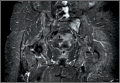
The Role of Computed Tomography for Postoperative Evaluation of Percutaneous Sacroiliac Screw Fixation and Description of a “Safe Zone”
Pelvic injuries account for 3% of all skeletal fractures.1 Injury to the sacroiliac (SI) joint is frequently associated with unstable pelvic ring fractures, which are potentially life-threatening injuries. Surgical fixation of these injuries is preferred to nonoperative treatment given the potential for improved reduction and early mobilization and weight-bearing, thereby decreasing perioperative morbidity and improving functional outcome.2
The classic method of surgical fixation of the SI joint consisted of open reduction and internal fixation. This method carried a substantial risk for large dissection, iatrogenic nerve injury, and increased blood loss to the already traumatized patient.3 Percutaneous fixation allows for a shorter operating time, decreased soft-tissue stripping, and decreased blood loss compared with a traditional open procedure.4 However, posterior pelvic anatomy is complex and variable, and reports have found screw misplacements as high as 24%5 and neurologic complication rates up to 18%.6-9
Various imaging modalities, including fluoroscopy,5 computed tomography (CT),6-7 fluoroscopic CT, and computer-assisted techniques5,9 have been used to achieve proper screw placement. Conventional fluoroscopy is the standard for intraoperative screw placement. However, acceptable reduction of the SI joint and proper implantation of the screws without perforation of the neural foramina is challenging, especially when coupled with difficulties of fluoroscopic imaging and variations in pelvic anatomy.
Sacral dysplasia has been reported to occur in up to 20% to 40% of the population and has significant implications in patients indicated for iliosacral screw placement.10 Incorrect placement of iliosacral screws may result in iatrogenic neurovascular complications.11-13 Malpositioned screws using fluoroscopic guidance have been reported in 2% to 15% of patients with an incidence of neurologic compromise between 0.5% and 7.7%. As little as 4° of misdirection can result in damage to neurovascular structures.14
At our institution, we routinely obtained postoperative CT to evaluate the placement of SI screws. The objective of this retrospective study is to evaluate the rate of revision surgery of percutaneous SI screw fixation, to determine whether CT is an accurate tool for evaluation of the reduction and the need for revision surgery, and to decide if any violation of the neural foramina is safe.
Materials and Methods
After institutional review board approval, we retrospectively reviewed and evaluated medical records and radiographs of all patients who sustained unstable pelvic ring fractures between July 1, 2005, and June 30, 2010. We identified all patients who were treated with closed reductions and percutaneous iliosacral screw fixation, according to the method described by Routt in 1995.4 We excluded all pelvic fractures in patients who underwent open reduction for the posterior injury or did not have percutaneous SI screws placed, those with spinal injury, and those without follow-up. Of the 46 patients who met the inclusion criteria were 26 men and 20 women with a mean age of 42 years (range, 16 to 73 years). Motor vehicle accidents accounted for 13 cases; 19 were crush injuries and 14 were falls from height. Seventeen patients (37%) met the radiographic criteria for sacral dysmorphism. Forty-two of the 46 patients were polytrauma patients with associated musculoskeletal injuries and/or abdominal, chest, or head injuries.
Six patients presented with some neurologic deficit at the time of injury; all fractures were closed. The initial imaging study included plain anteroposterior (AP), inlet, and outlet radiographs of the pelvis and a pelvic CT scan. Using the classification of Young and Burgess,15 there were 3 vertical shear injuries, 13 lateral compression–type injuries, 17 anterior-posterior–type injuries, 7 sacral fractures, and 6 combination- or unclassifiable-type pelvic injuries. Of the sacral fractures, there were 3 Denis zone 1, 3 Denis zone 2, and 1 Denis zone 3.
The pelvic CT scan included the entire pelvis from the ilium to the ischial tuberosities. Each scan consisted of either a 5.0-mm or a 2.5-mm sequential axial image. A picture archiving and communication system (PACS) workstation using Centricity version 2.1 (GE Medical Systems, Waukesha, Wisconsin) was used to analyze each scan with a bone algorithm. On PACS, each initial displacement was characterized by the amount of SI joint widening at the level of the S1 and was measured using digital calipers.
Surgery
Mean time to surgery was 4 days (range, 2 to 15 days) after the injury. A total of 51 SI screws were implanted in 46 patients. We achieved closed reduction of the posterior pelvic ring by various techniques, including compression with percutaneous partially threaded screw fixation. In the cases in which the posterior ring lesion was associated with a pure pubic symphysis disruption, the anterior pelvis was initially reduced and stabilized with small-fragment plate fixation (Synthes, Inc, Paoli, Pennsylvania). The posterior complex was stabilized with 1 screw in 41 patients, 2 cases required a transiliac screw, and 2 screws (S1 and S2) were placed in each of the remaining 3 cases. Definitive stabilization of the posterior pelvis was achieved with percutaneous, partially threaded 7.3- or 7.5-mm–diameter cannulated screws (Synthes, Inc, and Zimmer Inc, Warsaw, Indiana, respectively) in 42 fractures and 6.5-mm screws (Synthes, Inc) in 4 fractures. In 11 cases where the fracture was through the sacrum, fully threaded cannulated screws were used to avoid compression. Screw insertion was performed under fluoroscopic guidance with inlet, outlet, and lateral sacral views. One of 2 fellowship-trained trauma surgeons performed the surgeries. Rehabilitation plans were customized to each patient based on concomitant injuries.
Postoperative Assessment
AP, lateral sacral, and inlet and outlet postoperative radiographs were taken in all cases within 24 hours after surgery. Pelvic CT was also obtained within 24 hours of surgery to review reduction and screw placement.
Using the measurement tool on the PACS system, we measured the penetration of the screw into the foramen. Screws were graded as intraosseous (completely contained within the sacral bone), skived (less than 2 mm of partial penetration into the S1 foramen), or extruded (the screw not contained by the bone). Screw penetration of the S1 was evaluated on the radiographic images as well as the axial images of the CT scans.
After surgery, the senior orthopedic resident and attending surgeon performed and documented detailed neurologic evaluations. They reviewed the medical record for neurologic deficit following surgical fixation.
Results
The mean follow-up time was 12 months (range, 8 months to 2 years). Two patients expired secondary to associated injuries. There were no early deaths related to the pelvic surgery. Stable fixation, including bone or ligamentous healing, as well as full weight-bearing status, was noted in every case. No case exhibited loss of reduction or implant failure or infection.
According to Matta’s criteria of anatomic reduction within 1 cm, all patients were found to have satisfactory reductions.7 Six of 46 patients had documented preoperative neurologic deficits. After percutaneous screw fixation, 10 of 46 patients had postoperative neurologic deficit, 2 of which were unchanged from preoperative evaluation. Of the 8 patients with new/altered postoperative neurologic deficit, CT showed neural foramen penetration greater than 2.1 mm in only 2 patients. Both patients underwent screw revision, resulting in improved neurologic deficit. The remaining 4 patients did not have foramen penetration and improved their neurologic function over the course of 2 weeks with return to presurgical status by 6 weeks without necessitating screw removal.
Twenty-three of the 51 screws (45%) had some violation of the S1 foramen on the CT. There were 17 patients with dysmorphic sacrums in which 21 S1 screws were placed. Eleven of 21 (52%) screws showed some penetration of the S1 foramen on CT. There were 29 patients with normal sacral morphology in which 30 S1 screws were placed. Twelve of 30 (40%) screws penetrated the S1 foramen. All violations were in the superior one-third position of the foramen. Two of 46 (4%; 1 with dysmorphism, 1 without) had a new neurologic deficit associated with the surgery (Table). CT showed sacral foramen penetration, and both screws were revised with a better neurologic examination.
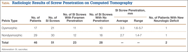
High-resolution CTs were obtained in 32 patients, while 14 patients underwent the standard 5.0-mm–cut CTs. Of the 32 patients in which a 2.5-mm high-resolution CT was obtained, 20 (62.5%) had evidence of screw penetration (Figures 1, 2). All violations of the S1 neural foramen were in the superior portion of the foramen.
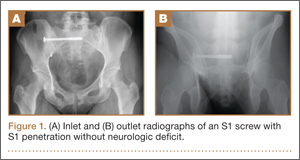
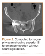
When compared with patients who had a 5.0-mm CT, the patients who underwent a high-resolution CT were more likely to show neural foramen penetration (P = .3). The average screw penetration into the S1 neural foramen measured 3.3 mm (range, 1.6-5.7 mm) in dysmorphic sacrum and 2.7 mm (range, 1.4-7 mm) in normal sacrum. However, in our study, any foramen penetration of less than 2.1 mm on CT did not result in neurologic deficit.
Discussion
Pelvic fractures are fairly common and represent approximately 5% of all trauma admissions and 3% of all skeletal fractures nationwide.1 The current treatment for SI disruption is either nonoperative or operative. Surgical fixation is technically demanding and surgeons often need a long learning curve to acquire the demanding technique because of the limitations of radiographic visualization of the relevant landmarks.16
Letournel17 developed the technique for iliosacral screw fixation for the treatment of posterior pelvic ring injuries, where 1 or 2 large screws (6.5-7.3 mm in diameter) are inserted under fluoroscopic guidance through the ilium, across the SI articulation, and into the superior sacral vertebral bodies using percutaneous techniques. Currently, the standard procedure to accomplish the percutaneous placement of iliosacral screws derives mainly from the technique described by Matta with the C-arm fluoroscopy visualizing the pelvis in 3 views: strict AP, inlet, and outlet views.7
Routt and colleagues4 recommend a strict lateral view of the sacrum, particularly when crossing the narrow zone of the sacral alar. They reported high union rates and accurate placement of the screws.4 There are limitations to the use of biplanar fluoroscopy because the intraoperative images are not orthogonal, with the average arc (67º) between the ideal inlet and outlet. However, because of the variability in sacral anatomy, CT guidance was recommended by others.2,6,8,18 Operating in a CT suite had other complications. Misinterpretation of CT led to “in-out-in” screws, which resulted in neurapraxia.
In our study, we used the technique described by Matta and colleagues for placement of the screws and performed a postoperative CT to evaluate screw placement and to assess pelvic reduction.7 We had a high penetration rate using CT, which increased with better resolution, even though none of the radiographs showed any obvious evidence of misplacement of the screws. Ebraheim and colleagues6 described the relationship of the S1 nerve root in its neural foramen and found it to be approximately 8.7 mm inferior and 7.8 mm medial to the starting point for a pedicle screw. Given these numbers, it is possible that a large amount of skiving can be tolerated contingent on an adequate reduction of the SI joint.
Because of our high rates of skiving and low rates of neurologic deficit, a new “safe zone” for screw insertion can be expanded to include skiving of the S1 neural foramen up to 3 mm without fear of nerve root injury. However, drilling and screw insertion at higher speeds can also cause neurologic injury secondary to thermal injury or soft tissue being caught up in a rotating drill/screw.
Evaluation of placement of percutaneous SI screw placement in our study resulted in neural foramen penetration in 43% of SI screws, which is higher than other studies.14,19,20 Our study showed that screw penetration up to 2 mm does not correlate with neurologic deficit. Iatrogenic neurologic deficit secondary to perforation of the foramina occurred in only 1 patient. Penetration of the foramina in all cases was in the superior portion of the foramen. We propose that there is a safe zone within the S1 neural foramen, and small amounts of penetration in the superior one-third of the foramen on axial CT images do not correlate with neurologic deficit. This potential safe zone is predicated on adequate reduction of the SI joint.
Neural foramen penetration shown on postoperative CT does not necessarily correlate with neurologic deficit. A postoperative CT is not indicated unless there are findings of a postoperative nerve injury. Our ideal screw placement skives the superior S1 foramen allowing for a larger screw diameter in a safe zone.
CT-guided placement has been proposed; however, concerns about radiation exposure, cost, and feasibility with similar outcomes compared with fluoroscopic-guided screw placement has resulted in its falling out of favor.
Iatrogenic nerve injuries are reported to occur in 0% to 6% of all percutaneous SI screw placement.14,21 Risk factors for iatrogenic nerve injury while using fluoroscopic guidance include sacral morphologic abnormalities, presence of intestinal gas, or contrast.22 Although these may be minimized with proper use of fluoroscopy, obtaining anatomic reduction as well as a thorough understanding of the pelvic morphology, the surgeon must be prepared to obtain further studies, such as a CT scan, if there is postoperative neurologic deficit.
Based on our findings, we do not routinely obtain a postoperative CT for SI screw placement, unless there is concern for malreduction or there is neurologic deficit. We also believe that up to 2 mm of foramen penetration is safe and does not result in neurologic deficit.
1. Failinger MS, McGanity PL. Unstable fractures of the pelvic ring. J Bone and Joint Surg Am. 1992;74(5):781-791.
2. Smith HE, Yuan PS, Sasso R, Papadopolous S, Vaccaro AR. An evaluation of image-guided technologies in the placement of percutaneous iliosacral screws. Spine (Phila Pa 1976). 2006;31(2):234-238.
3. Judet R, Judet J, Letournel E. Fractures of the acetabulum: classification and surgical approaches for open reduction. Preliminary report. J Bone Joint Surg Am. 1964;46(16):1615-1646.
4. Routt ML Jr, Kregor PJ, Simonian PT, Mayo KA. Early results of percutaneous iliosacral screws placed with the patient in the supine position. J Orthop Trauma. 1995;9(3):207-214.
5. Tonetti J, Carrat L, Blendea S, et al. Clinical results of percutaneous pelvic surgery. Computer assisted surgery using ultrasound compared to standard fluoroscopy. Comput Aided Surg. 2001;6(4):204-211.
6. Ebraheim NA, Coombs R, Jackson WT, Rusin JJ. Percutaneous computed tomography-guided stabilization of posterior pelvic fractures. Clin Orthop. 1994;(307):222-228.
7. Keating JF, Werier J, Blachut P, et al. Early fixation of the vertically unstable pelvis: the role of iliosacral screw fixation of the posterior lesion. J Orthop Trauma. 1999;13(2):107-113.
8. Webb LX, de Araujo W, Donofrio P, et al. Electromyography monitoring for percutaneous placement of iliosacral screws. J Orthop Trauma. 2000;14(4):245-254.
9. Barrick EF, O’Mara JW, Lane HE 3rd. Iliosacral screw insertion using computer-assisted CT image guidance: a laboratory study. Comput Aided Surg. 1998;3(6):289-296.
10. Routt ML Jr, Simonian PT, Agnew SG, Mann FA. Radiographic recognition of the sacral alar slope for optimal placement of iliosacral screws: a cadaveric and clinical study. J Orthop Trauma. 1996;10(3):171-177.
11. Altman DT, Jones CB, Routt ML Jr. Superior gluteal artery injury during iliosacral screw placement. J Orthop Trauma. 1999;13(3):220-227.
12. Stephen DJ. Pseudoaneurysm of the superior gluteal arterial system: an unusual cause of pain after a pelvic fracture. J Trauma. 1997;43(1):146-149.
13. Stöckle U, König B, Hofstetter R, Nolte LP, Haas NP. [Navigation assisted by image conversion. An experimental study on pelvic screw fixation]
[in German]. Unfallchirurg. 2001;104(3):215-220.
14. Templeman D, Schmidt A, Freese J, Weisman I, et al. Proximity of iliosacral screws to neurovascular structures after internal fixation. Clin Orthop. 1996;(329):194-198.
15. Young JW, Burgess AR, Brumback RJ, Poka A. Pelvic fractures: value of plain radiography in early assessment and management. Radiology. 1986;160(2):445-451.
16. Graves ML, Routt ML Jr. Iliosacral screw placement: are uniplanar changes realistic based on standard fluoroscopic imaging? J Trauma. 2011;7(1):204-208.
17. Letournel E. Pelvic fractures. Injury. 1978;10(2):145-148.
18. Blake-Toker AM, Hawkins L, Nadalo L, et al. CT guided percutaneous fixation of sacroiliac fractures in trauma patients. J Trauma. 2001;51(6):1117-1121.
19. Hinsche AF, Giannoudis PV, Smith RM. Fluoroscopy-based multiplanar image guidance for insertion of sacroiliac screws. Clin Orthop. 2002;(395):135-144.
20. van den Bosch EW, van Zwienen CM, van Vugt AB. Fluoroscopic positioning of sacroiliac screws in 88 patients. J Trauma. 2002;53(1):44-48.
21. Cole JD, Blum DA, Ansel LJ. Outcome after fixation of unstable posterior pelvic ring injuries. Clin Orthop. 1996;(329):160-179.
22. Routt ML Jr, Simonian PT. Closed reduction and percutaneous skeletal fixation of sacral fractures. Clin Orthop. 1996;(329):121-128.
Pelvic injuries account for 3% of all skeletal fractures.1 Injury to the sacroiliac (SI) joint is frequently associated with unstable pelvic ring fractures, which are potentially life-threatening injuries. Surgical fixation of these injuries is preferred to nonoperative treatment given the potential for improved reduction and early mobilization and weight-bearing, thereby decreasing perioperative morbidity and improving functional outcome.2
The classic method of surgical fixation of the SI joint consisted of open reduction and internal fixation. This method carried a substantial risk for large dissection, iatrogenic nerve injury, and increased blood loss to the already traumatized patient.3 Percutaneous fixation allows for a shorter operating time, decreased soft-tissue stripping, and decreased blood loss compared with a traditional open procedure.4 However, posterior pelvic anatomy is complex and variable, and reports have found screw misplacements as high as 24%5 and neurologic complication rates up to 18%.6-9
Various imaging modalities, including fluoroscopy,5 computed tomography (CT),6-7 fluoroscopic CT, and computer-assisted techniques5,9 have been used to achieve proper screw placement. Conventional fluoroscopy is the standard for intraoperative screw placement. However, acceptable reduction of the SI joint and proper implantation of the screws without perforation of the neural foramina is challenging, especially when coupled with difficulties of fluoroscopic imaging and variations in pelvic anatomy.
Sacral dysplasia has been reported to occur in up to 20% to 40% of the population and has significant implications in patients indicated for iliosacral screw placement.10 Incorrect placement of iliosacral screws may result in iatrogenic neurovascular complications.11-13 Malpositioned screws using fluoroscopic guidance have been reported in 2% to 15% of patients with an incidence of neurologic compromise between 0.5% and 7.7%. As little as 4° of misdirection can result in damage to neurovascular structures.14
At our institution, we routinely obtained postoperative CT to evaluate the placement of SI screws. The objective of this retrospective study is to evaluate the rate of revision surgery of percutaneous SI screw fixation, to determine whether CT is an accurate tool for evaluation of the reduction and the need for revision surgery, and to decide if any violation of the neural foramina is safe.
Materials and Methods
After institutional review board approval, we retrospectively reviewed and evaluated medical records and radiographs of all patients who sustained unstable pelvic ring fractures between July 1, 2005, and June 30, 2010. We identified all patients who were treated with closed reductions and percutaneous iliosacral screw fixation, according to the method described by Routt in 1995.4 We excluded all pelvic fractures in patients who underwent open reduction for the posterior injury or did not have percutaneous SI screws placed, those with spinal injury, and those without follow-up. Of the 46 patients who met the inclusion criteria were 26 men and 20 women with a mean age of 42 years (range, 16 to 73 years). Motor vehicle accidents accounted for 13 cases; 19 were crush injuries and 14 were falls from height. Seventeen patients (37%) met the radiographic criteria for sacral dysmorphism. Forty-two of the 46 patients were polytrauma patients with associated musculoskeletal injuries and/or abdominal, chest, or head injuries.
Six patients presented with some neurologic deficit at the time of injury; all fractures were closed. The initial imaging study included plain anteroposterior (AP), inlet, and outlet radiographs of the pelvis and a pelvic CT scan. Using the classification of Young and Burgess,15 there were 3 vertical shear injuries, 13 lateral compression–type injuries, 17 anterior-posterior–type injuries, 7 sacral fractures, and 6 combination- or unclassifiable-type pelvic injuries. Of the sacral fractures, there were 3 Denis zone 1, 3 Denis zone 2, and 1 Denis zone 3.
The pelvic CT scan included the entire pelvis from the ilium to the ischial tuberosities. Each scan consisted of either a 5.0-mm or a 2.5-mm sequential axial image. A picture archiving and communication system (PACS) workstation using Centricity version 2.1 (GE Medical Systems, Waukesha, Wisconsin) was used to analyze each scan with a bone algorithm. On PACS, each initial displacement was characterized by the amount of SI joint widening at the level of the S1 and was measured using digital calipers.
Surgery
Mean time to surgery was 4 days (range, 2 to 15 days) after the injury. A total of 51 SI screws were implanted in 46 patients. We achieved closed reduction of the posterior pelvic ring by various techniques, including compression with percutaneous partially threaded screw fixation. In the cases in which the posterior ring lesion was associated with a pure pubic symphysis disruption, the anterior pelvis was initially reduced and stabilized with small-fragment plate fixation (Synthes, Inc, Paoli, Pennsylvania). The posterior complex was stabilized with 1 screw in 41 patients, 2 cases required a transiliac screw, and 2 screws (S1 and S2) were placed in each of the remaining 3 cases. Definitive stabilization of the posterior pelvis was achieved with percutaneous, partially threaded 7.3- or 7.5-mm–diameter cannulated screws (Synthes, Inc, and Zimmer Inc, Warsaw, Indiana, respectively) in 42 fractures and 6.5-mm screws (Synthes, Inc) in 4 fractures. In 11 cases where the fracture was through the sacrum, fully threaded cannulated screws were used to avoid compression. Screw insertion was performed under fluoroscopic guidance with inlet, outlet, and lateral sacral views. One of 2 fellowship-trained trauma surgeons performed the surgeries. Rehabilitation plans were customized to each patient based on concomitant injuries.
Postoperative Assessment
AP, lateral sacral, and inlet and outlet postoperative radiographs were taken in all cases within 24 hours after surgery. Pelvic CT was also obtained within 24 hours of surgery to review reduction and screw placement.
Using the measurement tool on the PACS system, we measured the penetration of the screw into the foramen. Screws were graded as intraosseous (completely contained within the sacral bone), skived (less than 2 mm of partial penetration into the S1 foramen), or extruded (the screw not contained by the bone). Screw penetration of the S1 was evaluated on the radiographic images as well as the axial images of the CT scans.
After surgery, the senior orthopedic resident and attending surgeon performed and documented detailed neurologic evaluations. They reviewed the medical record for neurologic deficit following surgical fixation.
Results
The mean follow-up time was 12 months (range, 8 months to 2 years). Two patients expired secondary to associated injuries. There were no early deaths related to the pelvic surgery. Stable fixation, including bone or ligamentous healing, as well as full weight-bearing status, was noted in every case. No case exhibited loss of reduction or implant failure or infection.
According to Matta’s criteria of anatomic reduction within 1 cm, all patients were found to have satisfactory reductions.7 Six of 46 patients had documented preoperative neurologic deficits. After percutaneous screw fixation, 10 of 46 patients had postoperative neurologic deficit, 2 of which were unchanged from preoperative evaluation. Of the 8 patients with new/altered postoperative neurologic deficit, CT showed neural foramen penetration greater than 2.1 mm in only 2 patients. Both patients underwent screw revision, resulting in improved neurologic deficit. The remaining 4 patients did not have foramen penetration and improved their neurologic function over the course of 2 weeks with return to presurgical status by 6 weeks without necessitating screw removal.
Twenty-three of the 51 screws (45%) had some violation of the S1 foramen on the CT. There were 17 patients with dysmorphic sacrums in which 21 S1 screws were placed. Eleven of 21 (52%) screws showed some penetration of the S1 foramen on CT. There were 29 patients with normal sacral morphology in which 30 S1 screws were placed. Twelve of 30 (40%) screws penetrated the S1 foramen. All violations were in the superior one-third position of the foramen. Two of 46 (4%; 1 with dysmorphism, 1 without) had a new neurologic deficit associated with the surgery (Table). CT showed sacral foramen penetration, and both screws were revised with a better neurologic examination.
High-resolution CTs were obtained in 32 patients, while 14 patients underwent the standard 5.0-mm–cut CTs. Of the 32 patients in which a 2.5-mm high-resolution CT was obtained, 20 (62.5%) had evidence of screw penetration (Figures 1, 2). All violations of the S1 neural foramen were in the superior portion of the foramen.
When compared with patients who had a 5.0-mm CT, the patients who underwent a high-resolution CT were more likely to show neural foramen penetration (P = .3). The average screw penetration into the S1 neural foramen measured 3.3 mm (range, 1.6-5.7 mm) in dysmorphic sacrum and 2.7 mm (range, 1.4-7 mm) in normal sacrum. However, in our study, any foramen penetration of less than 2.1 mm on CT did not result in neurologic deficit.
Discussion
Pelvic fractures are fairly common and represent approximately 5% of all trauma admissions and 3% of all skeletal fractures nationwide.1 The current treatment for SI disruption is either nonoperative or operative. Surgical fixation is technically demanding and surgeons often need a long learning curve to acquire the demanding technique because of the limitations of radiographic visualization of the relevant landmarks.16
Letournel17 developed the technique for iliosacral screw fixation for the treatment of posterior pelvic ring injuries, where 1 or 2 large screws (6.5-7.3 mm in diameter) are inserted under fluoroscopic guidance through the ilium, across the SI articulation, and into the superior sacral vertebral bodies using percutaneous techniques. Currently, the standard procedure to accomplish the percutaneous placement of iliosacral screws derives mainly from the technique described by Matta with the C-arm fluoroscopy visualizing the pelvis in 3 views: strict AP, inlet, and outlet views.7
Routt and colleagues4 recommend a strict lateral view of the sacrum, particularly when crossing the narrow zone of the sacral alar. They reported high union rates and accurate placement of the screws.4 There are limitations to the use of biplanar fluoroscopy because the intraoperative images are not orthogonal, with the average arc (67º) between the ideal inlet and outlet. However, because of the variability in sacral anatomy, CT guidance was recommended by others.2,6,8,18 Operating in a CT suite had other complications. Misinterpretation of CT led to “in-out-in” screws, which resulted in neurapraxia.
In our study, we used the technique described by Matta and colleagues for placement of the screws and performed a postoperative CT to evaluate screw placement and to assess pelvic reduction.7 We had a high penetration rate using CT, which increased with better resolution, even though none of the radiographs showed any obvious evidence of misplacement of the screws. Ebraheim and colleagues6 described the relationship of the S1 nerve root in its neural foramen and found it to be approximately 8.7 mm inferior and 7.8 mm medial to the starting point for a pedicle screw. Given these numbers, it is possible that a large amount of skiving can be tolerated contingent on an adequate reduction of the SI joint.
Because of our high rates of skiving and low rates of neurologic deficit, a new “safe zone” for screw insertion can be expanded to include skiving of the S1 neural foramen up to 3 mm without fear of nerve root injury. However, drilling and screw insertion at higher speeds can also cause neurologic injury secondary to thermal injury or soft tissue being caught up in a rotating drill/screw.
Evaluation of placement of percutaneous SI screw placement in our study resulted in neural foramen penetration in 43% of SI screws, which is higher than other studies.14,19,20 Our study showed that screw penetration up to 2 mm does not correlate with neurologic deficit. Iatrogenic neurologic deficit secondary to perforation of the foramina occurred in only 1 patient. Penetration of the foramina in all cases was in the superior portion of the foramen. We propose that there is a safe zone within the S1 neural foramen, and small amounts of penetration in the superior one-third of the foramen on axial CT images do not correlate with neurologic deficit. This potential safe zone is predicated on adequate reduction of the SI joint.
Neural foramen penetration shown on postoperative CT does not necessarily correlate with neurologic deficit. A postoperative CT is not indicated unless there are findings of a postoperative nerve injury. Our ideal screw placement skives the superior S1 foramen allowing for a larger screw diameter in a safe zone.
CT-guided placement has been proposed; however, concerns about radiation exposure, cost, and feasibility with similar outcomes compared with fluoroscopic-guided screw placement has resulted in its falling out of favor.
Iatrogenic nerve injuries are reported to occur in 0% to 6% of all percutaneous SI screw placement.14,21 Risk factors for iatrogenic nerve injury while using fluoroscopic guidance include sacral morphologic abnormalities, presence of intestinal gas, or contrast.22 Although these may be minimized with proper use of fluoroscopy, obtaining anatomic reduction as well as a thorough understanding of the pelvic morphology, the surgeon must be prepared to obtain further studies, such as a CT scan, if there is postoperative neurologic deficit.
Based on our findings, we do not routinely obtain a postoperative CT for SI screw placement, unless there is concern for malreduction or there is neurologic deficit. We also believe that up to 2 mm of foramen penetration is safe and does not result in neurologic deficit.
1. Failinger MS, McGanity PL. Unstable fractures of the pelvic ring. J Bone and Joint Surg Am. 1992;74(5):781-791.
2. Smith HE, Yuan PS, Sasso R, Papadopolous S, Vaccaro AR. An evaluation of image-guided technologies in the placement of percutaneous iliosacral screws. Spine (Phila Pa 1976). 2006;31(2):234-238.
3. Judet R, Judet J, Letournel E. Fractures of the acetabulum: classification and surgical approaches for open reduction. Preliminary report. J Bone Joint Surg Am. 1964;46(16):1615-1646.
4. Routt ML Jr, Kregor PJ, Simonian PT, Mayo KA. Early results of percutaneous iliosacral screws placed with the patient in the supine position. J Orthop Trauma. 1995;9(3):207-214.
5. Tonetti J, Carrat L, Blendea S, et al. Clinical results of percutaneous pelvic surgery. Computer assisted surgery using ultrasound compared to standard fluoroscopy. Comput Aided Surg. 2001;6(4):204-211.
6. Ebraheim NA, Coombs R, Jackson WT, Rusin JJ. Percutaneous computed tomography-guided stabilization of posterior pelvic fractures. Clin Orthop. 1994;(307):222-228.
7. Keating JF, Werier J, Blachut P, et al. Early fixation of the vertically unstable pelvis: the role of iliosacral screw fixation of the posterior lesion. J Orthop Trauma. 1999;13(2):107-113.
8. Webb LX, de Araujo W, Donofrio P, et al. Electromyography monitoring for percutaneous placement of iliosacral screws. J Orthop Trauma. 2000;14(4):245-254.
9. Barrick EF, O’Mara JW, Lane HE 3rd. Iliosacral screw insertion using computer-assisted CT image guidance: a laboratory study. Comput Aided Surg. 1998;3(6):289-296.
10. Routt ML Jr, Simonian PT, Agnew SG, Mann FA. Radiographic recognition of the sacral alar slope for optimal placement of iliosacral screws: a cadaveric and clinical study. J Orthop Trauma. 1996;10(3):171-177.
11. Altman DT, Jones CB, Routt ML Jr. Superior gluteal artery injury during iliosacral screw placement. J Orthop Trauma. 1999;13(3):220-227.
12. Stephen DJ. Pseudoaneurysm of the superior gluteal arterial system: an unusual cause of pain after a pelvic fracture. J Trauma. 1997;43(1):146-149.
13. Stöckle U, König B, Hofstetter R, Nolte LP, Haas NP. [Navigation assisted by image conversion. An experimental study on pelvic screw fixation]
[in German]. Unfallchirurg. 2001;104(3):215-220.
14. Templeman D, Schmidt A, Freese J, Weisman I, et al. Proximity of iliosacral screws to neurovascular structures after internal fixation. Clin Orthop. 1996;(329):194-198.
15. Young JW, Burgess AR, Brumback RJ, Poka A. Pelvic fractures: value of plain radiography in early assessment and management. Radiology. 1986;160(2):445-451.
16. Graves ML, Routt ML Jr. Iliosacral screw placement: are uniplanar changes realistic based on standard fluoroscopic imaging? J Trauma. 2011;7(1):204-208.
17. Letournel E. Pelvic fractures. Injury. 1978;10(2):145-148.
18. Blake-Toker AM, Hawkins L, Nadalo L, et al. CT guided percutaneous fixation of sacroiliac fractures in trauma patients. J Trauma. 2001;51(6):1117-1121.
19. Hinsche AF, Giannoudis PV, Smith RM. Fluoroscopy-based multiplanar image guidance for insertion of sacroiliac screws. Clin Orthop. 2002;(395):135-144.
20. van den Bosch EW, van Zwienen CM, van Vugt AB. Fluoroscopic positioning of sacroiliac screws in 88 patients. J Trauma. 2002;53(1):44-48.
21. Cole JD, Blum DA, Ansel LJ. Outcome after fixation of unstable posterior pelvic ring injuries. Clin Orthop. 1996;(329):160-179.
22. Routt ML Jr, Simonian PT. Closed reduction and percutaneous skeletal fixation of sacral fractures. Clin Orthop. 1996;(329):121-128.
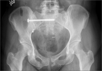
Myocardial geometry, function altered in obese children
Obese children and adolescents show significant adverse alterations in myocardial geometry and function on echocardiography, compared with normal-weight children, according to a report published online Oct. 8 in JACC: Cardiovascular Imaging.
In a prospective, cross-sectional cohort study in Germany, researchers performed two-dimensional echocardiography in 61 obese and 40 nonobese participants aged 8-21 years. All the children were white, free of known disease, and not taking any medications, said Dr. Norman Mangner of the University of Leipzig and Heart Center Leipzig and his associates.
Global ejection fraction was normal in both study groups. However, the obese participants showed thickened LV walls and larger chamber dimensions; as a result, their calculated LV mass and LV mass index were roughly 40% higher than those of nonobese children. Left atrial volume, LA volume index, right atrial area, and right ventricular diameter all were also increased, compared with those of nonobese children. In addition, z scores for LA diameter were above the 95th percentile in a significantly higher percentage of the obese participants (33.3%) than nonobese participants (10%), the investigators said (J. Am. Coll. Cardiol. Img. 2014 Oct. 8 [doi: 10.1016/j.jcmg.2014.08.006]).
Regarding myocardial function, both tissue Doppler-derived peak systolic velocity and deformation in the basoseptal region were reduced in the obese children. Average longitudinal LV strain, strain rate, and displacement – all measures of longitudinal function – were significantly reduced. Average LV circumferential strain was significantly blunted in the obese participants, but the average LV circumferential strain rate and radial function were not significantly different between the two study groups. And diastolic function was decreased in the obese children, as evidenced by their reduced mitral E- to mitral A-wave peak velocity (E/A ratio), reduced mitral annulus tissue Doppler imaging (TDI) peak E-wave velocity, and increased E/E’ ratios.
“It is important to note that [these changes] do not necessarily translate into clinically relevant functional impairment,” Dr. Mangner and his associates said.
A longitudinal study is needed to clarify the clinical significance of these alterations and to explore whether weight loss will reverse them, they added.
This study was supported in part by grants from the German Research Foundation and the Clinical Research Group. One of Dr. Mangner’s associates reported ties to Medtronic, St. Jude Medical, Claret Medical, Boston Scientific, and Edwards; Dr. Mangner and his other associates reported having no financial disclosures.
Key clinical point: Obese children and adolescents have increased left ventricular mass, decreased LV diastolic function, and other adverse myocardial changes.
Major finding: Obese children and adolescents showed thickened LV walls and larger chamber dimensions, so their calculated LV mass and LV mass index were about 40% higher than those of nonobese children.
Data source: A prospective cross-sectional cohort study involving 61 obese and 40 nonobese participants aged 8-21 years who underwent cardiac echocardiography.
Disclosures: This study was supported in part by grants from the German Research Foundation and the Clinical Research Group. One of Dr. Mangner’s associates reported ties to Medtronic, St. Jude Medical, Claret Medical, Boston Scientific, and Edwards; Dr. Mangner and his other associates reported having no financial disclosures.

Acupuncture Does Not Improve Chronic Knee Pain
In patients older than 50 with moderate or severe chronic knee pain, neither laser nor needle acupuncture conferred benefit over sham for pain or function, according to a study published in the October 1 issue of JAMA.
Rana S. Hinman, PhD, from the University of Melbourne in Australia, and colleagues randomly assigned 282 patients (50 or older) with chronic knee pain to no acupuncture (control group, n = 71) or needle (n = 70), laser (n = 71), or sham laser (n = 70) acupuncture. Treatments were delivered for 12 weeks. Participants and acupuncturists were blinded to laser and sham laser acupuncture. Control participants were unaware of the trial.
Primary outcomes were average knee pain (numeric rating scale, 0 [no pain] to 10 [worst pain possible]; minimal clinically important difference [MCID], 1.8 units) and physical function (Western Ontario and McMaster Universities Osteoarthritis Index, 0 [no difficulty] to 68 [extreme difficulty]; MCID, 6 units) at 12 weeks.
Secondary outcomes included other pain and function measures, quality of life, global change, and one-year follow-up. Analyses were by intention-to-treat using multiple imputations for missing outcome data.
There were no significant differences in primary outcomes between active and sham acupuncture at 12 weeks or one year. Both needle and laser acupuncture resulted in modest improvements in pain compared with control at 12 weeks that were not maintained at one year. Needle acupuncture improved physical function at 12 weeks compared with control but was not different from sham acupuncture and was not maintained at one year. There were no differences for most secondary outcomes and no serious adverse events.
The authors noted that incidental factors such as treatment setting, patient expectations and attitudes (such as optimism), acupuncturist's confidence in treatment, and patient and acupuncturist interaction may influence outcomes.
"In our study, benefits of acupuncture were exclusively attributed to incidental effects, given the lack of significant differences between active acupuncture and sham treatment. Continuous subjective measures, such as pain and self-reported physical function, as used in our study, are particularly subject to placebo responses,” stated investigators. "In patients older than 50 years with moderate or severe chronic knee pain, neither laser nor needle acupuncture conferred benefit over sham for pain or function. Our findings do not support acupuncture for these patients."
Suggested Reading
Hinman RS, McCrory P, Pirotta M, et al. Acupuncture for chronic knee pain: a randomized clinical trial. JAMA. 2014;312(13):1313-22.
In patients older than 50 with moderate or severe chronic knee pain, neither laser nor needle acupuncture conferred benefit over sham for pain or function, according to a study published in the October 1 issue of JAMA.
Rana S. Hinman, PhD, from the University of Melbourne in Australia, and colleagues randomly assigned 282 patients (50 or older) with chronic knee pain to no acupuncture (control group, n = 71) or needle (n = 70), laser (n = 71), or sham laser (n = 70) acupuncture. Treatments were delivered for 12 weeks. Participants and acupuncturists were blinded to laser and sham laser acupuncture. Control participants were unaware of the trial.
Primary outcomes were average knee pain (numeric rating scale, 0 [no pain] to 10 [worst pain possible]; minimal clinically important difference [MCID], 1.8 units) and physical function (Western Ontario and McMaster Universities Osteoarthritis Index, 0 [no difficulty] to 68 [extreme difficulty]; MCID, 6 units) at 12 weeks.
Secondary outcomes included other pain and function measures, quality of life, global change, and one-year follow-up. Analyses were by intention-to-treat using multiple imputations for missing outcome data.
There were no significant differences in primary outcomes between active and sham acupuncture at 12 weeks or one year. Both needle and laser acupuncture resulted in modest improvements in pain compared with control at 12 weeks that were not maintained at one year. Needle acupuncture improved physical function at 12 weeks compared with control but was not different from sham acupuncture and was not maintained at one year. There were no differences for most secondary outcomes and no serious adverse events.
The authors noted that incidental factors such as treatment setting, patient expectations and attitudes (such as optimism), acupuncturist's confidence in treatment, and patient and acupuncturist interaction may influence outcomes.
"In our study, benefits of acupuncture were exclusively attributed to incidental effects, given the lack of significant differences between active acupuncture and sham treatment. Continuous subjective measures, such as pain and self-reported physical function, as used in our study, are particularly subject to placebo responses,” stated investigators. "In patients older than 50 years with moderate or severe chronic knee pain, neither laser nor needle acupuncture conferred benefit over sham for pain or function. Our findings do not support acupuncture for these patients."
Suggested Reading
Hinman RS, McCrory P, Pirotta M, et al. Acupuncture for chronic knee pain: a randomized clinical trial. JAMA. 2014;312(13):1313-22.
Suggested Reading
Hinman RS, McCrory P, Pirotta M, et al. Acupuncture for chronic knee pain: a randomized clinical trial. JAMA. 2014;312(13):1313-22.