User login
Simultaneous Bilateral Functional Radiography in Ulnar Collateral Ligament Lesion of the Thumb: An Original Technique
Gamekeeper’s or skier’s thumb is caused by an injury to the ulnar collateral ligament (UCL) of the metacarpophalangeal (MCP) joint of the thumb. The mechanism of injury is forced radial and palmar abduction and hyperextension.
This lesion was initially described in 1955 by Campbell.1 It occurred in gamekeepers who worked in preserves in Scotland. The UCL was injured because of the way they killed rabbits—hence, gamekeeper’s thumb. Now these injuries are more common in skiers—skier’s thumb. In skiers, the mechanism of injury is the force exerted by the ski pole strap on the thumb during a fall. This injury is also seen in breakdancers.1,2
Different lesions can result, the most common being that of the UCL. The UCL lesion may be partial, with no joint instability,3,4 or total, with instability and subdislocation of the proximal phalanx.5-9 Rupture of the thumb adductor aponeurosis and displacement of the long extensor have been described as the cause of thumb instability.6-8
UCL rupture can occur in its extension or can cause a fracture-tearing in the proximal phalanx.9-12 Intra-articular fractures are sometimes found. The essential problem in UCL injuries is the impossibility of spontaneous healing once the rupture is complete, because of the Stener effect. (When the UCL ruptures, its proximal part retracts and runs above the fibrous expansion of the adductor muscle, which is interposed between the 2 parts of the ruptured UCL and prevents healing, even if the thumb is immobilized.) In these cases, only surgery can repair the lesion.2
In any thumb injury, particularly one caused by hyperabduction, a UCL lesion should be considered. The main problem is diagnosing sprain severity, which is evidenced by the degree of joint hypermobility. Radiologic examination should be performed in all cases to rule out fracture with tear, posterior capsular tear, palmar plate tear, and palmar subdislocation of the proximal phalanx, all of which are associated with UCL tearing.7-9
If the diagnosis is suspected, and radiographs show no fracture, comparative radiographs should be obtained in forced valgus.
Technique
We report on a simple, reliable, reproducible method that allows the patient’s thumbs to be compared, under the same force application conditions, on a single radiograph. This technique reduces the patient’s and examiner’s exposure to x-rays and is well tolerated by the patient. Anesthesia for the thumb is usually not necessary.
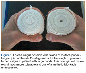
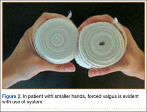
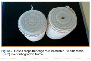
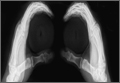
In each hand, the patient holds a cylindrical object, such as a drinking glass (standard diameter, 7.5-8.5 cm). We use an elastic crepe bandage roll (diameter, 7.5 cm; width, 10 cm). This roll is common in emergency departments (EDs) and easily accessible. The patient holds the rolls in his or her hands with the thumbs in the posteroanterior position (Figures 1–3) and places himself or herself on a 18×24-cm frame or directly on the radiography table.
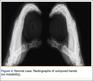
Both thumbs are captured on a single functional radiograph for comparison of forced valgus of the MCP joints, as in our example cases. The patients provided written informed consent for print and electronic publication of these case reports.
Case Reports
Control Case
The single functional radiograph of both thumbs showed no evidence of joint laxity on the valgus stress test (Figure 4).
Case 1
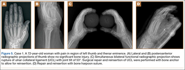
A 72-year-old woman landed on her left hand when she fell backward while supporting the hand on a piece of furniture. She presented to the ED with pain in the region of the thumb and thenar eminence. Posteroanterior and lateral radiograph projections showed no significant bone injury (Figure 5). Given the patient’s persistent pain, the traumatologist suspected damage to the thumb UCL, so a simultaneous bilateral functional radiographic projection was obtained. The projection showed joint laxity, implying damage to the thumb UCL. Repair and reinsertion of the UCL were performed using a bone harpoon suture.
Case 2
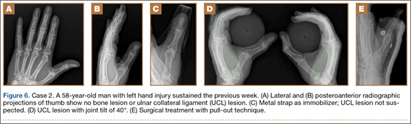
A 58-year-old man sustained a left hand injury when, using both hands, he tried to catch hold of a falling wooden plank. When he presented to the ED the following week, he was given a diagnosis of thumb contusion and forced hyperabduction and was wearing a metal strap for immobilization. Radiographs showed no bone damage (Figure 6). Thumb UCL injury was suspected on the basis of the physical examination findings and the mechanism of injury. A bilateral simultaneous functional radiographic projection showed significant joint laxity. Surgical treatment with the pull-out technique was performed.
Case 3
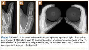
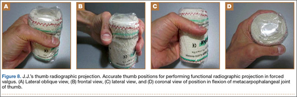
A 44-year-old woman experienced forced traction from a dog leash and presented to the ED with pain in the right thumb region. Radiographs showed no bone damage (Figure 7). Thumb UCL injury was suspected. A bilateral simultaneous functional radiographic projection showed slight joint laxity, a sprain was diagnosed, and plaster bandaging was applied. Figures 8A–8D show the accurate thumb positions for performing the functional radiograph in forced valgus. We call the technique J.J.’s thumb radiographic projection.
Discussion
Examination using the stress test to cause joint tilt is crucial in making an accurate diagnosis and deciding on the most appropriate therapeutic approach.10 Most authors accept that surgical management is required in joint tilts over 30º, as these involve complete UCL rupture.10-12
The MCP joint must be examined in flexion, when the main fascicle of the UCL is tight, and not in extension, when the main fascicle of the UCL is relaxed. If we examine the thumb in extension, radial deviations may occur that are not caused by joint instability. Tilt here must be compared with that of the healthy side.11
Early diagnosis and adequate management are essential, as unnoticed or undervalued injuries can progress to painful sequelae, associated with stiffness, instability, and osteoarthritis, with evident harm to the grip and pinch functions of the hand. In many cases, clinical evidence of MCP joint instability is difficult. The radiologic diagnosis is usually obtained with comparative radiographs in forced valgus of both thumbs.
The forced valgus maneuver typically is performed by the examiner, who must stay with the patient in the radiography room and wear radiologic protection. Incredibly, some patients must force the valgus themselves.
The maneuver we have described clearly has complications, as it is painful, and some patients are uncooperative. Usually the thumb is anesthetized, and the examiner assumes the exposure to x-rays. The valgus deviation force that can be applied during stability testing may lead to further disruption of a partially torn ligament or displacement of a ruptured ligament if the overforced maneuver is performed.13,14 That does not occur with our technique. On the other hand, the forces applied to the thumbs must be symmetrical for comparison purposes. The way to prevent these inconveniences is to perform the forced valgus maneuver over both thumbs simultaneously, under the same force application conditions and on a single radiograph, without requiring the examiner to remain with the patient in the radiography room.
Heim15 designed a system for simultaneous functional radiographs, but an apparatus must be built to adapt it to the frame of the radiography table, and the technique involves hyperpronating both hands and bandaging them to the forearm—which is uncomfortable and bothersome for patients and, in our opinion, has a poor application in high-volume EDs.
The technique of having the patient hold a bandage roll (J.J.’s thumb radiographic projection) offers several advantages:
1. The thumb can be placed in flexion, tightening the main fascicle of the UCL, which is how the UCL must be examined.
2. Forced valgus is allowed. Holding a water glass involves opening the thumb and the necessary stability of the MCP joint of the thumb (grip function of thumb); this radiographic technique is functional.
3. The examiner need not stay with the patient in the radiography room or be exposed to x-rays.
4. The bandage roll is thick enough to generate forced valgus in a patient with large hands. The nonrigid roll makes the examination more tolerable and avoids overforced valgus, eliminating the need for anesthetic blockade.
5. The technique is accessible and simple. In fact, there is no need to remove the roll from its wrapping.
1. Campbell CS. Gamekeeper’s thumb. J Bone Joint Surg Br. 1955;37(1):148-149.
2. Stener B. Displacement of the ruptured ulnar collateral ligament of the metacarpophalangeal joint of the thumb: a clinical and anatomic study. J Bone Joint Surg Br. 1962;44(4):869-879.
3. Stener B. Hyperextension injuries to the metacarpophalangeal joint of the thumb: rupture of ligaments, fracture of sesamoid bones, rupture of flexor pollicis brevis. An anatomical and clinical study. Acta Chir Scand. 1963;125:275-293.
4. Coonrad RW, Goldner JL. A study of the pathological findings and treatment in soft-tissue injury of the thumb metacarpophalangeal joint. With a clinical study of the normal range of motion in one thousand thumbs and a study of post mortem findings of ligamentous structures in relation to function. J Bone Joint Surg Am. 1968;50(3):439-451.
5. Parikh M, Nahigian S, Froimson A. Gamekeeper’s thumb. Plast Reconstr Surg. 1976;58(1):24-31.
6. Kaplan EB. The pathology and treatment of radial subluxation of the thumb with ulnar displacement of the head of the first metacarpal. J Bone Joint Surg Am. 1961;43:541-546.
7. Yamanaka K, Yoshida K, Inoue H, Inoue A, Miyagi T. Locking of the metacarpophalangeal joint of the thumb. J Bone Joint Surg Am. 1985;67(5):782-787.
8. Sennwald G, Segmüller G, Egli A. The late reconstruction of the ligament of the metacarpo-phalangeal joint of the thumb [in English, French]. Ann Chir Main. 1987;6(1):15-24.
9. Smith RJ. Post-traumatic instability of the metacarpophalangeal joint of the thumb. J Bone Joint Surg Am. 1977;59(1):14-21.
10. Louis DS, Huebner JJ Jr, Hankin FM. Rupture and displacement of the ulnar collateral ligament of the metacarpophalangeal joint of the thumb. Preoperative diagnosis. J Bone Joint Surg Am. 1986;68(9):1320-1326.
11. Heyman P, Gelberman RH, Duncan K, Hipp JA. Injuries of the ulnar collateral ligament of the thumb metacarpophalangeal joint. Biomechanical and prospective clinical studies on the usefulness of valgus stress testing. Clin Orthop Relat Res. 1993;(292):165-171.
12. Ritting AW, Baldwin PC, Rodner CM. Ulnar collateral ligament injury of the thumb metacarpophalangeal joint. Clin J Sport Med. 2010;20(2):106-112.
13. Cooper JG, Johnstone AJ, Hider P, Ardagh MW. Local anaesthetic infiltration increases the accuracy of assessment of ulnar collateral ligament injuries. Emerg Med Australas. 2005;17(2):132-136.
14. Noszian IM, Dinkhauser LM, Straub GM, Orthner E. Ulnar collateral ligament injuries of the thumb. Dislocation caused by stress radiography in 2 cases. Acta Orthop Scand. 1995;66(2):156-157.
15. Heim U. Simultaneous functional bilateral radiographies of the metacarpophalangeal joint of the thumb in hyper-pronation [in French]. Ann Chir Main. 1982;1(2):183-186.
Gamekeeper’s or skier’s thumb is caused by an injury to the ulnar collateral ligament (UCL) of the metacarpophalangeal (MCP) joint of the thumb. The mechanism of injury is forced radial and palmar abduction and hyperextension.
This lesion was initially described in 1955 by Campbell.1 It occurred in gamekeepers who worked in preserves in Scotland. The UCL was injured because of the way they killed rabbits—hence, gamekeeper’s thumb. Now these injuries are more common in skiers—skier’s thumb. In skiers, the mechanism of injury is the force exerted by the ski pole strap on the thumb during a fall. This injury is also seen in breakdancers.1,2
Different lesions can result, the most common being that of the UCL. The UCL lesion may be partial, with no joint instability,3,4 or total, with instability and subdislocation of the proximal phalanx.5-9 Rupture of the thumb adductor aponeurosis and displacement of the long extensor have been described as the cause of thumb instability.6-8
UCL rupture can occur in its extension or can cause a fracture-tearing in the proximal phalanx.9-12 Intra-articular fractures are sometimes found. The essential problem in UCL injuries is the impossibility of spontaneous healing once the rupture is complete, because of the Stener effect. (When the UCL ruptures, its proximal part retracts and runs above the fibrous expansion of the adductor muscle, which is interposed between the 2 parts of the ruptured UCL and prevents healing, even if the thumb is immobilized.) In these cases, only surgery can repair the lesion.2
In any thumb injury, particularly one caused by hyperabduction, a UCL lesion should be considered. The main problem is diagnosing sprain severity, which is evidenced by the degree of joint hypermobility. Radiologic examination should be performed in all cases to rule out fracture with tear, posterior capsular tear, palmar plate tear, and palmar subdislocation of the proximal phalanx, all of which are associated with UCL tearing.7-9
If the diagnosis is suspected, and radiographs show no fracture, comparative radiographs should be obtained in forced valgus.
Technique
We report on a simple, reliable, reproducible method that allows the patient’s thumbs to be compared, under the same force application conditions, on a single radiograph. This technique reduces the patient’s and examiner’s exposure to x-rays and is well tolerated by the patient. Anesthesia for the thumb is usually not necessary.
In each hand, the patient holds a cylindrical object, such as a drinking glass (standard diameter, 7.5-8.5 cm). We use an elastic crepe bandage roll (diameter, 7.5 cm; width, 10 cm). This roll is common in emergency departments (EDs) and easily accessible. The patient holds the rolls in his or her hands with the thumbs in the posteroanterior position (Figures 1–3) and places himself or herself on a 18×24-cm frame or directly on the radiography table.
Both thumbs are captured on a single functional radiograph for comparison of forced valgus of the MCP joints, as in our example cases. The patients provided written informed consent for print and electronic publication of these case reports.
Case Reports
Control Case
The single functional radiograph of both thumbs showed no evidence of joint laxity on the valgus stress test (Figure 4).
Case 1
A 72-year-old woman landed on her left hand when she fell backward while supporting the hand on a piece of furniture. She presented to the ED with pain in the region of the thumb and thenar eminence. Posteroanterior and lateral radiograph projections showed no significant bone injury (Figure 5). Given the patient’s persistent pain, the traumatologist suspected damage to the thumb UCL, so a simultaneous bilateral functional radiographic projection was obtained. The projection showed joint laxity, implying damage to the thumb UCL. Repair and reinsertion of the UCL were performed using a bone harpoon suture.
Case 2
A 58-year-old man sustained a left hand injury when, using both hands, he tried to catch hold of a falling wooden plank. When he presented to the ED the following week, he was given a diagnosis of thumb contusion and forced hyperabduction and was wearing a metal strap for immobilization. Radiographs showed no bone damage (Figure 6). Thumb UCL injury was suspected on the basis of the physical examination findings and the mechanism of injury. A bilateral simultaneous functional radiographic projection showed significant joint laxity. Surgical treatment with the pull-out technique was performed.
Case 3
A 44-year-old woman experienced forced traction from a dog leash and presented to the ED with pain in the right thumb region. Radiographs showed no bone damage (Figure 7). Thumb UCL injury was suspected. A bilateral simultaneous functional radiographic projection showed slight joint laxity, a sprain was diagnosed, and plaster bandaging was applied. Figures 8A–8D show the accurate thumb positions for performing the functional radiograph in forced valgus. We call the technique J.J.’s thumb radiographic projection.
Discussion
Examination using the stress test to cause joint tilt is crucial in making an accurate diagnosis and deciding on the most appropriate therapeutic approach.10 Most authors accept that surgical management is required in joint tilts over 30º, as these involve complete UCL rupture.10-12
The MCP joint must be examined in flexion, when the main fascicle of the UCL is tight, and not in extension, when the main fascicle of the UCL is relaxed. If we examine the thumb in extension, radial deviations may occur that are not caused by joint instability. Tilt here must be compared with that of the healthy side.11
Early diagnosis and adequate management are essential, as unnoticed or undervalued injuries can progress to painful sequelae, associated with stiffness, instability, and osteoarthritis, with evident harm to the grip and pinch functions of the hand. In many cases, clinical evidence of MCP joint instability is difficult. The radiologic diagnosis is usually obtained with comparative radiographs in forced valgus of both thumbs.
The forced valgus maneuver typically is performed by the examiner, who must stay with the patient in the radiography room and wear radiologic protection. Incredibly, some patients must force the valgus themselves.
The maneuver we have described clearly has complications, as it is painful, and some patients are uncooperative. Usually the thumb is anesthetized, and the examiner assumes the exposure to x-rays. The valgus deviation force that can be applied during stability testing may lead to further disruption of a partially torn ligament or displacement of a ruptured ligament if the overforced maneuver is performed.13,14 That does not occur with our technique. On the other hand, the forces applied to the thumbs must be symmetrical for comparison purposes. The way to prevent these inconveniences is to perform the forced valgus maneuver over both thumbs simultaneously, under the same force application conditions and on a single radiograph, without requiring the examiner to remain with the patient in the radiography room.
Heim15 designed a system for simultaneous functional radiographs, but an apparatus must be built to adapt it to the frame of the radiography table, and the technique involves hyperpronating both hands and bandaging them to the forearm—which is uncomfortable and bothersome for patients and, in our opinion, has a poor application in high-volume EDs.
The technique of having the patient hold a bandage roll (J.J.’s thumb radiographic projection) offers several advantages:
1. The thumb can be placed in flexion, tightening the main fascicle of the UCL, which is how the UCL must be examined.
2. Forced valgus is allowed. Holding a water glass involves opening the thumb and the necessary stability of the MCP joint of the thumb (grip function of thumb); this radiographic technique is functional.
3. The examiner need not stay with the patient in the radiography room or be exposed to x-rays.
4. The bandage roll is thick enough to generate forced valgus in a patient with large hands. The nonrigid roll makes the examination more tolerable and avoids overforced valgus, eliminating the need for anesthetic blockade.
5. The technique is accessible and simple. In fact, there is no need to remove the roll from its wrapping.
1. Campbell CS. Gamekeeper’s thumb. J Bone Joint Surg Br. 1955;37(1):148-149.
2. Stener B. Displacement of the ruptured ulnar collateral ligament of the metacarpophalangeal joint of the thumb: a clinical and anatomic study. J Bone Joint Surg Br. 1962;44(4):869-879.
3. Stener B. Hyperextension injuries to the metacarpophalangeal joint of the thumb: rupture of ligaments, fracture of sesamoid bones, rupture of flexor pollicis brevis. An anatomical and clinical study. Acta Chir Scand. 1963;125:275-293.
4. Coonrad RW, Goldner JL. A study of the pathological findings and treatment in soft-tissue injury of the thumb metacarpophalangeal joint. With a clinical study of the normal range of motion in one thousand thumbs and a study of post mortem findings of ligamentous structures in relation to function. J Bone Joint Surg Am. 1968;50(3):439-451.
5. Parikh M, Nahigian S, Froimson A. Gamekeeper’s thumb. Plast Reconstr Surg. 1976;58(1):24-31.
6. Kaplan EB. The pathology and treatment of radial subluxation of the thumb with ulnar displacement of the head of the first metacarpal. J Bone Joint Surg Am. 1961;43:541-546.
7. Yamanaka K, Yoshida K, Inoue H, Inoue A, Miyagi T. Locking of the metacarpophalangeal joint of the thumb. J Bone Joint Surg Am. 1985;67(5):782-787.
8. Sennwald G, Segmüller G, Egli A. The late reconstruction of the ligament of the metacarpo-phalangeal joint of the thumb [in English, French]. Ann Chir Main. 1987;6(1):15-24.
9. Smith RJ. Post-traumatic instability of the metacarpophalangeal joint of the thumb. J Bone Joint Surg Am. 1977;59(1):14-21.
10. Louis DS, Huebner JJ Jr, Hankin FM. Rupture and displacement of the ulnar collateral ligament of the metacarpophalangeal joint of the thumb. Preoperative diagnosis. J Bone Joint Surg Am. 1986;68(9):1320-1326.
11. Heyman P, Gelberman RH, Duncan K, Hipp JA. Injuries of the ulnar collateral ligament of the thumb metacarpophalangeal joint. Biomechanical and prospective clinical studies on the usefulness of valgus stress testing. Clin Orthop Relat Res. 1993;(292):165-171.
12. Ritting AW, Baldwin PC, Rodner CM. Ulnar collateral ligament injury of the thumb metacarpophalangeal joint. Clin J Sport Med. 2010;20(2):106-112.
13. Cooper JG, Johnstone AJ, Hider P, Ardagh MW. Local anaesthetic infiltration increases the accuracy of assessment of ulnar collateral ligament injuries. Emerg Med Australas. 2005;17(2):132-136.
14. Noszian IM, Dinkhauser LM, Straub GM, Orthner E. Ulnar collateral ligament injuries of the thumb. Dislocation caused by stress radiography in 2 cases. Acta Orthop Scand. 1995;66(2):156-157.
15. Heim U. Simultaneous functional bilateral radiographies of the metacarpophalangeal joint of the thumb in hyper-pronation [in French]. Ann Chir Main. 1982;1(2):183-186.
ICM exposure associated with higher risk of thyroid dysfunction
After adjusting for variables, patients with iodinated contrast media (ICM) exposure had a significantly higher risk of thyroid dysfunction (hazard ratio, 1.46; 95% confidence interval, 1.29-1.66), compared with that of patients in the non-ICM exposure group, wrote the authors of a newly published study in the Journal of Clinical Endocrinology & Metabolism.
Lead author Dr. Edy Kornelius and associates examined 19,642 cases and 78,568 matched controls, recruited from the general population in Taiwan, in a 6-year cohort study. A total of 383 ICM-exposed patients had thyroid dysfunction (cumulative risk: 1.9%), compared with 1,252 patients without ICM exposure (cumulative risk: 1.5%). The number needed to harm (NNH) was 1 for every 250 people, the investigators noted.

In the subgroup analysis, the adjusted hazard ratios of hyperthyroidism and hypothyroidism were 1.22 (95% CI, 1.04-1.44) and 2.00 (95% CI, 1.65-2.44) when compared with controls. Patients with a higher Charlson’s Comorbidity Index were generally at a higher risk of thyroid dysfunction.
“In this study, we found a 22% increased risk of hyperthyroidism in ICM-exposed patients,” the authors wrote. “Although ICM-related imaging and interventional studies improve the disease diagnosis rate and quality of health, physicians should be aware of the complications of ICM and should apply it cautiously in clinical practice.”
For the full article, click here: J. Clin. Endocrinol. Metab. 2015 (doi:10.1210/JC.2015-2329).
After adjusting for variables, patients with iodinated contrast media (ICM) exposure had a significantly higher risk of thyroid dysfunction (hazard ratio, 1.46; 95% confidence interval, 1.29-1.66), compared with that of patients in the non-ICM exposure group, wrote the authors of a newly published study in the Journal of Clinical Endocrinology & Metabolism.
Lead author Dr. Edy Kornelius and associates examined 19,642 cases and 78,568 matched controls, recruited from the general population in Taiwan, in a 6-year cohort study. A total of 383 ICM-exposed patients had thyroid dysfunction (cumulative risk: 1.9%), compared with 1,252 patients without ICM exposure (cumulative risk: 1.5%). The number needed to harm (NNH) was 1 for every 250 people, the investigators noted.
In the subgroup analysis, the adjusted hazard ratios of hyperthyroidism and hypothyroidism were 1.22 (95% CI, 1.04-1.44) and 2.00 (95% CI, 1.65-2.44) when compared with controls. Patients with a higher Charlson’s Comorbidity Index were generally at a higher risk of thyroid dysfunction.
“In this study, we found a 22% increased risk of hyperthyroidism in ICM-exposed patients,” the authors wrote. “Although ICM-related imaging and interventional studies improve the disease diagnosis rate and quality of health, physicians should be aware of the complications of ICM and should apply it cautiously in clinical practice.”
For the full article, click here: J. Clin. Endocrinol. Metab. 2015 (doi:10.1210/JC.2015-2329).
Madelung Deformity and Extensor Tendon Rupture
Extensor tendon rupture in chronic Madelung deformity, as a result of tendon attrition on the dislocated distal ulna, occurs infrequently. However, it is often seen in patients with rheumatoid arthritis. This issue has been reported in only a few English-language case reports. Here we report a case of multiple tendon ruptures in a previously undiagnosed Madelung deformity. The patient provided written informed consent for print and electronic publication of this case report.
Case Report
A 56-year-old active woman presented with 50 days’ inability to extend the fourth and fifth fingers of her dominant right hand. The loss of finger extension progressed, over several weeks, to involve the third finger as well. The first 2 tendon ruptures had been triggered by lifting a light grocery bag, when she noticed a sharp sudden pain and “pop.” The third rupture occurred spontaneously with a snapping sound the night before surgery.
The patient had observed some prominence on the ulnar side of her right wrist since childhood but had never experienced any pain or functional disability. There was neither history of trauma, inflammatory disease, diabetes mellitus, or infection, nor positive family history of similar wrist deformity.
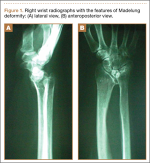
The physical examination showed a dorsally subluxated distal radioulnar joint, prominent ulnar styloid, and mild ulnar and volar deviation of the wrist along with limitation of wrist dorsiflexion. Complete loss of active extension of the 3 ulnar fingers was demonstrated, while neurovascular status and all other hand evaluations were normal. The wrist radiographs confirmed the typical findings of Madelung deformity (Figure 1).
Repair of the ruptured tendons and resection of the prominent distal ulna (Darrach procedure) was planned. (Given the patient’s age and evidence of degenerative changes in the radiocarpal joint, correction of the Madelung deformity did not seem necessary). At time of surgery, the recently ruptured third finger extensor tendon was easily found and approximated, and end-to-end repair was performed. The fourth and fifth fingers, however, had to be fished out more proximally from dense granulation tissue. After the distal ulna was resected for a distance of 1.5 cm, meticulous repair of the ulnar collateral ligament and the capsule and periosteum over the end of the ulna was performed. Then, for grafting of the ruptured tendons, the extensor indicis proprius tendon was isolated and transected at the second metacarpophalangeal joint level. A piece of this tendon was used as interpositional graft for the fourth extensor tendon, and the main tendon unit was transferred to the fifth finger extensor. The extensor digiti quinti tendon, which was about to rupture, was further reinforced by suturing it side to side to the muscle and tendon of the extensor indicis proprius (Figure 2).

Postoperatively, the wrist was kept in extension in a cast for 3 weeks while the fingers were free for active movement. A removable wrist splint was used for an additional month. At 3-month follow-up, the patient had regained full and strong finger extension and wrist motion.
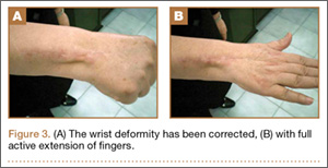
At 3-year follow-up, the patient was pain-free, and had full extension of all fingers, full forearm rotation, and near-normal motion (better than her preoperative motion). The grip power on the operated right hand was 215 N, and pinch power was 93 N. (The values for the left side were 254 N and 83 N, respectively, using the Jamar hydraulic hand dynamometer [Patterson Medical].) The patient has had no additional tendon rupture (Figure 3).
Discussion
Madelung deformity was first described by Madelung in 1878 and several cases have reported this deformity. However, extensor tendon rupture caused by Madelung deformity is very rare, reported in few cases.1
Extensor tendon rupture caused by chronic Madelung deformity has been reported few times in the English literature. Goodwin1 apparently published the first report of such an occurrence in 1979. Ducloyer and colleagues2 from France reported 6 cases of extensor tendon rupture as a result of inferior distal radioulnar joint deformity of Madelung. Jebson and colleagues3 reported bilateral spontaneous extensor tendon ruptures in Madelung deformity in 1992.
The mechanism of tendon rupture seems to be mechanical, resulting from continuous rubbing and erosion of tendons over the deformed ulnar head, which has a rough irregular surface4 and leads to fraying of the tendons and eventual rupture and retraction of the severed tendon ends. This rupture usually progresses stepwise from more medial to the lateral tendons.2 Older patients are, therefore, subject to chronic repetitive attritional trauma leading to tendon rupture.
Tendons may rupture as a result of a variety of conditions, such as chronic synovitis in rheumatoid arthritis, systemic lupus erythematosus, mixed connective tissue disease, or crystal deposition in gout.5-8 Some other metabolic or endocrine conditions that involve tendon ruptures include diabetes mellitus, chronic renal failure, and hyperparathyroidism. Steroid injection into the tendons also has a detrimental effect on tendon integrity and may cause tendon tear.9 Mechanical factors, such as erosion on bony prominences, are well-known etiologies for tendon rupture, as commonly seen in rheumatoid arthritis, and have been reported in Kienböck disease,10 thumb carpometacarpal arthritis,11 Colles fracture, scaphoid fracture nonunion,12 and Madelung deformity.
Conclusion
Our case reflects the usual middle-aged female presentation of such a tendon rupture. The tendon ruptures were spontaneous in the reported order of ulnar to radial, beginning with the little and ring fingers, and progressed radially. The patient had isolated Madelung deformity with no other sign of dyschondrosteosis13 or dwarfism, conditions commonly mentioned in association with Madelung deformity. This case report should raise awareness about possible tendon rupture in any chronic case of Madelung deformity.
1. Goodwin DR, Michels CH, Weissman SL. Spontaneous rupture of extensor tendons in Madelung’s deformity. Hand. 1979;11(1):72-75.
2. Ducloyer P, Leclercq C, Lisfrance R, Saffar P. Spontaneous rupture of the extensor tendons of the fingers in Madelung’s deformity. J Hand Surg Br. 1991;16(3):329-333.
3. Jebson PJ, Blair WF. Bilateral spontaneous extensor tendon ruptures in Madelung’s deformity. J Hand Surg Am. 1992;17(2):277-280.
4. Schulstad I. Madelung’s deformity with extensor tendon rupture. Case report. Scand J Plast Reconstr Surg. 1971;5(2):153-155.
5. Gong HS, Lee JO, Baek GH, et al. Extensor tendon rupture in rheumatoid arthritis: a survey of patients between 2005 and 2010 at five Korean hospitals. Hand Surg. 2012;17(1):43-47.
6. Oishi H, Oda R, Morisaki S, Fujiwara H, Tokunaga D, Kubo T. Spontaneous tendon rupture of the extensor digitrum communis in systemic lupus erythematosus. Mod Rheumatol. 2013;23(3);608-610.
7. Kobayashi A, Futami T, Tadano I, Fujita M. Spontaneous rupture of extensor tendons at the wrist in a patient with mixed connective tissue disease. Mod Rheumatol. 2002;12(3):256-258.
8. Iwamoto T, Toki H, Ikari K, Yamanaka H, Momohara S. Multiple extensor tendon ruptures caused by tophaceous gout. Mod Rheumatol. 2010;20(2):210-212.
9. Nquyen ML, Jones NF. Rupture of both abductor pollicis longus and extensor pollicis brevis tendon after steroid injection for de quervain tenosynovitis. Plast Reconstr Surg. 2012;129(5):883e-886e.
10. Hernández-Cortés P, Pajares-López M, Gómez-Sánchez R, Garrido-Gómez, Lara-Garcia F. Rupture of extensor tendon secondary to previously undiagnosed Kienböck disease. J Plast Surg Hand Surg. 2012;46(3-4):291-293.
11. Apard T, Marcucci L, Jarriges J. Spontaneous rupture of extensor pollicis longus in isolated trapeziometacarpal arthritis. Chir Main. 2011;30(5):349-351.
12. Harvey FJ, Harvey PM. Three rare causes of extensor tendon rupture. J Hand Surg Am. 1989;14(6):957-962.
13. Duro EA, Prado GS. Clinical variations in Léri-Weill dyschondrosteosis. An Esp Pediatr. 1990;33(5):461-463.
Extensor tendon rupture in chronic Madelung deformity, as a result of tendon attrition on the dislocated distal ulna, occurs infrequently. However, it is often seen in patients with rheumatoid arthritis. This issue has been reported in only a few English-language case reports. Here we report a case of multiple tendon ruptures in a previously undiagnosed Madelung deformity. The patient provided written informed consent for print and electronic publication of this case report.
Case Report
A 56-year-old active woman presented with 50 days’ inability to extend the fourth and fifth fingers of her dominant right hand. The loss of finger extension progressed, over several weeks, to involve the third finger as well. The first 2 tendon ruptures had been triggered by lifting a light grocery bag, when she noticed a sharp sudden pain and “pop.” The third rupture occurred spontaneously with a snapping sound the night before surgery.
The patient had observed some prominence on the ulnar side of her right wrist since childhood but had never experienced any pain or functional disability. There was neither history of trauma, inflammatory disease, diabetes mellitus, or infection, nor positive family history of similar wrist deformity.
The physical examination showed a dorsally subluxated distal radioulnar joint, prominent ulnar styloid, and mild ulnar and volar deviation of the wrist along with limitation of wrist dorsiflexion. Complete loss of active extension of the 3 ulnar fingers was demonstrated, while neurovascular status and all other hand evaluations were normal. The wrist radiographs confirmed the typical findings of Madelung deformity (Figure 1).
Repair of the ruptured tendons and resection of the prominent distal ulna (Darrach procedure) was planned. (Given the patient’s age and evidence of degenerative changes in the radiocarpal joint, correction of the Madelung deformity did not seem necessary). At time of surgery, the recently ruptured third finger extensor tendon was easily found and approximated, and end-to-end repair was performed. The fourth and fifth fingers, however, had to be fished out more proximally from dense granulation tissue. After the distal ulna was resected for a distance of 1.5 cm, meticulous repair of the ulnar collateral ligament and the capsule and periosteum over the end of the ulna was performed. Then, for grafting of the ruptured tendons, the extensor indicis proprius tendon was isolated and transected at the second metacarpophalangeal joint level. A piece of this tendon was used as interpositional graft for the fourth extensor tendon, and the main tendon unit was transferred to the fifth finger extensor. The extensor digiti quinti tendon, which was about to rupture, was further reinforced by suturing it side to side to the muscle and tendon of the extensor indicis proprius (Figure 2).
Postoperatively, the wrist was kept in extension in a cast for 3 weeks while the fingers were free for active movement. A removable wrist splint was used for an additional month. At 3-month follow-up, the patient had regained full and strong finger extension and wrist motion.
At 3-year follow-up, the patient was pain-free, and had full extension of all fingers, full forearm rotation, and near-normal motion (better than her preoperative motion). The grip power on the operated right hand was 215 N, and pinch power was 93 N. (The values for the left side were 254 N and 83 N, respectively, using the Jamar hydraulic hand dynamometer [Patterson Medical].) The patient has had no additional tendon rupture (Figure 3).
Discussion
Madelung deformity was first described by Madelung in 1878 and several cases have reported this deformity. However, extensor tendon rupture caused by Madelung deformity is very rare, reported in few cases.1
Extensor tendon rupture caused by chronic Madelung deformity has been reported few times in the English literature. Goodwin1 apparently published the first report of such an occurrence in 1979. Ducloyer and colleagues2 from France reported 6 cases of extensor tendon rupture as a result of inferior distal radioulnar joint deformity of Madelung. Jebson and colleagues3 reported bilateral spontaneous extensor tendon ruptures in Madelung deformity in 1992.
The mechanism of tendon rupture seems to be mechanical, resulting from continuous rubbing and erosion of tendons over the deformed ulnar head, which has a rough irregular surface4 and leads to fraying of the tendons and eventual rupture and retraction of the severed tendon ends. This rupture usually progresses stepwise from more medial to the lateral tendons.2 Older patients are, therefore, subject to chronic repetitive attritional trauma leading to tendon rupture.
Tendons may rupture as a result of a variety of conditions, such as chronic synovitis in rheumatoid arthritis, systemic lupus erythematosus, mixed connective tissue disease, or crystal deposition in gout.5-8 Some other metabolic or endocrine conditions that involve tendon ruptures include diabetes mellitus, chronic renal failure, and hyperparathyroidism. Steroid injection into the tendons also has a detrimental effect on tendon integrity and may cause tendon tear.9 Mechanical factors, such as erosion on bony prominences, are well-known etiologies for tendon rupture, as commonly seen in rheumatoid arthritis, and have been reported in Kienböck disease,10 thumb carpometacarpal arthritis,11 Colles fracture, scaphoid fracture nonunion,12 and Madelung deformity.
Conclusion
Our case reflects the usual middle-aged female presentation of such a tendon rupture. The tendon ruptures were spontaneous in the reported order of ulnar to radial, beginning with the little and ring fingers, and progressed radially. The patient had isolated Madelung deformity with no other sign of dyschondrosteosis13 or dwarfism, conditions commonly mentioned in association with Madelung deformity. This case report should raise awareness about possible tendon rupture in any chronic case of Madelung deformity.
1. Goodwin DR, Michels CH, Weissman SL. Spontaneous rupture of extensor tendons in Madelung’s deformity. Hand. 1979;11(1):72-75.
2. Ducloyer P, Leclercq C, Lisfrance R, Saffar P. Spontaneous rupture of the extensor tendons of the fingers in Madelung’s deformity. J Hand Surg Br. 1991;16(3):329-333.
3. Jebson PJ, Blair WF. Bilateral spontaneous extensor tendon ruptures in Madelung’s deformity. J Hand Surg Am. 1992;17(2):277-280.
4. Schulstad I. Madelung’s deformity with extensor tendon rupture. Case report. Scand J Plast Reconstr Surg. 1971;5(2):153-155.
5. Gong HS, Lee JO, Baek GH, et al. Extensor tendon rupture in rheumatoid arthritis: a survey of patients between 2005 and 2010 at five Korean hospitals. Hand Surg. 2012;17(1):43-47.
6. Oishi H, Oda R, Morisaki S, Fujiwara H, Tokunaga D, Kubo T. Spontaneous tendon rupture of the extensor digitrum communis in systemic lupus erythematosus. Mod Rheumatol. 2013;23(3);608-610.
7. Kobayashi A, Futami T, Tadano I, Fujita M. Spontaneous rupture of extensor tendons at the wrist in a patient with mixed connective tissue disease. Mod Rheumatol. 2002;12(3):256-258.
8. Iwamoto T, Toki H, Ikari K, Yamanaka H, Momohara S. Multiple extensor tendon ruptures caused by tophaceous gout. Mod Rheumatol. 2010;20(2):210-212.
9. Nquyen ML, Jones NF. Rupture of both abductor pollicis longus and extensor pollicis brevis tendon after steroid injection for de quervain tenosynovitis. Plast Reconstr Surg. 2012;129(5):883e-886e.
10. Hernández-Cortés P, Pajares-López M, Gómez-Sánchez R, Garrido-Gómez, Lara-Garcia F. Rupture of extensor tendon secondary to previously undiagnosed Kienböck disease. J Plast Surg Hand Surg. 2012;46(3-4):291-293.
11. Apard T, Marcucci L, Jarriges J. Spontaneous rupture of extensor pollicis longus in isolated trapeziometacarpal arthritis. Chir Main. 2011;30(5):349-351.
12. Harvey FJ, Harvey PM. Three rare causes of extensor tendon rupture. J Hand Surg Am. 1989;14(6):957-962.
13. Duro EA, Prado GS. Clinical variations in Léri-Weill dyschondrosteosis. An Esp Pediatr. 1990;33(5):461-463.
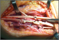
Image-Based Techniques for Percutaneous Iliosacral Screw Start-Site Localization
Iliosacral (SI) screws remain the standard of care for the vast majority of posterior pelvic ring disruptions.1,2 However, despite their routine use, the procedure remains technically demanding with repeated cases of aberrant screw placement and complications.3,4 Sacral morphology is extremely variable within a patient population and affects accurate placement and trajectory of percutaneous screws.5 Classically, it is taught that the external starting position/landmark is at an intersection point of the greater trochanter and the anterior superior iliac spine (ASIS). While this “one size fits all” approach will certainly help to coordinate a start position, it is our experience that multiple stab incisions are necessary to find the optimal start site. To our knowledge, the most common image-based technique used to guide start-point localization and placement of SI screws begins with drawing a virtual sacrum on the patient’s side, guided by the lateral image.5 This article provides a novel image-based technique to be used with, or as a replacement for, the traditional technique.
Techniques
The patient is brought to the operating room and placed supine on a radiolucent operating table. If the closed reduction of the pelvic ring is successful or can be achieved via anterior manipulation/traction, posterior percutaneous pinning is planned. Either a rolled towel or a bag of saline is used as a bolster and placed midline underneath the sacrum and lumbar spine to help “bump” the pelvis and improve the range of motion for the surgeon’s drill. The patient is brought to the edge of the table when possible (ie, a posterior ring injury requiring fixation from only 1 side) to further enhance drill motion. If bilateral screws are planned, surgeons must be careful not to position 1 side at the expense of screw placement on the contralateral side. Nitrous-based anesthetic agents are avoided, because they may collect in the bowel and obscure good radiographic visualization. Arms are placed perpendicular to the body to facilitate the inlet view. Pre-preparation anteroposterior pelvis, inlet, and outlet views are obtained to assure ability to accurately and safely assess landmarks on all projections, and to mark the C-arm position and angles. This process helps decrease “useless” radiographs obtained during the procedure. Acceptable inlet radiographs show the anterior cortex of the S1 body superimposed on the S2 body. Acceptable outlet radiographs show the superior pubic symphysis at the level of the S2 foramen and visualization of the S1/S2 sacral foramen.6 The patient is then prepared in the standard fashion. Reduction maneuvers are performed and, if acceptable alignment is achieved, posterior percutaneous screw placement begins.
Technique 1
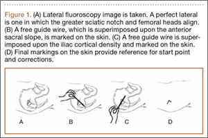
To our knowledge, the most common image-based technique used to guide start-point localization and placement of SI screws begins with drawing a virtual sacrum on the patient’s side using the lateral image. The fluoroscopic machine is set up in a lateral position.5 A free guide wire is superimposed upon the iliac cortical density and anterior sacral slope, which is marked on the skin (Figure 1). The superior portion of S1, as well as the posterior sacral slope, can be marked as well. This process has outlined the sacrum and provides an external landmark for the “safe zone” for screw placement. The operation proceeds in the standard fashion using inlet, outlet, and lateral radiographs. However, the externally drawn sacrum can aid as a reference during guide-pin placement.
Technique 2
This technique takes into account bone anatomy and soft-tissue coverage. It is helpful to think of the abdomen/pelvis as a box. The anterior abdomen represents the top of the box and the lateral buttock represents the side of the box. The corner of the imaginary box is where the abdomen begins to slope down and transitions laterally to become the buttock. This will be referenced as the “down-sloping point” and typically corresponds to the level of the iliac crest (Figure 2).
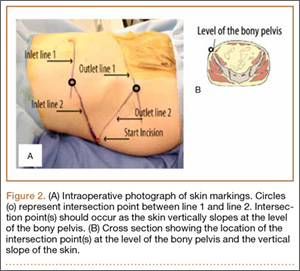
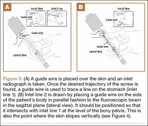
To begin, a standard cannulated screw guide wire is placed flush on the skin of the abdomen. An inlet fluoroscopy image is taken with the guide pin on the abdomen. Imagine that the resulting image represents the planned screw trajectory (Figure 3A). When the position of the guide wire is deemed adequate, a line is marked on the abdomen, using a pen, directly adjacent to the guide wire. This line represents inlet line 1 (Figure 2). The line must continue laterally until the down-sloping point. The sagittal angle of the imaginary inlet fluoroscopic beam is noted, and a guide wire is placed in the same sagittal orientation flush with the skin on the lateral buttock (Figure 3B). The guide wire must be placed so that it intersects with the first line at the down-sloping point. The skin on the lateral aspect of buttock is marked with a second line, which represents inlet line 2 (Figure 2).
The same process is repeated using an outlet view to create outlet lines 1 and 2 (Figures 4A, 4B). At this point there are 4 lines drawn on the patient (Figure 2). A stab incision is made at the intersection of the 2 lines drawn on the lateral buttock; this represents the skin start point, labeled “start incision” (Figure 2). The procedure continues in standard fashion.
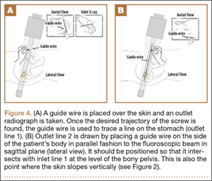
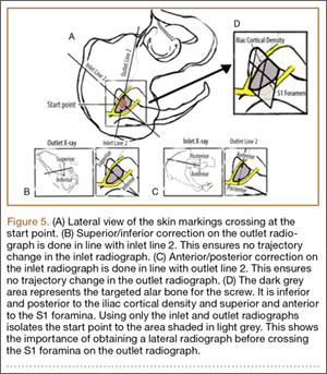
The 4 external reference lines serve multiple purposes. First, the lines mark the true lateral start point for the pin at the level of the skin. This contrasts with the standard technique in which bony landmarks are marked on the skin and the surgeon must estimate a point on the skin that will provide an appropriate trajectory to the bony start point on the ilium. Further, the lines can also be used to reorient the cartesian plane so that adjustments can be isolated to a single plane, ensuring movements only alter the position on a single radiographic view (Figure 5).
Discussion
Despite the widespread use of percutaneous screw placement for posterior pelvic ring injuries, this remains a technically demanding surgery. Recent data suggest patient pelvic anatomy is extremely varied, especially the sacrum.7 Further, screw trajectories vary depending on surgical goals, fracture pattern, and number of screws. Taken together, this implies that there is no perfect universal starting site along the external ilium. Therefore, while classic teaching states to begin screw insertion within the vicinity of the intersection of the greater trochanter and the ASIS, it is our experience that this location is often not ideal.
The inlet, outlet, and lateral radiographs are all vital to assess correct trajectory of the guide pin and drill prior to final screw insertion, but the start site remains a critical step to assure a successful surgical outcome. We present 2 techniques, used together or separately, that allow the surgeon to place the initial guide pin more accurately for percutanous iliosacral screws. Though not specifically examined in this study, we think technique 2 has the potential to save operative time and use less fluoroscopic imaging because a lateral image is not required until later in the case. Technique 2 identifies the start point at the level of the skin. This is in contrast to technique 1, which identifies the desired sacral target and requires a surgeon to select a skin start site that will provide an optimal trajectory towards the desired target. Judging trajectory can be difficult, particularly in obese patients, and technique 2 eliminates this extra variable.
It is also important to consider that criteria-based nonorthogonal imaging is required for percutaneous screw placement. In these cases, it is more difficult to judge trajectory corrections because the fluoroscopic beam cannot guide perpendicular corrections as it can in operations that use orthogonal imaging. Adjustments made perpendicular to the fluoroscopic beam will change trajectory in multiple planes.8 Moreover, because the standard cartesian frame of reference is rotated, understanding the location of the sacrum in space can be especially challenging. When using the first technique, sacral landmarks are delineated, and a virtual sacrum drawn on the patient’s exterior helps with orientation. In the second technique, the ideal pin placement is mapped, and the external reference lines guide uniplanar changes. For example, the line drawn co-planar with the inlet view is essentially marking the sacral slope. Therefore, by following this line, uniplanar changes in the cranial and caudal direction are achieved on the outlet view (Figure 5). Because this line is also in reference to the already known ideal pin placement, ideal pin placement can be maintained in 1 radiographic projection while changing the start site in the appropriate direction. In a similar fashion, the co-planar line identified on the inlet view can be used on the outlet image to affect uniplanar changes in the anteroposterior direction. This technique effectively minimizes disorientation when placing percutaneous SI screws. This can be particularly beneficial when placing screws in the prone position.
Conclusion
We have shown 2 techniques that are routinely used at our institution to help identify an accurate starting position for percutaneous screw placement in posterior pelvic ring injuries. Even experienced traumatologists can more quickly and accurately identify the correct stab incisions leading to more confidently placed screws. Further, we believe understanding the usage of fluoroscopy and the concepts involved in drawing the lines enhance trainees’ comprehension of the complex anatomy of the sacrum.
1. Matta JM, Saucedo T. Internal fixation of pelvic ring fractures. Clin Orthop Relat Res. 1989;242:83-97.
2. Routt ML Jr, Kregor PJ, Simonian PT, Mayo KA. Early results of percutaneous iliosacral screws placed with the patient in the supine position. J Orthop Trauma. 1995;9(3):207-214.
3. Sagi HC, Lindvall EM. Inadvertent intraforaminal iliosacral screw placement despite apparent appropriate positioning on intraoperative fluoroscopy.
J Orthop Trauma. 2005;19(2):130-133.
4. Routt ML Jr, Simonian PT, Mills WJ. Iliosacral screw fixation: early complications of the percutaneous technique. J Orthop Trauma. 1997;11(8):584-589.
5. Routt ML Jr, Simonian PT, Agnew SG, Mann FA. Radiographic recognition of the sacral alar slope for optimal placement of iliosacral screws: a cadaveric and clinical study. J Orthop Trauma. 1996;10(3):171-177.
6. Gardner MJ, Ferrell ED, Nork SE, Segina DN, Routt ML Jr. Percutaneous placement of iliosacral screws without electrodiagnostic monitoring. J Trauma. 2009;66(5):1411-1415.
7. Miller AN, Routt ML Jr. Variations in sacral morphology and implications for iliosacral screw fixation. J Am Acad Orthop Surg. 2012;20(1):8-16.
8. Graves ML, Routt ML. Iliosacral screw placement: are uniplanar changes realistic based on standard fluoroscopic imaging? J Orthop Trauma. 2011;71(1):204-208.
Iliosacral (SI) screws remain the standard of care for the vast majority of posterior pelvic ring disruptions.1,2 However, despite their routine use, the procedure remains technically demanding with repeated cases of aberrant screw placement and complications.3,4 Sacral morphology is extremely variable within a patient population and affects accurate placement and trajectory of percutaneous screws.5 Classically, it is taught that the external starting position/landmark is at an intersection point of the greater trochanter and the anterior superior iliac spine (ASIS). While this “one size fits all” approach will certainly help to coordinate a start position, it is our experience that multiple stab incisions are necessary to find the optimal start site. To our knowledge, the most common image-based technique used to guide start-point localization and placement of SI screws begins with drawing a virtual sacrum on the patient’s side, guided by the lateral image.5 This article provides a novel image-based technique to be used with, or as a replacement for, the traditional technique.
Techniques
The patient is brought to the operating room and placed supine on a radiolucent operating table. If the closed reduction of the pelvic ring is successful or can be achieved via anterior manipulation/traction, posterior percutaneous pinning is planned. Either a rolled towel or a bag of saline is used as a bolster and placed midline underneath the sacrum and lumbar spine to help “bump” the pelvis and improve the range of motion for the surgeon’s drill. The patient is brought to the edge of the table when possible (ie, a posterior ring injury requiring fixation from only 1 side) to further enhance drill motion. If bilateral screws are planned, surgeons must be careful not to position 1 side at the expense of screw placement on the contralateral side. Nitrous-based anesthetic agents are avoided, because they may collect in the bowel and obscure good radiographic visualization. Arms are placed perpendicular to the body to facilitate the inlet view. Pre-preparation anteroposterior pelvis, inlet, and outlet views are obtained to assure ability to accurately and safely assess landmarks on all projections, and to mark the C-arm position and angles. This process helps decrease “useless” radiographs obtained during the procedure. Acceptable inlet radiographs show the anterior cortex of the S1 body superimposed on the S2 body. Acceptable outlet radiographs show the superior pubic symphysis at the level of the S2 foramen and visualization of the S1/S2 sacral foramen.6 The patient is then prepared in the standard fashion. Reduction maneuvers are performed and, if acceptable alignment is achieved, posterior percutaneous screw placement begins.
Technique 1
To our knowledge, the most common image-based technique used to guide start-point localization and placement of SI screws begins with drawing a virtual sacrum on the patient’s side using the lateral image. The fluoroscopic machine is set up in a lateral position.5 A free guide wire is superimposed upon the iliac cortical density and anterior sacral slope, which is marked on the skin (Figure 1). The superior portion of S1, as well as the posterior sacral slope, can be marked as well. This process has outlined the sacrum and provides an external landmark for the “safe zone” for screw placement. The operation proceeds in the standard fashion using inlet, outlet, and lateral radiographs. However, the externally drawn sacrum can aid as a reference during guide-pin placement.
Technique 2
This technique takes into account bone anatomy and soft-tissue coverage. It is helpful to think of the abdomen/pelvis as a box. The anterior abdomen represents the top of the box and the lateral buttock represents the side of the box. The corner of the imaginary box is where the abdomen begins to slope down and transitions laterally to become the buttock. This will be referenced as the “down-sloping point” and typically corresponds to the level of the iliac crest (Figure 2).
To begin, a standard cannulated screw guide wire is placed flush on the skin of the abdomen. An inlet fluoroscopy image is taken with the guide pin on the abdomen. Imagine that the resulting image represents the planned screw trajectory (Figure 3A). When the position of the guide wire is deemed adequate, a line is marked on the abdomen, using a pen, directly adjacent to the guide wire. This line represents inlet line 1 (Figure 2). The line must continue laterally until the down-sloping point. The sagittal angle of the imaginary inlet fluoroscopic beam is noted, and a guide wire is placed in the same sagittal orientation flush with the skin on the lateral buttock (Figure 3B). The guide wire must be placed so that it intersects with the first line at the down-sloping point. The skin on the lateral aspect of buttock is marked with a second line, which represents inlet line 2 (Figure 2).
The same process is repeated using an outlet view to create outlet lines 1 and 2 (Figures 4A, 4B). At this point there are 4 lines drawn on the patient (Figure 2). A stab incision is made at the intersection of the 2 lines drawn on the lateral buttock; this represents the skin start point, labeled “start incision” (Figure 2). The procedure continues in standard fashion.
The 4 external reference lines serve multiple purposes. First, the lines mark the true lateral start point for the pin at the level of the skin. This contrasts with the standard technique in which bony landmarks are marked on the skin and the surgeon must estimate a point on the skin that will provide an appropriate trajectory to the bony start point on the ilium. Further, the lines can also be used to reorient the cartesian plane so that adjustments can be isolated to a single plane, ensuring movements only alter the position on a single radiographic view (Figure 5).
Discussion
Despite the widespread use of percutaneous screw placement for posterior pelvic ring injuries, this remains a technically demanding surgery. Recent data suggest patient pelvic anatomy is extremely varied, especially the sacrum.7 Further, screw trajectories vary depending on surgical goals, fracture pattern, and number of screws. Taken together, this implies that there is no perfect universal starting site along the external ilium. Therefore, while classic teaching states to begin screw insertion within the vicinity of the intersection of the greater trochanter and the ASIS, it is our experience that this location is often not ideal.
The inlet, outlet, and lateral radiographs are all vital to assess correct trajectory of the guide pin and drill prior to final screw insertion, but the start site remains a critical step to assure a successful surgical outcome. We present 2 techniques, used together or separately, that allow the surgeon to place the initial guide pin more accurately for percutanous iliosacral screws. Though not specifically examined in this study, we think technique 2 has the potential to save operative time and use less fluoroscopic imaging because a lateral image is not required until later in the case. Technique 2 identifies the start point at the level of the skin. This is in contrast to technique 1, which identifies the desired sacral target and requires a surgeon to select a skin start site that will provide an optimal trajectory towards the desired target. Judging trajectory can be difficult, particularly in obese patients, and technique 2 eliminates this extra variable.
It is also important to consider that criteria-based nonorthogonal imaging is required for percutaneous screw placement. In these cases, it is more difficult to judge trajectory corrections because the fluoroscopic beam cannot guide perpendicular corrections as it can in operations that use orthogonal imaging. Adjustments made perpendicular to the fluoroscopic beam will change trajectory in multiple planes.8 Moreover, because the standard cartesian frame of reference is rotated, understanding the location of the sacrum in space can be especially challenging. When using the first technique, sacral landmarks are delineated, and a virtual sacrum drawn on the patient’s exterior helps with orientation. In the second technique, the ideal pin placement is mapped, and the external reference lines guide uniplanar changes. For example, the line drawn co-planar with the inlet view is essentially marking the sacral slope. Therefore, by following this line, uniplanar changes in the cranial and caudal direction are achieved on the outlet view (Figure 5). Because this line is also in reference to the already known ideal pin placement, ideal pin placement can be maintained in 1 radiographic projection while changing the start site in the appropriate direction. In a similar fashion, the co-planar line identified on the inlet view can be used on the outlet image to affect uniplanar changes in the anteroposterior direction. This technique effectively minimizes disorientation when placing percutaneous SI screws. This can be particularly beneficial when placing screws in the prone position.
Conclusion
We have shown 2 techniques that are routinely used at our institution to help identify an accurate starting position for percutaneous screw placement in posterior pelvic ring injuries. Even experienced traumatologists can more quickly and accurately identify the correct stab incisions leading to more confidently placed screws. Further, we believe understanding the usage of fluoroscopy and the concepts involved in drawing the lines enhance trainees’ comprehension of the complex anatomy of the sacrum.
1. Matta JM, Saucedo T. Internal fixation of pelvic ring fractures. Clin Orthop Relat Res. 1989;242:83-97.
2. Routt ML Jr, Kregor PJ, Simonian PT, Mayo KA. Early results of percutaneous iliosacral screws placed with the patient in the supine position. J Orthop Trauma. 1995;9(3):207-214.
3. Sagi HC, Lindvall EM. Inadvertent intraforaminal iliosacral screw placement despite apparent appropriate positioning on intraoperative fluoroscopy.
J Orthop Trauma. 2005;19(2):130-133.
4. Routt ML Jr, Simonian PT, Mills WJ. Iliosacral screw fixation: early complications of the percutaneous technique. J Orthop Trauma. 1997;11(8):584-589.
5. Routt ML Jr, Simonian PT, Agnew SG, Mann FA. Radiographic recognition of the sacral alar slope for optimal placement of iliosacral screws: a cadaveric and clinical study. J Orthop Trauma. 1996;10(3):171-177.
6. Gardner MJ, Ferrell ED, Nork SE, Segina DN, Routt ML Jr. Percutaneous placement of iliosacral screws without electrodiagnostic monitoring. J Trauma. 2009;66(5):1411-1415.
7. Miller AN, Routt ML Jr. Variations in sacral morphology and implications for iliosacral screw fixation. J Am Acad Orthop Surg. 2012;20(1):8-16.
8. Graves ML, Routt ML. Iliosacral screw placement: are uniplanar changes realistic based on standard fluoroscopic imaging? J Orthop Trauma. 2011;71(1):204-208.
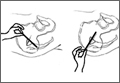
Emergency Imaging
Case
A 32-year-old woman presented to the ED with a 6-month history of worsening skin erosion along her right elbow and forearm. The patient described unremitting pain and progressive shortening of her forearm. Radiographs were obtained; representative images are shown above (Figures 1a and 1b).
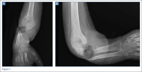
What is the diagnosis?
***BREAKING***
Answer
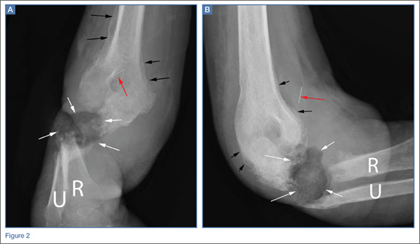
Anteroposterior and lateral radiographs of the right elbow demonstrated a large soft tissue defect involving the proximal forearm (white arrows, Figures 2a and 2b) with extensive osseous destruction of the proximal radius (R) and ulna (U). Deformity of the forearm was apparent. There was marked periosteal reaction involving the distal humerus (black arrows, Figures 2a and 2b). A needle fragment projected over the antecubital space on both radiographs (red arrow, Figures 2a and 2b). These findings indicated the presence of osteomyelitis and septic arthritis. The needle fragment suggested drug abuse as the likely etiology.
This patient had a 2-year history of intravenous (IV) drug abuse. She initially noticed an open wound on her elbow about 6 months prior to presentation. As the wound worsened, she developed increasing pain, numbness, and weakness in her forearm and hand. Physical examination revealed a markedly contracted forearm. There was a large, deep ulcer at the lateral aspect of the elbow and proximal forearm, with exposed bone and surrounding necrotic tissue. Motor function was limited to minimal movement of the thumb and index finger, and there was complete loss of sensation in an ulnar distribution. A deep tissue culture grew methicillin-resistant Staphylococcus aureus, and a bone biopsy confirmed the diagnosis of osteomyelitis. The patient was treated with antibiotics but ultimately required transhumeral amputation.
Intravenous drug users are at risk for soft tissue and bone complications, including ulcer, abscess, septic bursitis, tenosynovitis, cellulitis, necrotizing fasciitis, septic arthritis, and osteomyelitis.1 Osteomyelitis can arise from direct inoculation, hematogenous spread, or, as was the case in this patient, secondary to seeding from a contiguous soft tissue infection.2 Unlike hematogenous osteomyelitis, contiguous focus osteomyelitis is often polymicrobial.
Radiographs are not sensitive for osteomyelitis, particularly early in the process, but may reveal loss of soft tissue planes prior to the development of focal osteopenia and osseous destruction.3 In this case, the diagnosis could be made through radiography given the marked osseous destruction, periosteal reaction, and soft tissue ulceration. However, in presentations in which there is a continued clinical suspicion for osteomyelitis despite normal or inconclusive radiographs, magnetic resonance imaging (MRI) with contrast is the preferred examination for further evaluation. While both contrast and noncontrast-enhanced MRI may show the bone marrow edema related to osteomyelitis, contrast is helpful in evaluating for soft tissue abscesses and in determining if there is an adequate blood supply for IV treatment to be effective. An alternative exam to MRI would be nuclear scintigraphy (a tagged, white blood cell scan and/or a three-phase bone scan).
Later in the disease course, periosteal bone reaction and sclerotic reactive bone formation can be seen. A sequestrum forms when there is complete resorption of the bone adjacent to a devitalized segment of infected bone, leaving the isolated devitalized segment to function as a nidus for continued infection.3
Dr Spivey is a resident in the department of radiology at New York Presbyterian Hospital/Weill Cornell Medical College in New York City. Dr Bartolotta is an assistant professor of radiology at Weill Cornell Medical College in New York City and assistant attending radiologist at New York-Presbyterian Hospital/Weill Cornell Medical Center. Dr Hentel is an associate professor of clinical radiology at Weill Cornell Medical College in New York City. He is also chief of emergency/musculoskeletal imaging and executive vice-chairman for the department of radiology at New York-Presbyterian Hospital/Weill Cornell Medical Center; and associate editor, imaging, of the EMERGENCY MEDICINE editorial board.
- Theodorou SJ, Theodorou DJ, Resnick D. Imaging findings of complications affecting the upper extremity in intravenous drug users: featured cases. Emerg Radiol. 2008;15(4):227-239.
- Sia IG, Berbari, EF. Infection and musculoskeletal conditions: Osteomyelitis. Best Pract Res Clin Rheumatol. 2006;20(6):1065-1081.
- Gold RH, Hawkins RA, Katz RD. Bacterial osteomyelitis: findings on plain radiography, CT, MR, and scintigraphy. AJR Am J Roentgenol. 1991;157(2):365-370.
Case
A 32-year-old woman presented to the ED with a 6-month history of worsening skin erosion along her right elbow and forearm. The patient described unremitting pain and progressive shortening of her forearm. Radiographs were obtained; representative images are shown above (Figures 1a and 1b).
What is the diagnosis?
***BREAKING***
Answer
Anteroposterior and lateral radiographs of the right elbow demonstrated a large soft tissue defect involving the proximal forearm (white arrows, Figures 2a and 2b) with extensive osseous destruction of the proximal radius (R) and ulna (U). Deformity of the forearm was apparent. There was marked periosteal reaction involving the distal humerus (black arrows, Figures 2a and 2b). A needle fragment projected over the antecubital space on both radiographs (red arrow, Figures 2a and 2b). These findings indicated the presence of osteomyelitis and septic arthritis. The needle fragment suggested drug abuse as the likely etiology.
This patient had a 2-year history of intravenous (IV) drug abuse. She initially noticed an open wound on her elbow about 6 months prior to presentation. As the wound worsened, she developed increasing pain, numbness, and weakness in her forearm and hand. Physical examination revealed a markedly contracted forearm. There was a large, deep ulcer at the lateral aspect of the elbow and proximal forearm, with exposed bone and surrounding necrotic tissue. Motor function was limited to minimal movement of the thumb and index finger, and there was complete loss of sensation in an ulnar distribution. A deep tissue culture grew methicillin-resistant Staphylococcus aureus, and a bone biopsy confirmed the diagnosis of osteomyelitis. The patient was treated with antibiotics but ultimately required transhumeral amputation.
Intravenous drug users are at risk for soft tissue and bone complications, including ulcer, abscess, septic bursitis, tenosynovitis, cellulitis, necrotizing fasciitis, septic arthritis, and osteomyelitis.1 Osteomyelitis can arise from direct inoculation, hematogenous spread, or, as was the case in this patient, secondary to seeding from a contiguous soft tissue infection.2 Unlike hematogenous osteomyelitis, contiguous focus osteomyelitis is often polymicrobial.
Radiographs are not sensitive for osteomyelitis, particularly early in the process, but may reveal loss of soft tissue planes prior to the development of focal osteopenia and osseous destruction.3 In this case, the diagnosis could be made through radiography given the marked osseous destruction, periosteal reaction, and soft tissue ulceration. However, in presentations in which there is a continued clinical suspicion for osteomyelitis despite normal or inconclusive radiographs, magnetic resonance imaging (MRI) with contrast is the preferred examination for further evaluation. While both contrast and noncontrast-enhanced MRI may show the bone marrow edema related to osteomyelitis, contrast is helpful in evaluating for soft tissue abscesses and in determining if there is an adequate blood supply for IV treatment to be effective. An alternative exam to MRI would be nuclear scintigraphy (a tagged, white blood cell scan and/or a three-phase bone scan).
Later in the disease course, periosteal bone reaction and sclerotic reactive bone formation can be seen. A sequestrum forms when there is complete resorption of the bone adjacent to a devitalized segment of infected bone, leaving the isolated devitalized segment to function as a nidus for continued infection.3
Dr Spivey is a resident in the department of radiology at New York Presbyterian Hospital/Weill Cornell Medical College in New York City. Dr Bartolotta is an assistant professor of radiology at Weill Cornell Medical College in New York City and assistant attending radiologist at New York-Presbyterian Hospital/Weill Cornell Medical Center. Dr Hentel is an associate professor of clinical radiology at Weill Cornell Medical College in New York City. He is also chief of emergency/musculoskeletal imaging and executive vice-chairman for the department of radiology at New York-Presbyterian Hospital/Weill Cornell Medical Center; and associate editor, imaging, of the EMERGENCY MEDICINE editorial board.
- Theodorou SJ, Theodorou DJ, Resnick D. Imaging findings of complications affecting the upper extremity in intravenous drug users: featured cases. Emerg Radiol. 2008;15(4):227-239.
- Sia IG, Berbari, EF. Infection and musculoskeletal conditions: Osteomyelitis. Best Pract Res Clin Rheumatol. 2006;20(6):1065-1081.
- Gold RH, Hawkins RA, Katz RD. Bacterial osteomyelitis: findings on plain radiography, CT, MR, and scintigraphy. AJR Am J Roentgenol. 1991;157(2):365-370.
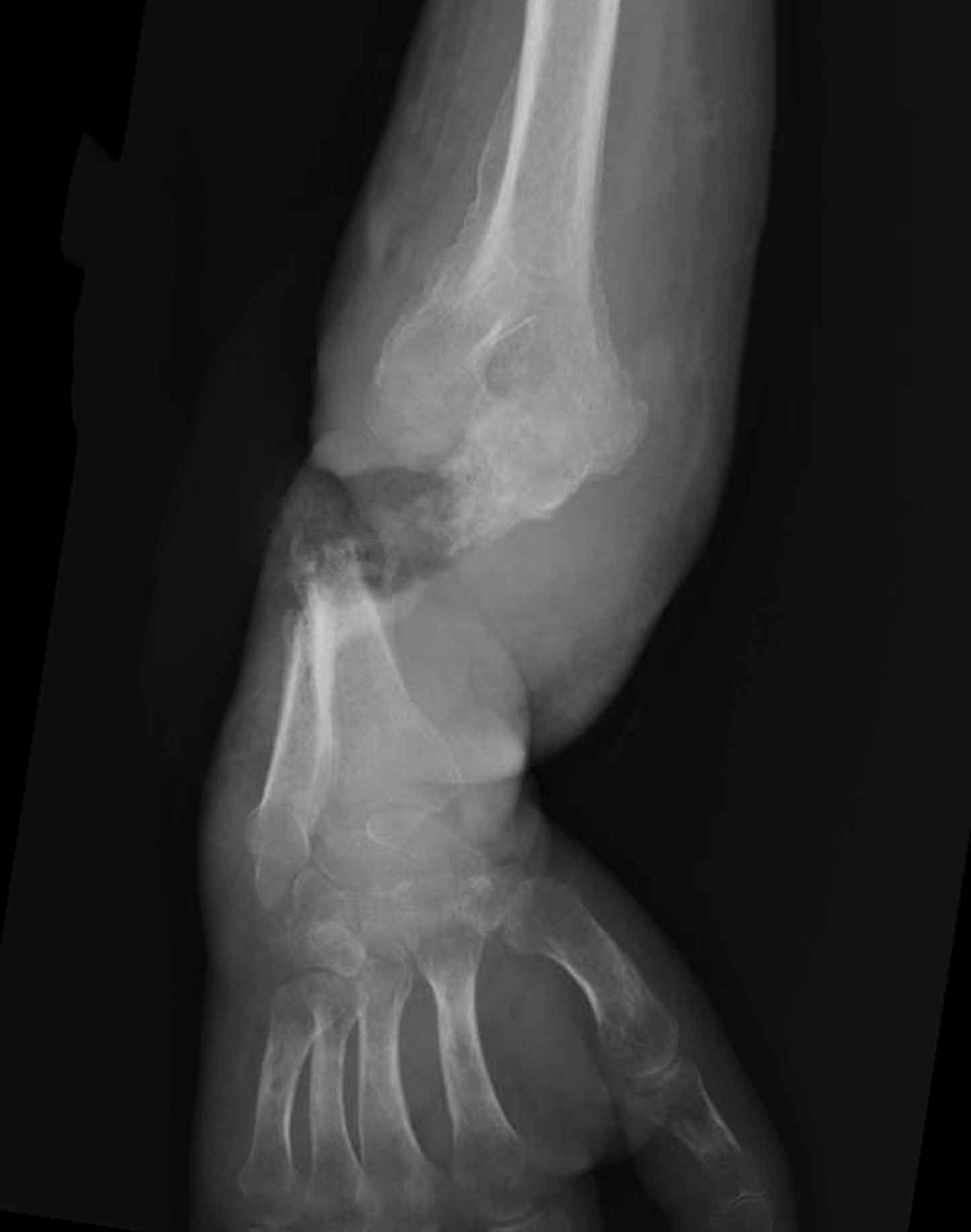
An unusual cause of vitamin B12 and iron deficiency
A 76-year-old woman visiting from Ethiopia presented for further evaluation of concomitant iron and vitamin B12 deficiency anemia that had developed over the previous 6 months. During that time, she had complained of ongoing fatigue and increasing paresthesias in the hands and feet.
At presentation, her hemoglobin concentration was 7.8 g/dL (reference range 11.5–15), with a mean corpuscular volume of 81.8 fL (81.5–97.0). These values were down from her baseline hemoglobin of 12 g/dL and corpuscular volume of 85.8 recorded more than 1 year ago. Serum studies showed an iron concentration of 21 µg/dL (37–170), ferritin 3 ng/mL (10–107), and percent saturation of transferrin 5% (20%–55%). Also noted was a low vitamin B12 level of 108 pg/mL (180–1,241 pg/mL). She had no overt signs of gastrointestinal blood loss. She did not report altered bowel habits or use of nonsteroidal anti-inflammatory medications.
Given her country of origin, she was sent for initial stool testing for ova and parasites, which was unrevealing.
She underwent esophagogastroduodenoscopy and colonoscopy, which revealed no underlying cause of her iron deficiency or vitamin B12 insufficiency. But further evaluation with capsule endoscopy showed evidence of a tapeworm in the distal duodenum (Figure 1).
She was given praziquantel in a single oral dose of 10 mg/kg. Repeat stool culture 1 month later showed no evidence of tapeworm infection, and at follow-up 3 months later, her hemoglobin had recovered to 13.2 g/dL with a corpuscular volume of 87.6 fL and no residual vitamin B12 or iron deficiency. She reported complete resolution of fatigue and of paresthesias of the hands and feet.
DIPHYLLOBOTHRIUM LATUM
The appearance on capsule endoscopy indicated Diphyllobothrium latum as the likely parasite. This tapeworm is acquired by ingesting undercooked or raw fish. Infection is most common in Northern Europe but has been reported in Africa.1
As it grows, the tapeworm develops chains of segments and can reach a length of 1 to 15 meters.1 In humans, it typically resides in the small intestine. Most patients are asymptomatic or have moderate nonspecific symptoms such as abdominal pain and diarrhea. A key differentiating aspect of D latum infection is vitamin B12 deficiency caused by consumption of the vitamin by the parasite, as well as by parasite-mediated dissociation of the vitamin B12-intrinsic factor complex, thus making the vitamin unavailable to the host.
Up to 40% of people infected with D latum develop low levels of vitamin B12, and 2% develop symptomatic megaloblastic anemia.2 Iron deficiency anemia is uncommon but has been reported.3 In our patient, the concomitant iron deficiency was probably secondary to involvement of the duodenum, where a significant amount of dietary iron is absorbed.
The diagnosis is typically established by stool testing for ova and parasites. When stool samples do not reveal a cause of the symptoms, as in this patient, endoscopy can be used. Capsule endoscopy has not been widely used in the diagnosis of intestinal helminth infection, although reports exist describing the use of capsule endoscopy to detect intestinal parasites. Notably, as in this case, intestinal parasite infection is occasionally found during investigations of anemia and vitamin deficiencies of unknown cause.4
As in our patient, treatment of infection with this species of tapeworm typically involves a single oral dose of praziquantel; this off-label use has been shown to lead to resolution of symptoms in nearly all patients treated.5
- Schantz PM. Tapeworms (cestodiasis). Gastroenterol Clin North Am 1996; 25:637–653.
- Scholz T, Garcia HH, Kuchta R, Wicht B. Update on the human broad tapeworm (genus Diphyllobothrium), including clinical relevance. Clin Microbiol Rev 2009; 22:146–160,
- Stanciu C, Trifan A, Singeap AM, Sfarti C, Cojocariu C, Luca M. Diphyllobothrium latum identified by capsule endoscopy—an unusual cause of iron-deficiency anemia. J Gastrointestin Liver Dis 2009; 18:142.
- Soga K, Handa O, Yamada M, et al. In vivo imaging of intestinal helminths by capsule endoscopy. Parasitol Int 2014; 63:221–228.
- Drugs for Parasitic Infections. 3rd edition. Treatment guidelines from the Medical Letter 2010. The Medical Letter, Inc., New Rochelle, NY.
A 76-year-old woman visiting from Ethiopia presented for further evaluation of concomitant iron and vitamin B12 deficiency anemia that had developed over the previous 6 months. During that time, she had complained of ongoing fatigue and increasing paresthesias in the hands and feet.
At presentation, her hemoglobin concentration was 7.8 g/dL (reference range 11.5–15), with a mean corpuscular volume of 81.8 fL (81.5–97.0). These values were down from her baseline hemoglobin of 12 g/dL and corpuscular volume of 85.8 recorded more than 1 year ago. Serum studies showed an iron concentration of 21 µg/dL (37–170), ferritin 3 ng/mL (10–107), and percent saturation of transferrin 5% (20%–55%). Also noted was a low vitamin B12 level of 108 pg/mL (180–1,241 pg/mL). She had no overt signs of gastrointestinal blood loss. She did not report altered bowel habits or use of nonsteroidal anti-inflammatory medications.
Given her country of origin, she was sent for initial stool testing for ova and parasites, which was unrevealing.
She underwent esophagogastroduodenoscopy and colonoscopy, which revealed no underlying cause of her iron deficiency or vitamin B12 insufficiency. But further evaluation with capsule endoscopy showed evidence of a tapeworm in the distal duodenum (Figure 1).
She was given praziquantel in a single oral dose of 10 mg/kg. Repeat stool culture 1 month later showed no evidence of tapeworm infection, and at follow-up 3 months later, her hemoglobin had recovered to 13.2 g/dL with a corpuscular volume of 87.6 fL and no residual vitamin B12 or iron deficiency. She reported complete resolution of fatigue and of paresthesias of the hands and feet.
DIPHYLLOBOTHRIUM LATUM
The appearance on capsule endoscopy indicated Diphyllobothrium latum as the likely parasite. This tapeworm is acquired by ingesting undercooked or raw fish. Infection is most common in Northern Europe but has been reported in Africa.1
As it grows, the tapeworm develops chains of segments and can reach a length of 1 to 15 meters.1 In humans, it typically resides in the small intestine. Most patients are asymptomatic or have moderate nonspecific symptoms such as abdominal pain and diarrhea. A key differentiating aspect of D latum infection is vitamin B12 deficiency caused by consumption of the vitamin by the parasite, as well as by parasite-mediated dissociation of the vitamin B12-intrinsic factor complex, thus making the vitamin unavailable to the host.
Up to 40% of people infected with D latum develop low levels of vitamin B12, and 2% develop symptomatic megaloblastic anemia.2 Iron deficiency anemia is uncommon but has been reported.3 In our patient, the concomitant iron deficiency was probably secondary to involvement of the duodenum, where a significant amount of dietary iron is absorbed.
The diagnosis is typically established by stool testing for ova and parasites. When stool samples do not reveal a cause of the symptoms, as in this patient, endoscopy can be used. Capsule endoscopy has not been widely used in the diagnosis of intestinal helminth infection, although reports exist describing the use of capsule endoscopy to detect intestinal parasites. Notably, as in this case, intestinal parasite infection is occasionally found during investigations of anemia and vitamin deficiencies of unknown cause.4
As in our patient, treatment of infection with this species of tapeworm typically involves a single oral dose of praziquantel; this off-label use has been shown to lead to resolution of symptoms in nearly all patients treated.5
- Schantz PM. Tapeworms (cestodiasis). Gastroenterol Clin North Am 1996; 25:637–653.
- Scholz T, Garcia HH, Kuchta R, Wicht B. Update on the human broad tapeworm (genus Diphyllobothrium), including clinical relevance. Clin Microbiol Rev 2009; 22:146–160,
- Stanciu C, Trifan A, Singeap AM, Sfarti C, Cojocariu C, Luca M. Diphyllobothrium latum identified by capsule endoscopy—an unusual cause of iron-deficiency anemia. J Gastrointestin Liver Dis 2009; 18:142.
- Soga K, Handa O, Yamada M, et al. In vivo imaging of intestinal helminths by capsule endoscopy. Parasitol Int 2014; 63:221–228.
- Drugs for Parasitic Infections. 3rd edition. Treatment guidelines from the Medical Letter 2010. The Medical Letter, Inc., New Rochelle, NY.
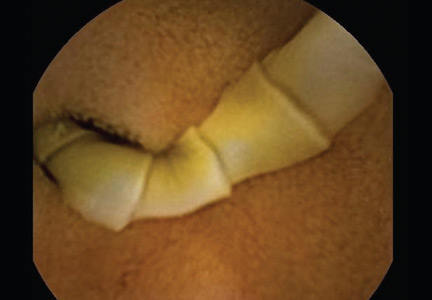
SAEM: Pelvic CT may not be needed to diagnose intra-abdominal injury in children
SAN DIEGO – Children who have suffered blunt trauma are routinely screened in emergency departments for intra-abdominal injury via computed tomography of the abdomen and pelvis.
But concerns about excess exposure to CT radiation, particularly to the gonads, led one group of researchers to question whether it’s necessary to scan the entire abdominopelvic region in all of these patients to identify intra-abdominal injury (IAI).

Dr. Stacy Reynolds and her colleagues at the Carolinas Medical Center in Charlotte, N.C., hypothesized that CT limited to the radiographic abdomen – the region between the dome of the diaphragm to the top of the iliac crest – can capture the vast majority of IAIs in this population.
At the Society for Academic Emergency Medicine annual meeting, Dr. Reynolds presented results from a retrospective cohort study enrolling 313 hemodynamically stable pediatric patients (median age 14 years, 64% male) presenting to 12 EDs after blunt trauma. Patients with known pelvic fractures or hip dislocation were excluded, as they would have had a clear indication for a full abdominopelvic CT.
All subjects underwent axial abdominopelvic CT imaging. Researchers created matched pairs of images comprising the original scans and those that had been altered with software that truncated the pelvic portion of the study to create CT abdomen-only studies. Study radiologists were blinded to the results of the original scans.
Twenty-six IAI’s were diagnosed in 24 patients: 8 hepatic injuries, 12 splenic injuries, 5 renal injuries, and 1 retroperitoneal hemorrhage. Abdominal CT alone was 85% sensitive (95% confidence interval, 65%-96%) and 99% specific (95% CI, 97%-100%) in identifying IAIs. The four missed injuries were solid organ injuries within the radiographic abdomen. False positives occurred in two of the complete scans, both involving free fluid prompting suspicion of small bowel injury later ruled out by clinical observation.
Dr. Reynolds said in an interview said that the findings, while promising, were limited by the study’s small numbers, and its use of axial images alone, when sagittal images also would be required for the most accurate diagnoses. Also, physician suspicion of IAI prior to imaging was not captured because of the study’s retrospective design, she said. “The real key to whether or not this hypothesis is valuable is if physicians are able to target the right population of patients for application.”
Dr. Reynolds cautioned that the findings would need to be validated in a larger trial before any changes could be made to clinical practice. “Some of the outcomes that we need to make sure whether we’re missing are still rare,” she said. “You couldn’t feel confident that this is the right way to go with a study this small, but it establishes that we can safely and ethically pursue a multicenter trial that would examine the issue with bigger numbers.”
Other groups of investigators, including members of the Pediatric Emergency Care Applied Research Network (PECARN), also have taken up the question of identifying children at low risk of IAI who may not need CT screening after blunt trauma. In 2013, PECARN published a prediction rule using only patient history and physical examination findings intended to obviate use of CT in the lowest-risk patients (Ann. Emerg. Med. 2013;62:107-16.e2).
Dr. Reynolds said that while overuse of CT was a worrisome trend that could have long-term implications for patients, and that it was important to identify ways it might be limited, there is a reason it remains the go-to technology in the ED for detecting IAI. “It’s got very high sensitivity and specificity. If you’re a busy trauma surgeon who’s admitting 20 injured patients in a night, there’s no faster or more efficient way to determine whether the patient in front of you is injured.”
The study was funded by the Carolinas Trauma Network Research Center of Excellence. None of the investigators disclosed conflicts of interest.
SAN DIEGO – Children who have suffered blunt trauma are routinely screened in emergency departments for intra-abdominal injury via computed tomography of the abdomen and pelvis.
But concerns about excess exposure to CT radiation, particularly to the gonads, led one group of researchers to question whether it’s necessary to scan the entire abdominopelvic region in all of these patients to identify intra-abdominal injury (IAI).
Dr. Stacy Reynolds and her colleagues at the Carolinas Medical Center in Charlotte, N.C., hypothesized that CT limited to the radiographic abdomen – the region between the dome of the diaphragm to the top of the iliac crest – can capture the vast majority of IAIs in this population.
At the Society for Academic Emergency Medicine annual meeting, Dr. Reynolds presented results from a retrospective cohort study enrolling 313 hemodynamically stable pediatric patients (median age 14 years, 64% male) presenting to 12 EDs after blunt trauma. Patients with known pelvic fractures or hip dislocation were excluded, as they would have had a clear indication for a full abdominopelvic CT.
All subjects underwent axial abdominopelvic CT imaging. Researchers created matched pairs of images comprising the original scans and those that had been altered with software that truncated the pelvic portion of the study to create CT abdomen-only studies. Study radiologists were blinded to the results of the original scans.
Twenty-six IAI’s were diagnosed in 24 patients: 8 hepatic injuries, 12 splenic injuries, 5 renal injuries, and 1 retroperitoneal hemorrhage. Abdominal CT alone was 85% sensitive (95% confidence interval, 65%-96%) and 99% specific (95% CI, 97%-100%) in identifying IAIs. The four missed injuries were solid organ injuries within the radiographic abdomen. False positives occurred in two of the complete scans, both involving free fluid prompting suspicion of small bowel injury later ruled out by clinical observation.
Dr. Reynolds said in an interview said that the findings, while promising, were limited by the study’s small numbers, and its use of axial images alone, when sagittal images also would be required for the most accurate diagnoses. Also, physician suspicion of IAI prior to imaging was not captured because of the study’s retrospective design, she said. “The real key to whether or not this hypothesis is valuable is if physicians are able to target the right population of patients for application.”
Dr. Reynolds cautioned that the findings would need to be validated in a larger trial before any changes could be made to clinical practice. “Some of the outcomes that we need to make sure whether we’re missing are still rare,” she said. “You couldn’t feel confident that this is the right way to go with a study this small, but it establishes that we can safely and ethically pursue a multicenter trial that would examine the issue with bigger numbers.”
Other groups of investigators, including members of the Pediatric Emergency Care Applied Research Network (PECARN), also have taken up the question of identifying children at low risk of IAI who may not need CT screening after blunt trauma. In 2013, PECARN published a prediction rule using only patient history and physical examination findings intended to obviate use of CT in the lowest-risk patients (Ann. Emerg. Med. 2013;62:107-16.e2).
Dr. Reynolds said that while overuse of CT was a worrisome trend that could have long-term implications for patients, and that it was important to identify ways it might be limited, there is a reason it remains the go-to technology in the ED for detecting IAI. “It’s got very high sensitivity and specificity. If you’re a busy trauma surgeon who’s admitting 20 injured patients in a night, there’s no faster or more efficient way to determine whether the patient in front of you is injured.”
The study was funded by the Carolinas Trauma Network Research Center of Excellence. None of the investigators disclosed conflicts of interest.
FROM SAEM 2015
Key clinical point: Abdominal CT scans without a pelvic portion may diagnose intra-abdominal injury in children as well as do full abdominopelvic scans, with less radiation exposure to patients.
Major finding: Abdominal CT alone was 85% sensitive (95% CI, 65%-96%) and 99% specific (95% CI, 97%-100%) in identifying IAIs. The four missed injuries were solid organ injuries within the radiographic abdomen.
Data source: A retrospective cohort study of 313 patients aged 3-17 years presenting to 12 emergency departments.
Disclosures: The study was funded by the Carolinas Trauma Network Research Center of Excellence. None of the investigators disclosed conflicts of interest.

Two different MRI-safe ICDs show safety, efficacy
BOSTON – An implantable cardioverter defibrillator device that can safely undergo magnetic resonance imaging may soon be a commercial reality as two different models from two different manufacturers showed safety and mostly uncompromised efficacy during and after MRI in two separate studies reported at the annual scientific sessions of the Heart Rhythm Society.
The impending availability of two different brands of implantable cardioverter defibrillators (ICDs) that allow patients to safely undergo MRI “will hopefully open a new era when most [ICDs] are designed” to be MRI safe, said Dr. Khaled A. Awad, an electrophysiologist at the University of Alabama at Birmingham, and lead investigator for one of the new studies.
“Within 10 years, all ICDs getting implanted will be MRI compatible,” predicted Dr. Michael R. Gold, chief of cardiology and medical director of the heart and vascular center at the Medical University of South Carolina in Charleston and lead investigator for the second study.
Until now, having an ICD in a patient created a contraindication for using MRI on the patient, a situation that would change once MRI-safe ICDs become routinely available, noted Dr. Gold. MRI-compatible implanted pacemakers have been on the U.S. market since 2011; ICDs able to safely undergo MRI exposure became the next frontier for creating implanted cardiovascular devices that allow MRIs. Both studies used MRI performed with a 1.5-T magnetic field, a strength commonly used in routine practice today.

The ProMRI study reported by Dr. Awad enrolled patients at 39 U.S. centers who at least 5 weeks previously had received an Iforia ICD made by Biotronik along with commercially available leads believed to be MRI safe. The researchers performed MRIs of the heart or thoracic spine on 154 patients, and then ran follow-up examinations on 150 patients 1 month after the MRI, and a second, 3-month follow-up on 92 of the enrolled patients. The study did not include any control patients who received the ICD and did not undergo MRI.
No patient had an adverse event related or possibly related to their ICD either at the time of the MRI or at follow-up, Dr. Awad reported. In addition, no patients had a significant change in their ICD’s ventricular capture threshold, and one patient had a significant change in the ICD’s ventricular sensing. During follow-up, the ICDs of enrolled patients detected a total of 403 ventricular arrhythmias in 39 patients, with all these episodes appropriately detected and treated.

The study reported by Dr. Gold enrolled patients at 42 centers in 13 countries including the United States. The investigators implanted ICDs into 263 patients using commercially available leads, and then 9-12 weeks after placement, they randomized patients at a 2:1 rate to either undergo MRI or receive no MRI and serve as controls. Of the 175 patients randomized to undergo MRI, 156 actually received the examination, a full-body examination, and 147 participated in follow-up to at least 1 month and were part of the safety analysis.
Patient follow-up showed no complications, no episodes of a significant change in ventricular-pacing sensing threshold, and one episode of a significant change in ventricular-sensing amplitude, Dr. Gold reported, showing safety and efficacy outcomes identical to those in the trial of the Biotronik device. During follow-up 34 episodes of ventricular tachycardia or fibrillation occurred in 24 patients in the MRI group, and the implanted ICDs detected and treated all episodes appropriately. Concurrent with Dr. Gold’s report, the results also appeared in an article published online (J. Am. Coll. Cardiol. 2015 [doi:10.1016/j.jacc.2015.04.047]).
[email protected]
On Twitter @mitchelzoler
MRI-safe implantable cardioverter defibrillators will become the standard of care. They are especially appropriate for patients who are younger when they receive their device and hence more likely to need an MRI at sometime in their future, as well as for older patients who are known to need an MRI in the foreseeable future.

|
Dr. Fred M. Kusumoto |
MRI-safe implanted pacemakers have been routinely available in the United States for a few years, and since their U.S. introduction they have gradually increased their market share and have become the dominant device for younger patients and for patients with a scheduled, upcoming MRI.
Now that MRI-safe pacemakers and implantable cardioverter defibrillators exist, the next step will be to create an MRI-compatible cardiac resynchronization therapy device, but their more complicated design and lead placements will mean further design and engineering challenges.
Dr. Fred M. Kusumoto is a professor of medicine and an electrophysiologist at the Mayo Clinic in Jacksonville, Fla. He had no relevant financial disclosures. He made these comments in an interview.
MRI-safe implantable cardioverter defibrillators will become the standard of care. They are especially appropriate for patients who are younger when they receive their device and hence more likely to need an MRI at sometime in their future, as well as for older patients who are known to need an MRI in the foreseeable future.
|
|
Dr. Fred M. Kusumoto |
MRI-safe implanted pacemakers have been routinely available in the United States for a few years, and since their U.S. introduction they have gradually increased their market share and have become the dominant device for younger patients and for patients with a scheduled, upcoming MRI.
Now that MRI-safe pacemakers and implantable cardioverter defibrillators exist, the next step will be to create an MRI-compatible cardiac resynchronization therapy device, but their more complicated design and lead placements will mean further design and engineering challenges.
Dr. Fred M. Kusumoto is a professor of medicine and an electrophysiologist at the Mayo Clinic in Jacksonville, Fla. He had no relevant financial disclosures. He made these comments in an interview.
BOSTON – An implantable cardioverter defibrillator device that can safely undergo magnetic resonance imaging may soon be a commercial reality as two different models from two different manufacturers showed safety and mostly uncompromised efficacy during and after MRI in two separate studies reported at the annual scientific sessions of the Heart Rhythm Society.
The impending availability of two different brands of implantable cardioverter defibrillators (ICDs) that allow patients to safely undergo MRI “will hopefully open a new era when most [ICDs] are designed” to be MRI safe, said Dr. Khaled A. Awad, an electrophysiologist at the University of Alabama at Birmingham, and lead investigator for one of the new studies.
“Within 10 years, all ICDs getting implanted will be MRI compatible,” predicted Dr. Michael R. Gold, chief of cardiology and medical director of the heart and vascular center at the Medical University of South Carolina in Charleston and lead investigator for the second study.
Until now, having an ICD in a patient created a contraindication for using MRI on the patient, a situation that would change once MRI-safe ICDs become routinely available, noted Dr. Gold. MRI-compatible implanted pacemakers have been on the U.S. market since 2011; ICDs able to safely undergo MRI exposure became the next frontier for creating implanted cardiovascular devices that allow MRIs. Both studies used MRI performed with a 1.5-T magnetic field, a strength commonly used in routine practice today.
The ProMRI study reported by Dr. Awad enrolled patients at 39 U.S. centers who at least 5 weeks previously had received an Iforia ICD made by Biotronik along with commercially available leads believed to be MRI safe. The researchers performed MRIs of the heart or thoracic spine on 154 patients, and then ran follow-up examinations on 150 patients 1 month after the MRI, and a second, 3-month follow-up on 92 of the enrolled patients. The study did not include any control patients who received the ICD and did not undergo MRI.
No patient had an adverse event related or possibly related to their ICD either at the time of the MRI or at follow-up, Dr. Awad reported. In addition, no patients had a significant change in their ICD’s ventricular capture threshold, and one patient had a significant change in the ICD’s ventricular sensing. During follow-up, the ICDs of enrolled patients detected a total of 403 ventricular arrhythmias in 39 patients, with all these episodes appropriately detected and treated.
The study reported by Dr. Gold enrolled patients at 42 centers in 13 countries including the United States. The investigators implanted ICDs into 263 patients using commercially available leads, and then 9-12 weeks after placement, they randomized patients at a 2:1 rate to either undergo MRI or receive no MRI and serve as controls. Of the 175 patients randomized to undergo MRI, 156 actually received the examination, a full-body examination, and 147 participated in follow-up to at least 1 month and were part of the safety analysis.
Patient follow-up showed no complications, no episodes of a significant change in ventricular-pacing sensing threshold, and one episode of a significant change in ventricular-sensing amplitude, Dr. Gold reported, showing safety and efficacy outcomes identical to those in the trial of the Biotronik device. During follow-up 34 episodes of ventricular tachycardia or fibrillation occurred in 24 patients in the MRI group, and the implanted ICDs detected and treated all episodes appropriately. Concurrent with Dr. Gold’s report, the results also appeared in an article published online (J. Am. Coll. Cardiol. 2015 [doi:10.1016/j.jacc.2015.04.047]).
[email protected]
On Twitter @mitchelzoler
AT HEART RHYTHM 2015
Key clinical point: Two different MRI-safe implantable cardioverter defibrillators showed safety and efficacy in pivotal trials.
Major finding: In each study, MRI produced no adverse events and resulted in one episode of impaired ventricular sensing.
Data source: A randomized, controlled trial with 253 patients and data from a prospective series of 154 patients.
Disclosures: Dr. Awad has received research support from Biosense Webster, and two of his coauthors are Biotronik employees. Dr. Gold has been a consultant to and received research grants from Boston Scientific, Medtronic, and St. Jude.

Tech Tools— Innovative Devices for the ED
Emergency physicians (EPs) are always interested in what are the “tried-and-true” as well as the “latest-and-greatest” devices that will provide the best results for their patients. This article, while not a comprehensive list of every such device introduced over the past few years, does provide an overview of the most notable ones applicable for use in the ED.
Tonometry

The standard iCare tonometer device (TA01i; iCare Finland Oy, Vantaa, Finland),1 began to gain acceptance in the United States in 2007 (Figure 1). Early studies2 have shown its measurement accuracy of intraocular pressure (IOP) to be equivalent to traditional tonometers such as the Tono-Pen XL Applanation Tonometer (Reichert Techonologies, Depew, New York).3
The iCare tonometer is easy to calibrate and use. Consisting of a pin inserted into a magnetic housing, the magnet quickly pushes the blunt end of the pin out to make contact with the cornea. Six quick measurements provide the clinician with an average IOP. The device can be used without anesthesia and is also applicable for at-home use.
Airway Devices
C-MAC Tip System
While direct laryngoscopy will always have a role in clinical practice, there has been a revolution in airway management over the past few years, with video laryngoscopy rapidly replacing direct laryngoscopy. The C-MAC Tip system (Karl Storz Endoscopy-America, Inc, El Segundo, California) is one of the devices currently available.4,5 While this device is not at the lower end of the cost spectrum in airway devices, it is, in this author’s opinion, among the highest quality video laryngoscopes on the market. The hub of C-MAC Tip system is a video screen that accepts input from multiple devices. The most common is the video MacIntosh blade, which is shaped like a traditional MacIntosh but with a slightly thicker handle—allowing both direct and indirect intubation.
The C-MAC Tip system is a great teaching tool, allowing learners to perform direct laryngoscopy while providing reassuring visualization to the instructor of the intubation on the screen. (No longer does the instructor need to repeatedly ask the learner what he or she is viewing!) Moreover, when required, the clinician performing the intubation can look at the screen to benefit from the superior visualization of indirect laryngoscopy.
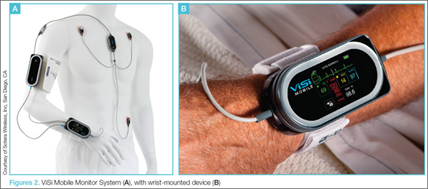
The C-MAC can also accept input from the D-Blade, which facilitates indirect intubation of anterior airways; however, it does not allow direct intubation when secretions or blood obscure the camera, though there is a suction channel that assists in clearing secretions. The clinician can also add a nasal pharyngeal scope as well as an adult or pediatric bronchoscope. The modularity of the C-MAC system is therefore a flexible addition to any airway armamentarium.
Regarding its use in emergency medicine, in addition to cost considerations, a potential concern is the ability of the plastic adapters to hold up to frequent, repetitive use in a setting such as a busy ED.
Wireless Vital Signs Monitoring Systems
Patient vital signs monitoring systems can currently double as four-point restraints. One new device, the ViSi Mobile Monitor System (Sotera Wireless, Inc, San Diego, CA), however, may make this a thing of the past.6 This system allows for inpatient monitoring of respiratory rate (RR), pulse oximetry, continuous blood pressure (BP), and temperature, as well as a multilead electrocardiogram. The entire system attaches to a small wrist-mounted device, which connects to a hospital monitoring system through a WiFi network (Figures 2a and 2b).ViSi Mobile Monitor
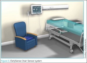
Another example of a wireless monitoring device is the EarlySense Chair Sensor system (EarlySense, Ltd, Ramat Gan, Israel) (Figure 3).7 This device assesses heart rate (HR) and RR simply by seating the patient in a chair. In the near future, this device will likely have the ability to take full vital signs. While not quite ready for prime-time in the ED, systems such as the EarlySense Chair Sensor offer a glimpse of the future in vital sign monitoring technology.
Vascular Access
Traditional intravenous (IV) line placement continues to be the standard of care for vascular access, but is not always feasible. Intraosseous needles, which have been around for decades, are seeing a new renaissance of use thanks to devices such as the Arrow EZ-IO Intraosseous Vascular Access System (Teleflex, Shavano Park, Texas).8 With these standards in mind, some new considerations are on the market, including the AV400 vein visualization system (AccuVein, Inc, Huntington, New York).
Arrow EZ-IO Intraosseous Vascular Access System
Teleflex, the maker of the EZ-IO, has recently made a push for humeral placement in order to achieve faster flow rates. Teleflex recommends using the longer needles (normally reserved for obese patients) with specific placement suggestions to facilitate retention of the needle. The Teleflex Web site8 and mobile application provide succinct, easy-to-understand instructions on placement.
AV400 Vein Visualization System
In addition to the Intraosseous Vascular Access System, the placement of an IV line may also be facilitated by laser devices such as AccuVein’s AV400 vein visualization technology. While earlier versions of both of these systems were comparable to that of a skilled technician in obtaining line placement, the latest generations of these devices have improved depth and visualization of truly difficult vascular access.
Internet-Connected Smart Glasses
In addition to the above-mentioned evolutionary changes in facilitating venous access, revolutionary technological advancements have been in development and are forthcoming. One such technology is network-connected smart glasses.
Eyes-On Glasses
Among the first in network-connected eyewear is Eyes-On Glasses (Evena Medical Inc, Los Altos, California).9 This system functions in a similar manner as other laser systems, except that the screen is a display mounted on eyeglasses, making venous placement much more intuitive (This is especially helpful for those who have difficulty translating the three-dimensional world to a two-dimensional screen).
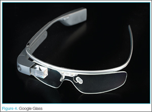
Another variation on head-mounted technology is General Electric’s (GE) beta software for Google Glass (Google Inc, Mountain View, California) (Figure 4). This prototype links a GE ultrasound machine to Google Glass via WiFi, again simultaneously facilitating visualization of the field and the screen.10 While Google Glass is not currently available for the general public, there is still a place for it in the clinical setting.
Both the Eyes-On Glasses and Google Glass devices share a common thread: to improve patient comfort and facilitate time-consuming procedures.
Wound Care
Aquacel Ag
The EP sees a fair share of burn victims, the standard of care for which has been silver sulfadiazine and daily dressing changes. Care for burn wounds is beginning to change with the introduction of antimicrobial impregnated dressings such as Aquacel Ag (ConvaTec Inc, Greensboro, North Carolina).11 Aquacel Ag comes packaged in various forms and sizes ranging from large sheets for torsos to custom formed gloves for hands. This product is safe to use on the face and can be applied to partial thickness burns where the dermal layer is gone. The fluid from the wound moistens the bandage and helps it adhere to the skin. The dressings are then left in place until they slough-off on their own (approximately 7 to 10 days after placement). Consequently, no dressing changes are required, with cosmesis matching that of classic treatment.
While EPs may find Aquacel Ag useful in treating burns that do not require inpatient hospital admission, they also will find its use highly beneficial in treating patients with “road rash,” the abrasions that occur when one wipes-out at high speeds on asphalt (eg, motorcycle accidents). As with burn wounds, only a single application of Aquacel Ag is required on a debrided abrasion.
With respect to price, a single application of Aquacel Ag costs roughly the same as multiple dressing changes with other wound-care products.12 One concern relating to the use of advanced silver-impregnated dressings is the cost of care since silver-impregnated dressings are relatively expensive compared to traditional dressings. The higher cost, however, is partially offset by the reduced use of secondary gauze, and retention dressings, as well as improved wound healing together with the reduced costs of other care. Cost-effectiveness calculations comparing Aquacel Ag to standard of care in patients with acute and chronic wounds showed favorable results using Aquacel Ag.12-18
When using these dressings, the EP should make sure the follow-up clinic is familiar with their application so that they are not inadvertently removed at the patient’s first visit.
Medication Event Monitoring Systems
There have been a couple of recent changes in medication monitoring that are beginning to make manual pill-counting a thing of the past. Earlier generations of smart pill bottles came with a timer and an alarm that chimed and lit up to alert the patient when it was time to take his or her medication. Once the bottle was opened, the system reset itself. Unfortunately, the basic nature of these systems was not able to account for the number of pills a patient ingested at each scheduled dosing.
An example of newer and more technologically advanced pill-monitoring systems is AdhereTech’s smart wireless pill bottle (AdhereTech, New York, New York). In this system, the pill bottle can be connected to a WiFi network, allowing medication information to be shared (Figure 5).19 For example, a user could have the bottle connected to his or her provider, home healthcare worker, and family member. If a patient misses a dose of medication, the appropriate person receives notification and can make contact with the patient or family member to intervene. As with earlier generation products, these systems cannot account for or prevent a patient from either overdosing or underdosing on a medication.
The patch and sensor-enabled pill system, the Ingestible Event Marker, (Proteus Digital Health, Redwood City, California), which became available this past year, provides more advanced medication monitoring.20 This system allows tracking of individual pills through small chips imbedded in the tablet (Figure 6). The chip is then monitored through a patch worn on the patient’s body. Once connected, the physician is able to not only track when a pill bottle is opened, but also when and how many tablets the patient is ingesting. Moreover, the system has the ability to perform physiologic tracking to monitor patient response to the medication.21
Each of the above systems is a huge benefit to elderly patients and their geographically-separated families. Through these devices, children and other family members can stay apprised of a parent or other loved one’s health through these at-home monitoring systems—in a similar manner as some parents track a new teenaged driver through his or her cell phone!
Other Smart Devices
Connected devices are moving past pill bottles and smart glasses. In the same manner that many people employ fitness trackers to monitor the number of steps taken and calories burned, multiple glucometers are available that sync with a patient’s smart phone, allowing upload of the data to his or her healthcare provider. This field is also growing into commercially available HR monitors that allow easy monitoring for arrhythmias in low-risk patients.
While these devices are a boon for primary care physicians and can greatly assist in determining medication noncompliance, some potential systems issues may result in a false emergency notification akin to patients presenting to the ED for evaluation after receiving an inaccurate high BP reading on a grocery-store or home monitoring device. For instance, HR monitors with a faulty lead may cause an alert from the monitoring system noting atrial fibrillation and recommending the patient seek immediate evaluation. Similarly, a smart phone-connected glucometer may note hyperglycemia in a patient after he or she has consumed a high-sugar meal.
While there has been a reemergence in the use of traditional tourniquets, they are not effective in controlling hemorrhage at junctional sites such as the groin or axilla as there is inadequate space to accommodate the tourniquet. Two recent solutions are the Combat Ready Clamp (CRoC) and SAM Junctional Tourniquet, which are specially designed to control bleeding in an improvised explosive device or blast-type injury. As with intraosseous access devices, the use of tourniquets is also making a comeback. Both owe their new-found popularity—at least in some part—to the involvement of the United States in the recent wars in Iraq and Afghanistan. High casualty rates from improvised explosive devices countered by significant improvements in body armor have resulted in preservation of the torso at the expense of extremities. Life-threatening hemorrhage from a distal extremity can easily be controlled by a tourniquet—something this author never used as an infantryman during Desert Storm, but which is now carried on the person of every soldier in the field.
The Combat Ready Clamp (Combat Medical Systems, Harrisburg, North Carolina)22 compresses the aorta and vena cava though intra-abdominal pressure (Figure 7). While some may find this device a bit cumbersome for field use, it is definitely feasible and applicable for hospital use. A similar option, the SAM Junctional Tourniquet (SAM Medical Products, Wilsonville, Oregon),23 (Figure 8) functions in a similar manner as the CROC but uses pneumatic instead of mechanical pressure. The SAM device is definitely more “rucksack friendly,” but both products are good alternatives for controlling hemorrhages in the ED.
Hemostatic agents such as QuickClot (Z-Medica, Wallingford, Connecticut)24 have been in popular use for about a decade now, and the next generation of this family of treatment options has become available. The XStat-30 (RevMedx, Wilsonville, Oregon)25 (Figure 9) is one such product. Its large syringe applicator (like a large Toomey syringe) is filled with tablets of chitin. The injector is designed to be inserted into a penetrating injury and its contents injected into the wound. Upon contact with blood, the chitin tablets expand in a similar manner as children’s “hatch-and-grow” toy eggs and capsules when immersed in water. The XStat-30 provides not only hemostasis, but also some level of tamponade.
Resuscitative Endovascular Balloon Occlusion of the Aorta
The final addition to the hemostasis comeback tour is the Resuscitative Endovascular Balloon Occlusion of the Aorta (REBOA) device (Pryor Medical, San Antonio, Texas).26 Like many of the products discussed in this article, REBOA has been around for some time, but its use had fallen out of practice. A recent reemergence has shown that REBOA benefits patients with lower abdominal, pelvic, and extremity injuries.
The principal of its use is simple: An occlusive balloon is inserted into the femoral artery and advanced to roughly the level of the midabdomen. Once inflated, the balloon stops blood flow distally. While more research needs to be done on indications and outcomes, REBOA has been successfully used in England in many hospitals and even in the field.27
Summary
Some of the most notable recent evolutionary and revolutionary technological advancements to have a significant and beneficial impact on patient care have been seen in new noninvasive tonographic devices to measure IOP; video laryngoscopic devices for airway management; wireless patient vital signs monitoring systems; alternatives to traditional vascular access such as intraosseous vascular systems, laser-assisted vein visualization technology, and Internet-connected smart glasses; advances in wound-care dressings; medication monitoring systems; clamps and tourniquets to control junctional hemorrhage; and wireless, smart-phone connected glucometer devices and HR monitors. Many of these devices and systems are applicable and appropriate for use in the ED, the implementation of which will further facilitate and improve the quality of patient care.
Dr Wagner is an assistant professor of emergency medicine; program director for the emergency medicine residency program; and director of augmented learning at Barnes-Jewish Hospital, Saint Louis, Missouri.
The author invites readers to contact him via Twitter @TheTechDoc with suggestions for future devices.
The views expressed in this article are those of the author and do not represent the views or opinions of the editorial staff, the editorial board or the publisher.
- iCare Tonometer. iCare Finland. http://www.icaretonometer.com/products/icare-ta01/. Accessed June 2, 2015.
- García-Resúa C, González-Meijome JM, Gilino J, Yebra-Pimentel E. Accuracy of the new ICare rebound tonometer vs. other portable tonometers in healthy eyes. Optom Vis Sci. 2006;83(2):102-107.
- Reichert Technologies. Tono-Pen & Ocu-Film +. http://www.reichert.com/products.cfm?pcId=474. Accessed June 2, 2015.
- Karl Storz-Endoskope. From Laryngoscopy to Video Laryngoscopy. The history of endotracheal intubation. https://www.karlstorz.com/cps/rde/xbcr/karlstorz_assets/ASSETS/2133990.pdf. Accessed May 5, 2015.
- Lipe DN, Lindstrom R, Tauferner D, Mitchell C, Moffett P. Evaluation of Karl Storz C-MAC Tip Device Versus Traditional Airway Suction in a Cadaver Model. West J Emerg Med. 2014;15(4):548-553.
- ViSi Mobile. Sotera Wireless. http://www.visimobile.com/. Accessed May 6, 2015.
- EarlySense Chair Sensor Receives FDA Clearance [press release]. Waltham, MA:Early Sense; July 2, 2014. http://www.earlysense.com/news-and-events/news/jul-2-2014/. Accessed May 6, 2015.
- Arrow EZ-10. Teleflex. http://www.arrowezio.com/. Accessed May 6, 2015.
- Evena Medical Eyes-On Glass 1.0. http://evenamed.com/~even5672/~even5672/products/glasses. Accessed May 6, 2015.
- Wu TS, Dameff CJ, Tully JL. Ultrasound-guided central venous access using google glass. J Emerg Med. 2014;47(6):668-675.
- Aquacel Ag Dressing. ConvaTec. http://www.convatec.com/wound-skin/aquacel-ag-dressing. Accessed May 6, 2015.
- A review of the applications of the hydrofiber dressing with silver (Aquacel Ag) in wound care. Ther Clin Risk Manag. 2010;6:21-27.
- Caruso DM, Foster KN, Blome-Eberwein SA, et al. Randomized clinical study of Hydrofiber dressing with silver or silver sulfadiazine in the management of partial-thickness burns. J Burn Care Res. 2006;27(3):298–309.
- Kaźmierski M, Mańkowski P, Jankowski A, Harasymczuk J. Comparison of the results of operative and conservative treatment of deep dermal partial-thickness scalds in children. Eur J Pediatr Surg. 2007;17(5):354–361.
- Lohana P, Potokar TS. Aquacel Ag in paediatric burns: a prospective audit. Ann Burns Fire Disasters. 2006;19(3):144-147.
- Paddock HN, Fabia R, Giles S, et al. A silver-impregnated antimicrobial dressing reduces hospital costs for pediatric burn patients. J Pediatr Surg. 2007;42(1):211–213.
- Saba SC, Tsai R, Glat P. Clinical evaluation comparing the efficacy of aquacel ag hydrofiber dressing versus petrolatum gauze with antibiotic ointment in partial-thickness burns in a pediatric burn center. J Burn Care Res. 2009;30(3):380–385.
- Scanlon E, Karlsmark T, Leaper DJ, et al. Cost-effective faster wound healing with a sustained silver-releasing foam dressing in delayed healing leg ulcers-a health-economic analysis. Int Wound J. 2005;2(2):150-160.
- Smart Wireless Pill Bottles. AdhereTech. http://adheretech.com/. Accessed May 6, 2015.
- Proteus Digital Health. http://www.proteus.com/. Accessed May 6, 2015.
- Kim E. ‘Digital pill’ with chip inside gets FDA green light. CNN Money. http://money.cnn.com/2012/08/03/technology/startups/ingestible-sensor-proteus/. Accessed May 6, 2015.
- CROC Combat Ready Clamp (CRoC). Combat Medical. http://combatmedicalsystems.com/products/prod_massivehem_croc/ Accessed May 6, 2015.
- SAM Junctional Tourniquet. SAM Medical Products. http://www.sammedical.com/products/the-sam-junctional-tourniquet/. Accessed May 6, 2015.
- QuikClot hemostatic devices help patients survive traumatic blood loss. QuikClot. http://www.quikclot.com/. Accessed May 6, 2015.
- Revmedx. Revolutionary Medical Technologies. http://www.revmedx.com/#!xstat-dressing/c2500. Accessed May 6, 2015.
- Stannard A, Eliason JL, Rasmussen TE. Resuscitative Endovascular Balloon Occlusion of the Aorta (REBOA) as an adjunct for hemorrhagic shock J Trauma. 2011;71(6):1869-1872.
- London’s Air Ambulance Performs World’s First Prehospital REBOA. EMSWORLD – Patient Care. http://www.emsworld.com/news/11545597/londons-air-ambulance-performs-worlds-first-prehospital-reboa. Published July 2, 2014. Accessed May 6, 2015.
Emergency physicians (EPs) are always interested in what are the “tried-and-true” as well as the “latest-and-greatest” devices that will provide the best results for their patients. This article, while not a comprehensive list of every such device introduced over the past few years, does provide an overview of the most notable ones applicable for use in the ED.
Tonometry
The standard iCare tonometer device (TA01i; iCare Finland Oy, Vantaa, Finland),1 began to gain acceptance in the United States in 2007 (Figure 1). Early studies2 have shown its measurement accuracy of intraocular pressure (IOP) to be equivalent to traditional tonometers such as the Tono-Pen XL Applanation Tonometer (Reichert Techonologies, Depew, New York).3
The iCare tonometer is easy to calibrate and use. Consisting of a pin inserted into a magnetic housing, the magnet quickly pushes the blunt end of the pin out to make contact with the cornea. Six quick measurements provide the clinician with an average IOP. The device can be used without anesthesia and is also applicable for at-home use.
Airway Devices
C-MAC Tip System
While direct laryngoscopy will always have a role in clinical practice, there has been a revolution in airway management over the past few years, with video laryngoscopy rapidly replacing direct laryngoscopy. The C-MAC Tip system (Karl Storz Endoscopy-America, Inc, El Segundo, California) is one of the devices currently available.4,5 While this device is not at the lower end of the cost spectrum in airway devices, it is, in this author’s opinion, among the highest quality video laryngoscopes on the market. The hub of C-MAC Tip system is a video screen that accepts input from multiple devices. The most common is the video MacIntosh blade, which is shaped like a traditional MacIntosh but with a slightly thicker handle—allowing both direct and indirect intubation.
The C-MAC Tip system is a great teaching tool, allowing learners to perform direct laryngoscopy while providing reassuring visualization to the instructor of the intubation on the screen. (No longer does the instructor need to repeatedly ask the learner what he or she is viewing!) Moreover, when required, the clinician performing the intubation can look at the screen to benefit from the superior visualization of indirect laryngoscopy.
The C-MAC can also accept input from the D-Blade, which facilitates indirect intubation of anterior airways; however, it does not allow direct intubation when secretions or blood obscure the camera, though there is a suction channel that assists in clearing secretions. The clinician can also add a nasal pharyngeal scope as well as an adult or pediatric bronchoscope. The modularity of the C-MAC system is therefore a flexible addition to any airway armamentarium.
Regarding its use in emergency medicine, in addition to cost considerations, a potential concern is the ability of the plastic adapters to hold up to frequent, repetitive use in a setting such as a busy ED.
Wireless Vital Signs Monitoring Systems
Patient vital signs monitoring systems can currently double as four-point restraints. One new device, the ViSi Mobile Monitor System (Sotera Wireless, Inc, San Diego, CA), however, may make this a thing of the past.6 This system allows for inpatient monitoring of respiratory rate (RR), pulse oximetry, continuous blood pressure (BP), and temperature, as well as a multilead electrocardiogram. The entire system attaches to a small wrist-mounted device, which connects to a hospital monitoring system through a WiFi network (Figures 2a and 2b).ViSi Mobile Monitor
Another example of a wireless monitoring device is the EarlySense Chair Sensor system (EarlySense, Ltd, Ramat Gan, Israel) (Figure 3).7 This device assesses heart rate (HR) and RR simply by seating the patient in a chair. In the near future, this device will likely have the ability to take full vital signs. While not quite ready for prime-time in the ED, systems such as the EarlySense Chair Sensor offer a glimpse of the future in vital sign monitoring technology.
Vascular Access
Traditional intravenous (IV) line placement continues to be the standard of care for vascular access, but is not always feasible. Intraosseous needles, which have been around for decades, are seeing a new renaissance of use thanks to devices such as the Arrow EZ-IO Intraosseous Vascular Access System (Teleflex, Shavano Park, Texas).8 With these standards in mind, some new considerations are on the market, including the AV400 vein visualization system (AccuVein, Inc, Huntington, New York).
Arrow EZ-IO Intraosseous Vascular Access System
Teleflex, the maker of the EZ-IO, has recently made a push for humeral placement in order to achieve faster flow rates. Teleflex recommends using the longer needles (normally reserved for obese patients) with specific placement suggestions to facilitate retention of the needle. The Teleflex Web site8 and mobile application provide succinct, easy-to-understand instructions on placement.
AV400 Vein Visualization System
In addition to the Intraosseous Vascular Access System, the placement of an IV line may also be facilitated by laser devices such as AccuVein’s AV400 vein visualization technology. While earlier versions of both of these systems were comparable to that of a skilled technician in obtaining line placement, the latest generations of these devices have improved depth and visualization of truly difficult vascular access.
Internet-Connected Smart Glasses
In addition to the above-mentioned evolutionary changes in facilitating venous access, revolutionary technological advancements have been in development and are forthcoming. One such technology is network-connected smart glasses.
Eyes-On Glasses
Among the first in network-connected eyewear is Eyes-On Glasses (Evena Medical Inc, Los Altos, California).9 This system functions in a similar manner as other laser systems, except that the screen is a display mounted on eyeglasses, making venous placement much more intuitive (This is especially helpful for those who have difficulty translating the three-dimensional world to a two-dimensional screen).
Another variation on head-mounted technology is General Electric’s (GE) beta software for Google Glass (Google Inc, Mountain View, California) (Figure 4). This prototype links a GE ultrasound machine to Google Glass via WiFi, again simultaneously facilitating visualization of the field and the screen.10 While Google Glass is not currently available for the general public, there is still a place for it in the clinical setting.
Both the Eyes-On Glasses and Google Glass devices share a common thread: to improve patient comfort and facilitate time-consuming procedures.
Wound Care
Aquacel Ag
The EP sees a fair share of burn victims, the standard of care for which has been silver sulfadiazine and daily dressing changes. Care for burn wounds is beginning to change with the introduction of antimicrobial impregnated dressings such as Aquacel Ag (ConvaTec Inc, Greensboro, North Carolina).11 Aquacel Ag comes packaged in various forms and sizes ranging from large sheets for torsos to custom formed gloves for hands. This product is safe to use on the face and can be applied to partial thickness burns where the dermal layer is gone. The fluid from the wound moistens the bandage and helps it adhere to the skin. The dressings are then left in place until they slough-off on their own (approximately 7 to 10 days after placement). Consequently, no dressing changes are required, with cosmesis matching that of classic treatment.
While EPs may find Aquacel Ag useful in treating burns that do not require inpatient hospital admission, they also will find its use highly beneficial in treating patients with “road rash,” the abrasions that occur when one wipes-out at high speeds on asphalt (eg, motorcycle accidents). As with burn wounds, only a single application of Aquacel Ag is required on a debrided abrasion.
With respect to price, a single application of Aquacel Ag costs roughly the same as multiple dressing changes with other wound-care products.12 One concern relating to the use of advanced silver-impregnated dressings is the cost of care since silver-impregnated dressings are relatively expensive compared to traditional dressings. The higher cost, however, is partially offset by the reduced use of secondary gauze, and retention dressings, as well as improved wound healing together with the reduced costs of other care. Cost-effectiveness calculations comparing Aquacel Ag to standard of care in patients with acute and chronic wounds showed favorable results using Aquacel Ag.12-18
When using these dressings, the EP should make sure the follow-up clinic is familiar with their application so that they are not inadvertently removed at the patient’s first visit.
Medication Event Monitoring Systems
There have been a couple of recent changes in medication monitoring that are beginning to make manual pill-counting a thing of the past. Earlier generations of smart pill bottles came with a timer and an alarm that chimed and lit up to alert the patient when it was time to take his or her medication. Once the bottle was opened, the system reset itself. Unfortunately, the basic nature of these systems was not able to account for the number of pills a patient ingested at each scheduled dosing.
An example of newer and more technologically advanced pill-monitoring systems is AdhereTech’s smart wireless pill bottle (AdhereTech, New York, New York). In this system, the pill bottle can be connected to a WiFi network, allowing medication information to be shared (Figure 5).19 For example, a user could have the bottle connected to his or her provider, home healthcare worker, and family member. If a patient misses a dose of medication, the appropriate person receives notification and can make contact with the patient or family member to intervene. As with earlier generation products, these systems cannot account for or prevent a patient from either overdosing or underdosing on a medication.
The patch and sensor-enabled pill system, the Ingestible Event Marker, (Proteus Digital Health, Redwood City, California), which became available this past year, provides more advanced medication monitoring.20 This system allows tracking of individual pills through small chips imbedded in the tablet (Figure 6). The chip is then monitored through a patch worn on the patient’s body. Once connected, the physician is able to not only track when a pill bottle is opened, but also when and how many tablets the patient is ingesting. Moreover, the system has the ability to perform physiologic tracking to monitor patient response to the medication.21
Each of the above systems is a huge benefit to elderly patients and their geographically-separated families. Through these devices, children and other family members can stay apprised of a parent or other loved one’s health through these at-home monitoring systems—in a similar manner as some parents track a new teenaged driver through his or her cell phone!
Other Smart Devices
Connected devices are moving past pill bottles and smart glasses. In the same manner that many people employ fitness trackers to monitor the number of steps taken and calories burned, multiple glucometers are available that sync with a patient’s smart phone, allowing upload of the data to his or her healthcare provider. This field is also growing into commercially available HR monitors that allow easy monitoring for arrhythmias in low-risk patients.
While these devices are a boon for primary care physicians and can greatly assist in determining medication noncompliance, some potential systems issues may result in a false emergency notification akin to patients presenting to the ED for evaluation after receiving an inaccurate high BP reading on a grocery-store or home monitoring device. For instance, HR monitors with a faulty lead may cause an alert from the monitoring system noting atrial fibrillation and recommending the patient seek immediate evaluation. Similarly, a smart phone-connected glucometer may note hyperglycemia in a patient after he or she has consumed a high-sugar meal.
While there has been a reemergence in the use of traditional tourniquets, they are not effective in controlling hemorrhage at junctional sites such as the groin or axilla as there is inadequate space to accommodate the tourniquet. Two recent solutions are the Combat Ready Clamp (CRoC) and SAM Junctional Tourniquet, which are specially designed to control bleeding in an improvised explosive device or blast-type injury. As with intraosseous access devices, the use of tourniquets is also making a comeback. Both owe their new-found popularity—at least in some part—to the involvement of the United States in the recent wars in Iraq and Afghanistan. High casualty rates from improvised explosive devices countered by significant improvements in body armor have resulted in preservation of the torso at the expense of extremities. Life-threatening hemorrhage from a distal extremity can easily be controlled by a tourniquet—something this author never used as an infantryman during Desert Storm, but which is now carried on the person of every soldier in the field.
The Combat Ready Clamp (Combat Medical Systems, Harrisburg, North Carolina)22 compresses the aorta and vena cava though intra-abdominal pressure (Figure 7). While some may find this device a bit cumbersome for field use, it is definitely feasible and applicable for hospital use. A similar option, the SAM Junctional Tourniquet (SAM Medical Products, Wilsonville, Oregon),23 (Figure 8) functions in a similar manner as the CROC but uses pneumatic instead of mechanical pressure. The SAM device is definitely more “rucksack friendly,” but both products are good alternatives for controlling hemorrhages in the ED.
Hemostatic agents such as QuickClot (Z-Medica, Wallingford, Connecticut)24 have been in popular use for about a decade now, and the next generation of this family of treatment options has become available. The XStat-30 (RevMedx, Wilsonville, Oregon)25 (Figure 9) is one such product. Its large syringe applicator (like a large Toomey syringe) is filled with tablets of chitin. The injector is designed to be inserted into a penetrating injury and its contents injected into the wound. Upon contact with blood, the chitin tablets expand in a similar manner as children’s “hatch-and-grow” toy eggs and capsules when immersed in water. The XStat-30 provides not only hemostasis, but also some level of tamponade.
Resuscitative Endovascular Balloon Occlusion of the Aorta
The final addition to the hemostasis comeback tour is the Resuscitative Endovascular Balloon Occlusion of the Aorta (REBOA) device (Pryor Medical, San Antonio, Texas).26 Like many of the products discussed in this article, REBOA has been around for some time, but its use had fallen out of practice. A recent reemergence has shown that REBOA benefits patients with lower abdominal, pelvic, and extremity injuries.
The principal of its use is simple: An occlusive balloon is inserted into the femoral artery and advanced to roughly the level of the midabdomen. Once inflated, the balloon stops blood flow distally. While more research needs to be done on indications and outcomes, REBOA has been successfully used in England in many hospitals and even in the field.27
Summary
Some of the most notable recent evolutionary and revolutionary technological advancements to have a significant and beneficial impact on patient care have been seen in new noninvasive tonographic devices to measure IOP; video laryngoscopic devices for airway management; wireless patient vital signs monitoring systems; alternatives to traditional vascular access such as intraosseous vascular systems, laser-assisted vein visualization technology, and Internet-connected smart glasses; advances in wound-care dressings; medication monitoring systems; clamps and tourniquets to control junctional hemorrhage; and wireless, smart-phone connected glucometer devices and HR monitors. Many of these devices and systems are applicable and appropriate for use in the ED, the implementation of which will further facilitate and improve the quality of patient care.
Dr Wagner is an assistant professor of emergency medicine; program director for the emergency medicine residency program; and director of augmented learning at Barnes-Jewish Hospital, Saint Louis, Missouri.
The author invites readers to contact him via Twitter @TheTechDoc with suggestions for future devices.
The views expressed in this article are those of the author and do not represent the views or opinions of the editorial staff, the editorial board or the publisher.
- iCare Tonometer. iCare Finland. http://www.icaretonometer.com/products/icare-ta01/. Accessed June 2, 2015.
- García-Resúa C, González-Meijome JM, Gilino J, Yebra-Pimentel E. Accuracy of the new ICare rebound tonometer vs. other portable tonometers in healthy eyes. Optom Vis Sci. 2006;83(2):102-107.
- Reichert Technologies. Tono-Pen & Ocu-Film +. http://www.reichert.com/products.cfm?pcId=474. Accessed June 2, 2015.
- Karl Storz-Endoskope. From Laryngoscopy to Video Laryngoscopy. The history of endotracheal intubation. https://www.karlstorz.com/cps/rde/xbcr/karlstorz_assets/ASSETS/2133990.pdf. Accessed May 5, 2015.
- Lipe DN, Lindstrom R, Tauferner D, Mitchell C, Moffett P. Evaluation of Karl Storz C-MAC Tip Device Versus Traditional Airway Suction in a Cadaver Model. West J Emerg Med. 2014;15(4):548-553.
- ViSi Mobile. Sotera Wireless. http://www.visimobile.com/. Accessed May 6, 2015.
- EarlySense Chair Sensor Receives FDA Clearance [press release]. Waltham, MA:Early Sense; July 2, 2014. http://www.earlysense.com/news-and-events/news/jul-2-2014/. Accessed May 6, 2015.
- Arrow EZ-10. Teleflex. http://www.arrowezio.com/. Accessed May 6, 2015.
- Evena Medical Eyes-On Glass 1.0. http://evenamed.com/~even5672/~even5672/products/glasses. Accessed May 6, 2015.
- Wu TS, Dameff CJ, Tully JL. Ultrasound-guided central venous access using google glass. J Emerg Med. 2014;47(6):668-675.
- Aquacel Ag Dressing. ConvaTec. http://www.convatec.com/wound-skin/aquacel-ag-dressing. Accessed May 6, 2015.
- A review of the applications of the hydrofiber dressing with silver (Aquacel Ag) in wound care. Ther Clin Risk Manag. 2010;6:21-27.
- Caruso DM, Foster KN, Blome-Eberwein SA, et al. Randomized clinical study of Hydrofiber dressing with silver or silver sulfadiazine in the management of partial-thickness burns. J Burn Care Res. 2006;27(3):298–309.
- Kaźmierski M, Mańkowski P, Jankowski A, Harasymczuk J. Comparison of the results of operative and conservative treatment of deep dermal partial-thickness scalds in children. Eur J Pediatr Surg. 2007;17(5):354–361.
- Lohana P, Potokar TS. Aquacel Ag in paediatric burns: a prospective audit. Ann Burns Fire Disasters. 2006;19(3):144-147.
- Paddock HN, Fabia R, Giles S, et al. A silver-impregnated antimicrobial dressing reduces hospital costs for pediatric burn patients. J Pediatr Surg. 2007;42(1):211–213.
- Saba SC, Tsai R, Glat P. Clinical evaluation comparing the efficacy of aquacel ag hydrofiber dressing versus petrolatum gauze with antibiotic ointment in partial-thickness burns in a pediatric burn center. J Burn Care Res. 2009;30(3):380–385.
- Scanlon E, Karlsmark T, Leaper DJ, et al. Cost-effective faster wound healing with a sustained silver-releasing foam dressing in delayed healing leg ulcers-a health-economic analysis. Int Wound J. 2005;2(2):150-160.
- Smart Wireless Pill Bottles. AdhereTech. http://adheretech.com/. Accessed May 6, 2015.
- Proteus Digital Health. http://www.proteus.com/. Accessed May 6, 2015.
- Kim E. ‘Digital pill’ with chip inside gets FDA green light. CNN Money. http://money.cnn.com/2012/08/03/technology/startups/ingestible-sensor-proteus/. Accessed May 6, 2015.
- CROC Combat Ready Clamp (CRoC). Combat Medical. http://combatmedicalsystems.com/products/prod_massivehem_croc/ Accessed May 6, 2015.
- SAM Junctional Tourniquet. SAM Medical Products. http://www.sammedical.com/products/the-sam-junctional-tourniquet/. Accessed May 6, 2015.
- QuikClot hemostatic devices help patients survive traumatic blood loss. QuikClot. http://www.quikclot.com/. Accessed May 6, 2015.
- Revmedx. Revolutionary Medical Technologies. http://www.revmedx.com/#!xstat-dressing/c2500. Accessed May 6, 2015.
- Stannard A, Eliason JL, Rasmussen TE. Resuscitative Endovascular Balloon Occlusion of the Aorta (REBOA) as an adjunct for hemorrhagic shock J Trauma. 2011;71(6):1869-1872.
- London’s Air Ambulance Performs World’s First Prehospital REBOA. EMSWORLD – Patient Care. http://www.emsworld.com/news/11545597/londons-air-ambulance-performs-worlds-first-prehospital-reboa. Published July 2, 2014. Accessed May 6, 2015.
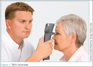
Emergency Ultrasound: Pneumothorax Assessment
Background
In practiced hands, ultrasound is more sensitive than chest X-ray in evaluating patients with suspected pneumothorax. Due to its portability, this modality can rapidly identify pathology and facilitate prompt intervention in a decompensating patient. This article reviews the proper techniques for evaluating patients for pneumothorax as well as the classic signs indicative of this condition.
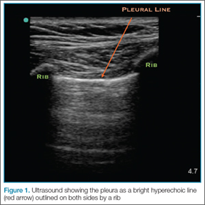
Performing the Scan
The probe also should be oriented as perpendicular to the chest wall as possible, which will make the pleura appear brighter. Once this view is achieved, the clinician can evaluate for evidence of lung sliding. Since air in pneumothorax rises to the least dependent portion of the chest, this is the area that should be evaluated. In the supine patient, the probe is placed on the anterior chest wall in the second intercostal space, midclavicular line. A high-frequency linear probe is best for evaluating pneumothorax and should be positioned with the indicator marker toward the head. The clinician will need to adjust the probe to visualize the pleura, which will appear as a bright hyperechoic line outlined on both sides by a rib with shadowing beneath (Figure 1).
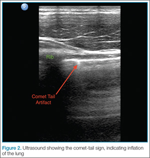
Lung Siding and Comet-Tail Artifacts
The appearance of lung sliding or a comet-tail artifact on the ultrasound confirms the lung is inflated. Lung sliding has been described as a shimmering appearance of the pleura, or like tiny ants marching on a string. The pleura will seem to slide back and forth as the patient breathes. Comet tails, vertical artifacts originating from the pleura, may be visible on ultrasound, also proving the lung is inflated (Figure 2).
The Lung Point
By continuing to scan laterally down the chest, the clinician may encounter the “lung point”—the junction between the normally inflated lung and pneumothorax. This point moves with respiration, and if visualized, confirms pneumothorax.
Motion Mode
Since lung sliding is sometimes challenging to visualize, using the motion mode (M-mode) on ultrasound can help to confirm findings. The M-mode takes a single line of echoes from the two-dimensional image and plots it against time. (The manner in which the image is produced may be thought of as a graph, with the x-axis representing time and the y-axis the depth.) When using M-mode, the screen will vary in appearance depending on the type of ultrasound being used. While performing the ultrasound, it is important to always keep the probe as still as possible to identify independent motion at the pleura.
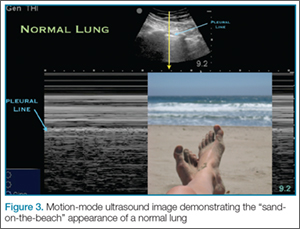
Sand-on-the-Beach Sign
In a normal lung, M-mode images are often described as having a “sand-on-the-beach” appearance (Figure 3). As a normal lung inflates, the motion of the lung changes the brightness of the echoes that return to the machine, creating a speckled appearance like grains of sand beneath the bright pleural line. The soft tissues above the pleural line do not vary with time and thus have a linear appearance.
Barcode or Stratosphere Sign
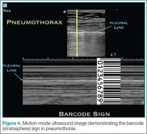
In pneumothorax, however, the granular sand appearance is absent. Instead, the M-mode shows a linear pattern below the pleural line. This pattern is described as the “barcode sign” or “stratosphere sign” (Figure 4).
Pitfalls
There are several pitfalls that can limit the ability to correctly diagnose a pneumothorax. The presence of scarring and adhesions may cause the patient to develop loculated air collections. If one evaluates only the anterior chest, air trapped in another location may be missed. The clinician should also be mindful of the presence of bullae as the appearance of sliding may be diminished in patients with bullous disease. Using the M-mode in these cases may help to identify inflated lung in patients with limited movement at the pleural line.
Furthermore, since it is easy to confuse a bright layer of fascia with the pleura, the clinician should always make sure to identify landmarks. In some cases of pneumothorax, subcutaneous air may obscure the pleura. The ribs should always be identified to ensure one is looking at the pleural line.
Although absence of lung sliding can suggest pneumothorax, other conditions, such as severe consolidation, acute respiratory distress syndrome, and mainstem intubation, can give a similar appearance. Remember, visualization of the lung point is pathnognomic for pneumothorax.
Conclusion
Pneumothorax is a medical emergency requiring immediate diagnosis and treatment. Patients presenting with suspected pneumothorax can be assessed quickly through bedside ultrasound. Once visualization of the pleura is established, the lung may be assessed for the presence or absence of normal lung sliding and comet-tail artifacts. The M-mode setting further enhances visualization and aids in the diagnosis of pneumothorax.
Dr Beck is an assistant professor, department of emergency medicine, Emory University School of Medicine, Atlanta, Georgia. Dr Meer is an assistant professor and director of emergency ultrasound, department of emergency medicine, Emory University School of Medicine, Atlanta, Georgia. Dr Taylor is an assistant professor and director of postgraduate medical education, department of emergency medicine, Emory University School of Medicine, Atlanta, Georgia.
An example of ultrasound demonstrating normal lung sliding, no sliding, and lung point in the presence of pneumothorax may be accessed at https://youtu.be/gRmPh_j_RE8.
Additional information and a video demonstrating lung sliding, may be accessed at http://www.em.emory.edu/ultrasound/ImageWeek/2012/lung_point.html.
Background
In practiced hands, ultrasound is more sensitive than chest X-ray in evaluating patients with suspected pneumothorax. Due to its portability, this modality can rapidly identify pathology and facilitate prompt intervention in a decompensating patient. This article reviews the proper techniques for evaluating patients for pneumothorax as well as the classic signs indicative of this condition.
Performing the Scan
The probe also should be oriented as perpendicular to the chest wall as possible, which will make the pleura appear brighter. Once this view is achieved, the clinician can evaluate for evidence of lung sliding. Since air in pneumothorax rises to the least dependent portion of the chest, this is the area that should be evaluated. In the supine patient, the probe is placed on the anterior chest wall in the second intercostal space, midclavicular line. A high-frequency linear probe is best for evaluating pneumothorax and should be positioned with the indicator marker toward the head. The clinician will need to adjust the probe to visualize the pleura, which will appear as a bright hyperechoic line outlined on both sides by a rib with shadowing beneath (Figure 1).
Lung Siding and Comet-Tail Artifacts
The appearance of lung sliding or a comet-tail artifact on the ultrasound confirms the lung is inflated. Lung sliding has been described as a shimmering appearance of the pleura, or like tiny ants marching on a string. The pleura will seem to slide back and forth as the patient breathes. Comet tails, vertical artifacts originating from the pleura, may be visible on ultrasound, also proving the lung is inflated (Figure 2).
The Lung Point
By continuing to scan laterally down the chest, the clinician may encounter the “lung point”—the junction between the normally inflated lung and pneumothorax. This point moves with respiration, and if visualized, confirms pneumothorax.
Motion Mode
Since lung sliding is sometimes challenging to visualize, using the motion mode (M-mode) on ultrasound can help to confirm findings. The M-mode takes a single line of echoes from the two-dimensional image and plots it against time. (The manner in which the image is produced may be thought of as a graph, with the x-axis representing time and the y-axis the depth.) When using M-mode, the screen will vary in appearance depending on the type of ultrasound being used. While performing the ultrasound, it is important to always keep the probe as still as possible to identify independent motion at the pleura.
Sand-on-the-Beach Sign
In a normal lung, M-mode images are often described as having a “sand-on-the-beach” appearance (Figure 3). As a normal lung inflates, the motion of the lung changes the brightness of the echoes that return to the machine, creating a speckled appearance like grains of sand beneath the bright pleural line. The soft tissues above the pleural line do not vary with time and thus have a linear appearance.
Barcode or Stratosphere Sign
In pneumothorax, however, the granular sand appearance is absent. Instead, the M-mode shows a linear pattern below the pleural line. This pattern is described as the “barcode sign” or “stratosphere sign” (Figure 4).
Pitfalls
There are several pitfalls that can limit the ability to correctly diagnose a pneumothorax. The presence of scarring and adhesions may cause the patient to develop loculated air collections. If one evaluates only the anterior chest, air trapped in another location may be missed. The clinician should also be mindful of the presence of bullae as the appearance of sliding may be diminished in patients with bullous disease. Using the M-mode in these cases may help to identify inflated lung in patients with limited movement at the pleural line.
Furthermore, since it is easy to confuse a bright layer of fascia with the pleura, the clinician should always make sure to identify landmarks. In some cases of pneumothorax, subcutaneous air may obscure the pleura. The ribs should always be identified to ensure one is looking at the pleural line.
Although absence of lung sliding can suggest pneumothorax, other conditions, such as severe consolidation, acute respiratory distress syndrome, and mainstem intubation, can give a similar appearance. Remember, visualization of the lung point is pathnognomic for pneumothorax.
Conclusion
Pneumothorax is a medical emergency requiring immediate diagnosis and treatment. Patients presenting with suspected pneumothorax can be assessed quickly through bedside ultrasound. Once visualization of the pleura is established, the lung may be assessed for the presence or absence of normal lung sliding and comet-tail artifacts. The M-mode setting further enhances visualization and aids in the diagnosis of pneumothorax.
Dr Beck is an assistant professor, department of emergency medicine, Emory University School of Medicine, Atlanta, Georgia. Dr Meer is an assistant professor and director of emergency ultrasound, department of emergency medicine, Emory University School of Medicine, Atlanta, Georgia. Dr Taylor is an assistant professor and director of postgraduate medical education, department of emergency medicine, Emory University School of Medicine, Atlanta, Georgia.
An example of ultrasound demonstrating normal lung sliding, no sliding, and lung point in the presence of pneumothorax may be accessed at https://youtu.be/gRmPh_j_RE8.
Additional information and a video demonstrating lung sliding, may be accessed at http://www.em.emory.edu/ultrasound/ImageWeek/2012/lung_point.html.
