User login
VIDEO: Functional noninvasive imaging cuts unnecessary angiography
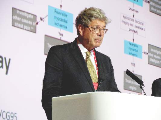
ROME – Functional, noninvasive cardiac imaging using cardiovascular MR or myocardial perfusion scintigraphy was significantly better than was a current and well regarded guideline-based approach to identifying patients with chest pain and suspected coronary artery disease who could safely avoid angiography, thereby cutting the rate of unnecessary angiography by about 75%.
Following the guideline formula adopted by the British National Institute for Health and Care Excellence (NICE) resulted in a 29% rate of unnecessary angiography compared with rates of 7.5% using cardiovascular MR (CMR) and 7.1% using myocardial perfusion scintigraphy (MPS) in a multicenter randomized trial with 1,202 patients, John P. Greenwood, MBChB, said at the annual congress of the European Society of Cardiology.

This universal use of a functional, noninvasive imaging strategy to guide angiography resulted in no significant penalty of missed coronary disease or subsequent coronary events. The rate of positive angiography findings was 12% among the 240 patients managed according to the NICE guidelines, 10% among 481 patients screened by CMR, and 9% among the 481 patients screened using MPS, reported Dr. Greenwood, professor of cardiology at the University of Leeds (England). The rate of major adverse coronary events after 12 months of follow-up were 3% following the NICE protocol and 4% when screening by CMR or with MPS.
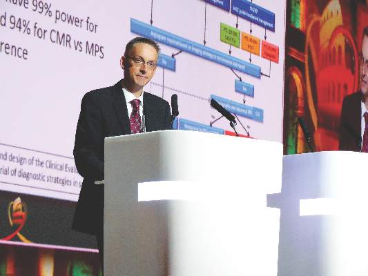
Concurrently with Dr. Greenwood’s report, the findings from the Clinical Evaluation of Magnetic Resonance Imaging in Coronary Heart Disease 2 (CE-MARC2) study appeared in an article online (JAMA. 2016 Aug 29. doi: 10.1001/jama.2016.12680).
“We showed that a functional test with CMR or MPS can reduce the rate of unnecessary coronary angiography. Cutting unnecessary angiography is really important to patients, and it may also cost effective,” he said, but cautioned that a formal cost analysis of the options tested in this study is still being run.
The NICE guidelines manage patients with chest pain that could be angina by their pretest probability of having coronary artery disease (CAD), and at the time the study was designed the NICE guidelines, issued in 2010, provided the most up-to-date expert guidance on how to triage these patients. The study enrolled patients with a pretest probability for CAD of 10%-90%; collectively their average probability was 50%. The patients participated in the study at one of six U.K. centers during November 2012 to March 2015. The average age was 56 years.
MPS is “probably the noninvasive imaging approach most commonly used worldwide to detect coronary ischemia,” Dr. Greenwood said. But he led an earlier study that showed that CMR, using a gadolinium-based tracing agent, works even better than MPS (in this study single photon emission CT) to predict a patient’s risk for major cardiac events. He said this superiority is probably because of the greater spatial resolution with CMR.
“The higher spatial resolution of CMR, about 5- to 10-fold greater that MPS, is less likely to produce false negative results,” he said in an interview. “We showed that CMR has higher diagnostic accuracy, is a better prognosticator, and is more cost effective” than MPS. Dr. Greenwood attributed the similar performance of CMR and MPS in CE-MARC2 to the study’s design, which led to fewer patients undergoing each of the two imaging methods and made CE-MARC2 underpowered to discern a difference in specificity. In his earlier study, which included 752 patients who underwent examination with both CMR and MPS, the negative predictive value of CMR was 91% compared with 79% with MPS.
CMR uses conventional MR machines, is now widely available, and is being widely used today as a first-line test in the United Kingdom and Europe, he added.
Dr. Greenwood believes that in his new study functional imaging outperformed the NICE guidelines because the pretest models used in the guidelines “tend to overestimate risk,” the factor that produces angiography overuse.
His report included two additional analyses that assessed the impact of CMR and MPS in the subgroup of patients with a high pretest probability for CAD, 61%-90%, and in the subgroup with a low pretest probability, 10%-29%. Among the patients with a high likelihood for CAD the two functional imaging methods cut the rate of unnecessary angiography by 95%, a statistically significant difference. Among those with a low likelihood functional imaging cut the rate 56%, a difference that did not reach statistical significance.
[email protected]
On Twitter @mitchelzoler
The video associated with this article is no longer available on this site. Please view all of our videos on the MDedge YouTube channel
The results from CE-MARC2 very nicely showed that imaging-guided angiography is as safe as compulsory angiography in the highest-risk subgroup of the enrolled patients, those with a pretest probability of 61%-90% for having coronary artery disease. Findings from the economic analysis of this study that remains pending will be crucial for eventually recommending one strategy over the other in this setting.
|
| Mitchel L. Zoler/Frontline Medical News Dr. Udo Sechtem |
The 12-month rate of the hardest clinical endpoints measured in this study, cardiovascular deaths and MIs, was very low in this study: 1.3% in the patients managed with NICE guidance, 1% in those who first underwent cardiovascular MR, and 0.8% in the patients who first underwent myocardial perfusion scintigraphy. Despite this low risk, the patients in each of the three arms of the study underwent roughly 500 test procedures.
We should therefore consider a totally different approach. Instead of immediately performing a noninvasive test or the tests called for by the NICE guidelines, what about no testing at all. Instead, patients would first undergo optimal preventive and symptomatic medical treatments. If patients failed this strategy they then could be considered for revascularization. I propose a study that would compare imaging-guided conditional angiography, as tested in CE-MARC2, with symptom-guided conditional angiography. Functional, noninvasive testing for all needs to be compared against optimal management and symptom driven interventions.
Udo Sechtem, Dr Med, is head of cardiology at the Robert-Bosch-Hospital in Stuttgart, Germany. He made these comments as the designated discussant for the study. He had no disclosures.
The results from CE-MARC2 very nicely showed that imaging-guided angiography is as safe as compulsory angiography in the highest-risk subgroup of the enrolled patients, those with a pretest probability of 61%-90% for having coronary artery disease. Findings from the economic analysis of this study that remains pending will be crucial for eventually recommending one strategy over the other in this setting.
|
|
| Mitchel L. Zoler/Frontline Medical News Dr. Udo Sechtem |
The 12-month rate of the hardest clinical endpoints measured in this study, cardiovascular deaths and MIs, was very low in this study: 1.3% in the patients managed with NICE guidance, 1% in those who first underwent cardiovascular MR, and 0.8% in the patients who first underwent myocardial perfusion scintigraphy. Despite this low risk, the patients in each of the three arms of the study underwent roughly 500 test procedures.
We should therefore consider a totally different approach. Instead of immediately performing a noninvasive test or the tests called for by the NICE guidelines, what about no testing at all. Instead, patients would first undergo optimal preventive and symptomatic medical treatments. If patients failed this strategy they then could be considered for revascularization. I propose a study that would compare imaging-guided conditional angiography, as tested in CE-MARC2, with symptom-guided conditional angiography. Functional, noninvasive testing for all needs to be compared against optimal management and symptom driven interventions.
Udo Sechtem, Dr Med, is head of cardiology at the Robert-Bosch-Hospital in Stuttgart, Germany. He made these comments as the designated discussant for the study. He had no disclosures.
ROME – Functional, noninvasive cardiac imaging using cardiovascular MR or myocardial perfusion scintigraphy was significantly better than was a current and well regarded guideline-based approach to identifying patients with chest pain and suspected coronary artery disease who could safely avoid angiography, thereby cutting the rate of unnecessary angiography by about 75%.
Following the guideline formula adopted by the British National Institute for Health and Care Excellence (NICE) resulted in a 29% rate of unnecessary angiography compared with rates of 7.5% using cardiovascular MR (CMR) and 7.1% using myocardial perfusion scintigraphy (MPS) in a multicenter randomized trial with 1,202 patients, John P. Greenwood, MBChB, said at the annual congress of the European Society of Cardiology.
This universal use of a functional, noninvasive imaging strategy to guide angiography resulted in no significant penalty of missed coronary disease or subsequent coronary events. The rate of positive angiography findings was 12% among the 240 patients managed according to the NICE guidelines, 10% among 481 patients screened by CMR, and 9% among the 481 patients screened using MPS, reported Dr. Greenwood, professor of cardiology at the University of Leeds (England). The rate of major adverse coronary events after 12 months of follow-up were 3% following the NICE protocol and 4% when screening by CMR or with MPS.
Concurrently with Dr. Greenwood’s report, the findings from the Clinical Evaluation of Magnetic Resonance Imaging in Coronary Heart Disease 2 (CE-MARC2) study appeared in an article online (JAMA. 2016 Aug 29. doi: 10.1001/jama.2016.12680).
“We showed that a functional test with CMR or MPS can reduce the rate of unnecessary coronary angiography. Cutting unnecessary angiography is really important to patients, and it may also cost effective,” he said, but cautioned that a formal cost analysis of the options tested in this study is still being run.
The NICE guidelines manage patients with chest pain that could be angina by their pretest probability of having coronary artery disease (CAD), and at the time the study was designed the NICE guidelines, issued in 2010, provided the most up-to-date expert guidance on how to triage these patients. The study enrolled patients with a pretest probability for CAD of 10%-90%; collectively their average probability was 50%. The patients participated in the study at one of six U.K. centers during November 2012 to March 2015. The average age was 56 years.
MPS is “probably the noninvasive imaging approach most commonly used worldwide to detect coronary ischemia,” Dr. Greenwood said. But he led an earlier study that showed that CMR, using a gadolinium-based tracing agent, works even better than MPS (in this study single photon emission CT) to predict a patient’s risk for major cardiac events. He said this superiority is probably because of the greater spatial resolution with CMR.
“The higher spatial resolution of CMR, about 5- to 10-fold greater that MPS, is less likely to produce false negative results,” he said in an interview. “We showed that CMR has higher diagnostic accuracy, is a better prognosticator, and is more cost effective” than MPS. Dr. Greenwood attributed the similar performance of CMR and MPS in CE-MARC2 to the study’s design, which led to fewer patients undergoing each of the two imaging methods and made CE-MARC2 underpowered to discern a difference in specificity. In his earlier study, which included 752 patients who underwent examination with both CMR and MPS, the negative predictive value of CMR was 91% compared with 79% with MPS.
CMR uses conventional MR machines, is now widely available, and is being widely used today as a first-line test in the United Kingdom and Europe, he added.
Dr. Greenwood believes that in his new study functional imaging outperformed the NICE guidelines because the pretest models used in the guidelines “tend to overestimate risk,” the factor that produces angiography overuse.
His report included two additional analyses that assessed the impact of CMR and MPS in the subgroup of patients with a high pretest probability for CAD, 61%-90%, and in the subgroup with a low pretest probability, 10%-29%. Among the patients with a high likelihood for CAD the two functional imaging methods cut the rate of unnecessary angiography by 95%, a statistically significant difference. Among those with a low likelihood functional imaging cut the rate 56%, a difference that did not reach statistical significance.
[email protected]
On Twitter @mitchelzoler
The video associated with this article is no longer available on this site. Please view all of our videos on the MDedge YouTube channel
AT THE ESC CONGRESS 2016
Key clinical point: Screening patients with suspected angina via cardiovascular MR or myocardial perfusion imaging substantially reduced the rate of unnecessary angiography compared with the screening algorithm currently endorsed by British national guidelines.
Major finding: The unnecessary angiography rate was 29% with the guideline algorithm, 7.5% with cardiovascular MR, and 7.1% with myocardial perfusion scintigraphy.
Data source: CE MARC2, a multicenter, randomized trial with 1,202 patients.
Disclosures: Dr. Greenwood had no disclosures.
Clinical and Sonographic Evaluation of Bicortical Button for Proximal Biceps Tenodesis
The long head of the biceps (LHB) tendon is a recognized source of shoulder pain. LHB tendon pathology is commonly associated with other shoulder conditions, such as superior labral tears, rotator cuff tears, or subacromial impingement, whereas isolated pathology, such as traumatic ruptures, tendinosis, or medial subluxation, is rare.1 Treatment of LHB pathology ranges from conservative measures to surgical measures, including tenotomy or tenodesis.2 LHB tenodesis offers the advantage of maintaining the length–tension relationship of the biceps muscle to prevent atrophy and avoid the Popeye deformity incurred from tenotomy alone. Tenodesis also prevents muscle cramping associated with contracted biceps muscle and better maintains elbow flexion and supination strength, which may be decreased with tenotomy.3 In addition, when a subpectoral biceps tenodesis technique is used, pain from LHB tendinopathy in the intertubercular groove may be reduced.4
Open subpectoral biceps tenodesis is a reproducible, efficient method for LHB tenodesis.4,5 A variety of fixation devices has been used: bone tunnels,6 keyhole fixation,7 suture anchors,6-9 and interference screws.6-8,10,11 More recently, a bicortical button has been used for LHB tendon tenodesis.12 Biomechanical studies have shown that load to failure is comparable for bicortical button fixation and interference screw fixation.13,14 In other models of tendon repair, the bicortical button has strength and stability comparable to those of interference screw fixation and enables earlier rehabilitation.15-17 However, there is concern that bicortical button fixation may result in axillary nerve (AN) or posterior circumflex humeral artery (PCHA) compromise because of the proximity of these neurovascular structures to the bicortical button.13,18-21
We conducted a study to functionally and sonographically assess the outcomes of patients who underwent open subpectoral biceps tenodesis with a bicortical button. Functional outcomes were assessed with patient-reported outcomes and physician-reported outcomes. Sonographic studies were used to evaluate the integrity of the tenodesis and determine the proximity of the button to the AN and the PCHA along the posterior proximal humerus.
Methods
After obtaining Institutional Review Board approval for this study, we retrospectively identified 28 consecutive patients who had proximal biceps tenodesis performed by a single surgeon (Dr. K.E. Swanson) using a mini-open subpectoral biceps tenodesis technique with a bicortical button between March 2011 and January 2013. All 28 patients were asked to participate in the study. Twenty-four (86%) agreed to complete 2 surgical outcome surveys, and 18 (64%) completed a 3-part clinical examination at minimum 12-month follow-up.
One of the surveys was Quick Disabilities of the Arm, Shoulder, and Hand (QuickDASH), a validated comprehensive disability survey that scores upper extremity functionality on a scale ranging from 0 (none) to 100 (extreme difficulty).22,23 The other survey scored pain on a scale ranging from 0 (none) to 100 (worst pain).
The clinical examination was completed during a single visit by an orthopedic surgeon (Dr. Meadows or Dr. Diesselhorst) different from the primary surgeon (Dr. K.E. Swanson) and by a clinician-sonologist (Dr. Finnoff). The examination’s 3 parts were physical examination of arm, biceps supination strength test, and ultrasonographic evaluation.
Physical Examination of Arm. Physical examination included palpation of bicipital groove, range of motion (ROM) of shoulder and elbow, and clinical deformity of biceps. Patients were questioned regarding symptoms of AN damage, including sensory and motor findings. Bicipital groove tenderness was assessed with a visual analog scale rating pain 0 to 10. ROM was measured in degrees and was presented as a percentage of full elbow ROM (150°) and full shoulder ROM (180°).
Biceps Supination Strength Test. Biceps supination strength was tested with a baseline hydraulic wrist dynamometer with door handle attachment. Patients were seated with the elbow bent 90° and the forearm in a neutral position. In a series of 3 trials, the patient maintained grip of the dynamometer doorknob while supinating the forearm. The tenodesed (operated) arm and contralateral unaffected (nonoperated) arm were tested in random order and recorded in pounds.
Ultrasonographic Evaluation. Ultrasonography was used to evaluate the tenodesis site. In each case, the biceps tendon was assessed to determine the location of the bicortical button in relation to the AN/PCHA neurovascular bundle. Whereas nerves are difficult to visualize with ultrasonography, arteries are readily seen. Dr. Finnoff used a CX50 ultrasound machine (Philips Medical Systems) with either a 12-3 MHz linear array or a 5-1 MHz curvilinear array transducer to measure the shortest distance from the PCHA to the button.
Each patient was placed in a lateral decubitus or prone position, and the skin of the upper arm was exposed. Tendon integrity was deemed either intact (continuity between biceps tendon and cortical button) or disrupted (lack of continuity between tendon and cortical button). The transducer was then placed in an anatomical sagittal plane over the posterior aspect of the proximal humerus. Power Doppler and cephalad and caudad transducer glides were used to identify the location of the PCHA. The transducer was then glided laterally and anteriorly around the humerus, following the course of the PCHA, until the cortical button was located. The narrowest interval between the PCHA and the cortical button was measured using the ultrasound machine’s software. A still image of each measurement was saved.
Surgical Technique
Biceps tenodesis indications included high-demand heavy laborers, athletes, and patients who preferred the cosmetic results of tenodesis over tenotomy. Most patients had acute symptomatic tears of the superior labrum with instability of the biceps anchor complex. Others had fraying and tenosynovitis of the LHB tendon. Any associated pathology was addressed during the same surgical period.
The surgical technique used was similar to that described by Snir and colleagues.12 Each patient was placed in the lateral decubitus position. Once pathology confirmed biceps tenodesis, the biceps tendon was tenotomized at the base of the superior labrum. A 3-cm incision was made along the axillary fold centered over the inferior border of the pectoralis major tendon. Blunt dissection was performed to define the inferior border of the pectoralis major tendon and to palpate the underlying biceps tendon as it exited the intertubercular groove. The LHB tendon was removed and prepared with No. 2 Fiberwire (Arthrex) in Krackow fashion starting 2 cm proximal to the musculotendinous junction. The excess tendon was excised.
A 3.2-mm guide wire was centered along the most distal aspect of the biceps groove and then drilled through the anterior cortex and just through the posterior cortex. A cannulated reamer, selected on the basis of the biceps tendon diameter (typically, 5-7 mm), was then drilled over the guide wire through the anterior cortex only. The Food and Drug Administration–approved cortical button (BicepsButton; Arthrex) was then loaded by passing the tendon suture ends through each side of the button in alternating fashion, thus allowing the button to slide along the sutures.
The button was loaded onto the BicepsButton deployment device and inserted through the drilled tunnel of the anterior cortex and just through the posterior cortex. The deployment device was then removed, and 1 suture end was pulled to allow the button to engage the posterior humeral cortex. Pulling on both sutures allowed the biceps tendon to slide through the anterior cortex hole of the humerus until the tendon reached the posterior humeral cortex. Tension was verified, and the sutures were tied over the tendon. The wound was then irrigated and closed.
Rehabilitation Program
Patients completed a standard rehabilitation protocol for biceps tenodesis24 along with rehabilitation protocols for any additional procedures performed. In phase 1 (weeks 0-2), they focused on gradual restoration of passive ROM and remained in a sling. In phase 2 (weeks 2-6), they focused on gradual restoration of active ROM, and by week 3 were weaned out of the sling. In phase 3 (weeks 6-8), they continued ROM and strengthening exercises to normalize strength, endurance, and neuromuscular control. In phase 4 (weeks 8-12), they focused on advanced strengthening exercises and return to activities.
Statistical Analysis
Descriptive statistics included means, medians, and SDs. Comparisons between operated and nonoperated arms and between dominant and nondominant arms were performed by a statistician using paired t tests with P = .05. Confidence intervals were calculated for operated and nonoperated arms and for dominant and nondominant arms by using the differences between them.
Results
Functional Outcomes
Surgical outcome scores and pain scores were obtained from 24 patients (86%) at minimum 12-month follow-up. Mean (SD) DASH score was 15.15 (17.6; median, 9), and mean (median) pain score was 12.61 (7).
Eighteen patients (64%) completed the clinical examination: 16 men (88.9%) and 2 women (11.1%). Mean age was 48.3 years (age range, 33-59 years). Of these 18 patients, 9 (50%) had surgery on the dominant arm, and the other 9 had surgery on the nondominant arm. All patients were right-hand–dominant. In 3 patients, biceps tenodesis was performed with only minimal arthroscopic débridement (20%); in the other 15, biceps tenodesis was performed concomitantly with 1 or more additional arthroscopic procedures: acromioplasty (73%), rotator cuff repair (47%), distal clavicle resection (33%), subacromial bursectomy (13%), microfracture of glenoid (13%), and posterior labral repair (7%).
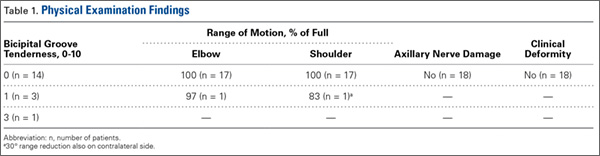
The clinical examination was performed a mean of 15.2 months (range, 12-26 months) after surgery. Physical examination findings are listed in Table 1.
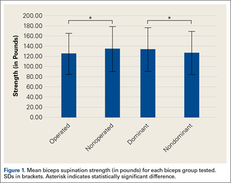
Forearm supination strength, averaged from 3 trials on each arm, was significantly (P = .01) greater in the nonoperated arm than in the operated arm (Table 2, Figure 1). A 95% confidence interval for the mean (SD) difference in strength was 9.35 (7.76) pounds, meaning that on average, the nonoperated arm will be 1.59 to 17.11 pounds stronger than the operated arm. In addition, strength of the dominant arm was greater than that of the nondominant arm (P = .05) regardless of which arm underwent surgery (Table 2, Figure 1). However, the mean (SD) difference in strength was 6.94 (8.39) pounds, indicating the observed difference was not statistically significant.
![]()
Sonographic Evaluation
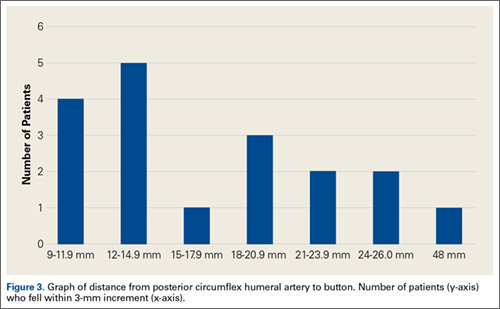
According to the sonographic evaluations, the tenodesis was intact in all 18 patients (Figure 2). Estimated mean (SD) distance from button to PCHA was 18.17 (9.0) mm (median, 16.1 mm; range, 9.4-48 mm) (Figure 2, Figure 3). No patient indicated any symptoms of AN damage.

Discussion
There are few studies of functional outcomes of biceps tenodesis. Pain is a common measure of patient satisfaction. Mazzocca and colleagues25 reported a mean follow-up pain score of 1.1 (range, 0.5-1.9) out of 10 for a group of 41 patients who had subpectoral tenodesis with an interference screw. Millett and colleagues26 reported a mean postoperative pain score of 2.5 out of 10 for patients who had subpectoral interference screw fixation. Our patients reported a mean pain score of 12.6 out of 100 after minimum 12-month follow-up. We also assessed for pain in the intertubercular groove during palpation. Although some studies have shown that groove pain was eliminated by subpectoral biceps tenodesis,5 3 patients in our study had pain on groove palpation. The cause of this residual pain is unclear, but some studies have suggested a chronic degenerative pathologic process that occurs while the tendon is within the biceps groove.27 Removing the tendon from the groove may not remove the underlying cause of pain.
Our patients’ mean DASH score was 15.15 (within the excellent range). Normative mean (SD) DASH score for the general population is 10.1 (14.68).28
Functional strength of forearm supination, shoulder ROM, and elbow ROM are objective measures of patient performance after fixation. On Cybex testing, Phillips and colleagues29 found no difference in forearm supination strength or elbow flexion (compared with contralateral arm) after biceps tenodesis or conservative treatment for proximal biceps ruptures. Shank and colleagues30 compared elbow flexion and supination strength of the affected and unaffected arms after suture anchor subpectoral biceps tenodesis. There was no significant difference in Cybex results, but there was a 14% to 15% loss of average strength in the tenodesed versus nonsurgical arm. In the present study, we found a significant difference in forearm supination strength between the operated and nonoperated arms, but with only a 7% loss of average strength in the operated arms. The difference in strength ranged from 1.59 to 17.11 pounds, which may not be clinically significant, as supination strength ranged from 60 to 270 pounds.
Of the 18 patients in this study, 9 had surgery on the dominant arm, and the other 9 had surgery on the nondominant arm. Examining the effect of arm dominance on results revealed that patients with surgery on the nondominant arm tended to have substantially reduced supination strength in that arm vs the dominant arm. There was an 11% loss of average strength for nondominant vs dominant arms that had surgery. Examining nondominant arms only revealed a 13% loss of strength for operated vs nonoperated arms. There was no difference in forearm supination strengths between nonoperated arms (dominant vs nondominant) or between dominant arms (operated vs nonoperated). This suggests that, though hand dominance may not play a significant role in control patients’ forearm supination strength,30 it may have a substantial effect on surgical patients’ ability to regain strength when the nondominant arm is the surgical arm. One objective of this study was to measure the distance between the biceps cortical button on the posterior humeral cortex and the AN/PCHA neurovascular bundle. The AN bundles with the PCHA posterior to the humeral neck.31-33 As the AN travels with the PCHA, and the PCHA has been reliably identified with Doppler ultrasonography,34-36 the PCHA was used as a marker for the AN in this study. Our bicortical button technique places the button on the posterior aspect of the humerus, making AN and PCHA the nearest at-risk neurovascular structures. None of our patients had symptoms of AN damage. However, 2 patients indicated pain in the posterior aspect of the humerus during deltoid activation. Distance from the neurovascular structures to the button was 48 mm in one patient and 13.6 mm in the other. DASH scores were 43 and 27, respectively. Both patients’ 1-year pain score was 30. The first patient underwent arthroscopic acromioplasty, distal clavicle resection, and microfracture of the glenoid surface in addition to the subpectoral biceps tenodesis; the second underwent subacromial decompression and distal clavicle resection in addition to the subpectoral biceps tenodesis. Whether the associated pathology contributed to their persistent pain is unknown. However, given the distance from AN/PCHA to button, it is unlikely that their pain was a result of neurovascular compromise from the procedure.
Advantages of the cortical button include the ability to drill a smaller hole in the humerus for fixation, compared with the hole drilled for an interference screw. Despite the biomechanical strength of the screw, large (8 mm) cortical violations have been associated with increased fracture risk of the proximal humerus.37,38 The tendon may experience less trauma than that caused by being twisted against an interference screw, the most common location of failure of which is the tendon–screw interface.39 In addition, tendon healing may be improved through circumferential healing in the cortical button tunnel.
A concern of using a bicortical button for fixation is drilling through the posterior cortex, because of the proximity of the posterior neurovascular structures. In a case in which the posterior cord was injured, Rhee and colleagues40 used a suture pullout technique whereby a Beath pin was passed out of the posterior humerus and soft tissues to then hold tension on the biceps tendon during the tenodesis. The radial nerve potentially could have been injured by pin overpenetration or by becoming wrapped up in the soft tissues as the pin was spinning through them. In our technique, the posterior humeral cortex is drilled cautiously to avoid overpenetration and possibly getting the posterior soft tissues wrapped up in the guide pin. No AN injuries have been reported with this technique. Mean distance from AN to posterior cortical button in this study was 18.17 mm. In 2 cadaver studies of bicortical drilling for subpectoral biceps tenodesis, the ANs were 25.1 mm and 36.7 mm from the posterior drill hole.41,21
Limitations of this study included its design (case series) and limited number of follow-up patients. Of the 28 consecutive patients identified for the study, 10 did not undergo the clinical examination, as they either lived more than 3 hours away (8 patients) or could not be contacted (2 patients). Another study limitation was the inability to directly image ANs with ultrasound. Therefore, measurements of the distance from the PCHA to the button were used to estimate the distance from the AN/PCHA neurovascular bundle to the button.
In this study, functional outcomes were excellent, and there were no tenodesis failures or neurovascular complications. These preliminary findings indicate that subpectoral biceps tenodesis with a bicortical button is a viable treatment option for patients with the appropriate indications for this procedure.
1. Khazzam M, George MS, Churchill RS, Kuhn JE. Disorders of the long head of biceps tendon. J Shoulder Elbow Surg. 2012;21(1):136-145.
2. Geaney LE, Mazzocca AD. Biceps brachii tendon ruptures: a review of diagnosis and treatment of proximal and distal biceps tendon ruptures. Phys Sportsmed. 2010;38(2):117-125.
3. Kelly AM, Drakos MC, Fealy S, Taylor SA, O’Brien SJ. Arthroscopic release of the long head of the biceps tendon: functional outcome and clinical results. Am J Sports Med. 2005;33(2):208-213.
4. Provencher MT, LeClere LE, Romeo AA. Subpectoral biceps tenodesis. Sports Med Arthrosc Rev. 2008;16(3):170-176.
5. Nho SJ, Reiff SN, Verma NN, Slabaugh MA, Mazzocca AD, Romeo AA. Complications associated with subpectoral biceps tenodesis: low rates of incidence following surgery. J Shoulder Elbow Surg. 2010;19(5):764-768.
6. Mazzocca AD, Bicos J, Santangelo S, Romeo AA, Arciero RA. The biomechanical evaluation of four fixation techniques for proximal biceps tenodesis. Arthroscopy. 2005;21(11):1296-1306.
7. Ozalay, M, Akpinar S, Karaeminogullari O, et al. Mechanical strength of four different biceps tenodesis techniques. Arthroscopy. 2005;21(8):992-998.
8. Golish RS, Caldwell PE, Miller MD, et al. Interference screw versus suture anchor fixation for subpectoral tenodesis of the proximal biceps tendon: a cadaveric study. Arthroscopy. 2008;24(10):1103-1108.
9. Richards DP, Burkhart SS. A biomechanical analysis of two biceps tenodesis fixation techniques. Arthroscopy. 2005;21(7):861-866.
10. Mazzocca AD, Rios CG, Romeo AA, Arciero RA. Subpectoral biceps tenodesis with interference screw fixation. Arthroscopy. 2005;21(7):896.
11. Wolf RS, Zheng N, Weichel D. Long head biceps tenotomy versus tenodesis: a cadaveric biomechanical analysis. Arthroscopy. 2005;21(2):182-185.
12. Snir N, Hamula M, Wolfson T, Laible C, Sherman O. Long head of the biceps tenodesis with cortical button technique. Arthrosc Tech. 2013;2(2):e95-e97.
13. Arora AS, Singh A, Koonce RC. Biomechanical evaluation of a unicortical button versus interference screw for subpectoral biceps tenodesis. Arthroscopy. 2013;29(4):638-644.
14. Buchholz A, Martetschläger F, Siebenlist S, et al. Biomechanical comparison of intramedullary cortical button fixation and interference screw technique for subpectoral biceps tenodesis. Arthroscopy. 2013;29(5):845-853.
15. Bain GI, Prem H, Heptinstall RJ, Verhellen R, Paix D. Repair of distal biceps tendon rupture: a new technique using the Endobutton. J Shoulder Elbow Surg. 2000;9(2):120-126.
16. Greenberg JA. Endobutton repair of distal biceps tendon ruptures. J Hand Surg Am. 2009;34(8):1541-1548.
17. Heinzelmann AD, Savoie FH 3rd, Ramsey JR, Field LD, Mazzocca AD. A combined technique for distal biceps repair using a soft tissue button and biotenodesis interference screw. Am J Sports Med. 2009;37(5):989-994.
18. DeAngelis JP, Chen A, Wexler M, et al. Biomechanical characterization of unicortical button fixation: a novel technique for proximal subpectoral biceps tenodesis. Knee Surg Sports Traumatol Arthrosc. 2015;23(5):1434-1441.
19. Dickens JF, Kilcoyne KG, Tintle SM, Giuliani J, Schaefer RA, Rue JP. Subpectoral biceps tenodesis: an anatomic study and evaluation of at-risk structures. Am J Sports Med. 2012;40(10):2337-2341.
20. Sethi PM, Rajaram A, Beitzel K, Hackett TR, Chowaniec DM, Mazzocca AD. Biomechanical performance of subpectoral biceps tenodesis: a comparison of interference screw fixation, cortical button fixation, and interference screw diameter. J Shoulder Elbow Surg. 2013;22(4):451-457.
21. Sethi PM, Vadasdi K, Greene RT, Vitale MA, Duong M, Miller SR. Safety of open suprapectoral and subpectoral biceps tenodesis: an anatomic assessment of risk for neurologic injury. J Shoulder Elbow Surg. 2015;24(1):138-142.
22. Gummesson C, Ward MM, Atroshi I. The shortened Disabilities of the Arm, Shoulder and Hand questionnaire (QuickDASH): validity and reliability based on responses within the full-length DASH. BMC Musculoskelet Disord. 2006;7:44.
23. Schmidt CC, Brown BT, Sawardeker PJ, DeGravelle M Jr, Miller MC. Factors affecting supination strength after a distal biceps rupture. J Shoulder Elbow Surg. 2014;23(1):68-75.
24. Brotzman SB, Wilk KE, eds. Handbook of Orthopaedic Rehabilitation. Philadelphia, PA: Mosby Elsevier; 2007.
25. Mazzocca AD, Cote MP, Arciero CL, Romeo AA, Arciero RA. Clinical outcomes after subpectoral biceps tenodesis with an interference screw. Am J Sports Med. 2008;36(10):1922-1929.
26. Millett PJ, Snaders B, Gobezie R, Braun S, Warner JP. Interference screw versus suture anchor fixation for open subpectoral biceps tenodesis: does it matter? BMC Musculoskelet Disord. 2008;9(121):1-6.
27. Streit JJ, Shishani Y, Rodgers M, Gobezie R. Tendinopathy of the long head of the biceps tendon: histopathologic analysis of the extra-articular biceps tendon and tenosynovium. Open Access J Sports Med. 2015;6:63-70.
28. Hunsaker FG, Cioffi DA, Amadio PC, Wright JG, Caughlin B. The American Academy of Orthopaedic Surgeons outcomes instruments: normative values from the general population. J Bone Joint Surg Am. 2002;84(2):208-215.
29. Phillips BB, Canale ST, Sisk TD, Stralka SW, Wyatt KP. Rupture of the proximal biceps tendon in middle-aged patients. Orthop Rev. 1993;22(3):349-353.
30. Shank JR, Singleton SB, Braun S, et al. A comparison of forearm supination and elbow flexion strength in patients with long head of the biceps tenotomy or tenodesis. Arthroscopy. 2011;27(1):9-16.
31. Apaydin N, Tubbs RS, Loukas M, Duparc F. Review of the surgical anatomy of the axillary nerve and the anatomic basis of its iatrogenic and traumatic injury. Surg Radiol Anat. 2010;32(3):193-201.
32. Johnson D. Pectoral girdle and upper limp. In: Standring S, ed. Gray’s Anatomy. 40th ed. New York, NY: Elsevier; 2008:814-821.
33. Tubbs RS, Tyler-Kabara EC, Aikens AC, et al. Surgical anatomy of the axillary nerve within the quadrangular space. J Neurosurg. 2005;102(5):912-914.
34. Kim YA, Yoon KB, Kwon TD, Kim DH, Yoon DM. Evaluation of anatomic landmarks for axillary nerve block in the quadrilateral space. Acta Anaesthesiol Scand. 2014;58(5):567-571.
35. Robinson DJ, Marks P, Schneider-Kolsky ME. Ultrasound of the posterior circumflex humeral artery. J Med Imaging Radiat Oncol. 2010;54(3):219-223.
36. Rothe C, Asghar S, Andersen HL, Christensen JK, Lange KH. Ultrasound-guided block of the axillary nerve: a volunteer study of a new method. Acta Anaesthesiol Scand. 2011;55(5):565-570.
37. Reiff SN, Nho SJ, Romeo AA. Proximal humerus fracture after keyhole biceps tenodesis. Am J Orthop. 2010;39(7):E61-E63.
38. Sears BW, Spencer EE, Getz CL. Humeral fracture following subpectoral biceps tenodesis in 2 active, healthy patients. J Shoulder Elbow Surg. 2011;20(6):e7-e11.
39. Koch BS, Burks RT. Failure of biceps tenodesis with interference screw fixation. Arthroscopy. 2012;28(5):735-740.
40. Rhee PC, Spinner RJ, Bishop AT, Shin AY. Iatrogenic brachial plexus injuries associated with open subpectoral biceps tenodesis. Am J Sports Med. 2013;41(9):2048-2053.
41. Ding DY, Gupta A, Snir N, Wolfson T, Meislin RJ. Nerve proximity during bicortical drilling for subpectoral biceps tenodesis: a cadaveric study. Arthroscopy. 2014;30(8):942-946.
The long head of the biceps (LHB) tendon is a recognized source of shoulder pain. LHB tendon pathology is commonly associated with other shoulder conditions, such as superior labral tears, rotator cuff tears, or subacromial impingement, whereas isolated pathology, such as traumatic ruptures, tendinosis, or medial subluxation, is rare.1 Treatment of LHB pathology ranges from conservative measures to surgical measures, including tenotomy or tenodesis.2 LHB tenodesis offers the advantage of maintaining the length–tension relationship of the biceps muscle to prevent atrophy and avoid the Popeye deformity incurred from tenotomy alone. Tenodesis also prevents muscle cramping associated with contracted biceps muscle and better maintains elbow flexion and supination strength, which may be decreased with tenotomy.3 In addition, when a subpectoral biceps tenodesis technique is used, pain from LHB tendinopathy in the intertubercular groove may be reduced.4
Open subpectoral biceps tenodesis is a reproducible, efficient method for LHB tenodesis.4,5 A variety of fixation devices has been used: bone tunnels,6 keyhole fixation,7 suture anchors,6-9 and interference screws.6-8,10,11 More recently, a bicortical button has been used for LHB tendon tenodesis.12 Biomechanical studies have shown that load to failure is comparable for bicortical button fixation and interference screw fixation.13,14 In other models of tendon repair, the bicortical button has strength and stability comparable to those of interference screw fixation and enables earlier rehabilitation.15-17 However, there is concern that bicortical button fixation may result in axillary nerve (AN) or posterior circumflex humeral artery (PCHA) compromise because of the proximity of these neurovascular structures to the bicortical button.13,18-21
We conducted a study to functionally and sonographically assess the outcomes of patients who underwent open subpectoral biceps tenodesis with a bicortical button. Functional outcomes were assessed with patient-reported outcomes and physician-reported outcomes. Sonographic studies were used to evaluate the integrity of the tenodesis and determine the proximity of the button to the AN and the PCHA along the posterior proximal humerus.
Methods
After obtaining Institutional Review Board approval for this study, we retrospectively identified 28 consecutive patients who had proximal biceps tenodesis performed by a single surgeon (Dr. K.E. Swanson) using a mini-open subpectoral biceps tenodesis technique with a bicortical button between March 2011 and January 2013. All 28 patients were asked to participate in the study. Twenty-four (86%) agreed to complete 2 surgical outcome surveys, and 18 (64%) completed a 3-part clinical examination at minimum 12-month follow-up.
One of the surveys was Quick Disabilities of the Arm, Shoulder, and Hand (QuickDASH), a validated comprehensive disability survey that scores upper extremity functionality on a scale ranging from 0 (none) to 100 (extreme difficulty).22,23 The other survey scored pain on a scale ranging from 0 (none) to 100 (worst pain).
The clinical examination was completed during a single visit by an orthopedic surgeon (Dr. Meadows or Dr. Diesselhorst) different from the primary surgeon (Dr. K.E. Swanson) and by a clinician-sonologist (Dr. Finnoff). The examination’s 3 parts were physical examination of arm, biceps supination strength test, and ultrasonographic evaluation.
Physical Examination of Arm. Physical examination included palpation of bicipital groove, range of motion (ROM) of shoulder and elbow, and clinical deformity of biceps. Patients were questioned regarding symptoms of AN damage, including sensory and motor findings. Bicipital groove tenderness was assessed with a visual analog scale rating pain 0 to 10. ROM was measured in degrees and was presented as a percentage of full elbow ROM (150°) and full shoulder ROM (180°).
Biceps Supination Strength Test. Biceps supination strength was tested with a baseline hydraulic wrist dynamometer with door handle attachment. Patients were seated with the elbow bent 90° and the forearm in a neutral position. In a series of 3 trials, the patient maintained grip of the dynamometer doorknob while supinating the forearm. The tenodesed (operated) arm and contralateral unaffected (nonoperated) arm were tested in random order and recorded in pounds.
Ultrasonographic Evaluation. Ultrasonography was used to evaluate the tenodesis site. In each case, the biceps tendon was assessed to determine the location of the bicortical button in relation to the AN/PCHA neurovascular bundle. Whereas nerves are difficult to visualize with ultrasonography, arteries are readily seen. Dr. Finnoff used a CX50 ultrasound machine (Philips Medical Systems) with either a 12-3 MHz linear array or a 5-1 MHz curvilinear array transducer to measure the shortest distance from the PCHA to the button.
Each patient was placed in a lateral decubitus or prone position, and the skin of the upper arm was exposed. Tendon integrity was deemed either intact (continuity between biceps tendon and cortical button) or disrupted (lack of continuity between tendon and cortical button). The transducer was then placed in an anatomical sagittal plane over the posterior aspect of the proximal humerus. Power Doppler and cephalad and caudad transducer glides were used to identify the location of the PCHA. The transducer was then glided laterally and anteriorly around the humerus, following the course of the PCHA, until the cortical button was located. The narrowest interval between the PCHA and the cortical button was measured using the ultrasound machine’s software. A still image of each measurement was saved.
Surgical Technique
Biceps tenodesis indications included high-demand heavy laborers, athletes, and patients who preferred the cosmetic results of tenodesis over tenotomy. Most patients had acute symptomatic tears of the superior labrum with instability of the biceps anchor complex. Others had fraying and tenosynovitis of the LHB tendon. Any associated pathology was addressed during the same surgical period.
The surgical technique used was similar to that described by Snir and colleagues.12 Each patient was placed in the lateral decubitus position. Once pathology confirmed biceps tenodesis, the biceps tendon was tenotomized at the base of the superior labrum. A 3-cm incision was made along the axillary fold centered over the inferior border of the pectoralis major tendon. Blunt dissection was performed to define the inferior border of the pectoralis major tendon and to palpate the underlying biceps tendon as it exited the intertubercular groove. The LHB tendon was removed and prepared with No. 2 Fiberwire (Arthrex) in Krackow fashion starting 2 cm proximal to the musculotendinous junction. The excess tendon was excised.
A 3.2-mm guide wire was centered along the most distal aspect of the biceps groove and then drilled through the anterior cortex and just through the posterior cortex. A cannulated reamer, selected on the basis of the biceps tendon diameter (typically, 5-7 mm), was then drilled over the guide wire through the anterior cortex only. The Food and Drug Administration–approved cortical button (BicepsButton; Arthrex) was then loaded by passing the tendon suture ends through each side of the button in alternating fashion, thus allowing the button to slide along the sutures.
The button was loaded onto the BicepsButton deployment device and inserted through the drilled tunnel of the anterior cortex and just through the posterior cortex. The deployment device was then removed, and 1 suture end was pulled to allow the button to engage the posterior humeral cortex. Pulling on both sutures allowed the biceps tendon to slide through the anterior cortex hole of the humerus until the tendon reached the posterior humeral cortex. Tension was verified, and the sutures were tied over the tendon. The wound was then irrigated and closed.
Rehabilitation Program
Patients completed a standard rehabilitation protocol for biceps tenodesis24 along with rehabilitation protocols for any additional procedures performed. In phase 1 (weeks 0-2), they focused on gradual restoration of passive ROM and remained in a sling. In phase 2 (weeks 2-6), they focused on gradual restoration of active ROM, and by week 3 were weaned out of the sling. In phase 3 (weeks 6-8), they continued ROM and strengthening exercises to normalize strength, endurance, and neuromuscular control. In phase 4 (weeks 8-12), they focused on advanced strengthening exercises and return to activities.
Statistical Analysis
Descriptive statistics included means, medians, and SDs. Comparisons between operated and nonoperated arms and between dominant and nondominant arms were performed by a statistician using paired t tests with P = .05. Confidence intervals were calculated for operated and nonoperated arms and for dominant and nondominant arms by using the differences between them.
Results
Functional Outcomes
Surgical outcome scores and pain scores were obtained from 24 patients (86%) at minimum 12-month follow-up. Mean (SD) DASH score was 15.15 (17.6; median, 9), and mean (median) pain score was 12.61 (7).
Eighteen patients (64%) completed the clinical examination: 16 men (88.9%) and 2 women (11.1%). Mean age was 48.3 years (age range, 33-59 years). Of these 18 patients, 9 (50%) had surgery on the dominant arm, and the other 9 had surgery on the nondominant arm. All patients were right-hand–dominant. In 3 patients, biceps tenodesis was performed with only minimal arthroscopic débridement (20%); in the other 15, biceps tenodesis was performed concomitantly with 1 or more additional arthroscopic procedures: acromioplasty (73%), rotator cuff repair (47%), distal clavicle resection (33%), subacromial bursectomy (13%), microfracture of glenoid (13%), and posterior labral repair (7%).
The clinical examination was performed a mean of 15.2 months (range, 12-26 months) after surgery. Physical examination findings are listed in Table 1.
Forearm supination strength, averaged from 3 trials on each arm, was significantly (P = .01) greater in the nonoperated arm than in the operated arm (Table 2, Figure 1). A 95% confidence interval for the mean (SD) difference in strength was 9.35 (7.76) pounds, meaning that on average, the nonoperated arm will be 1.59 to 17.11 pounds stronger than the operated arm. In addition, strength of the dominant arm was greater than that of the nondominant arm (P = .05) regardless of which arm underwent surgery (Table 2, Figure 1). However, the mean (SD) difference in strength was 6.94 (8.39) pounds, indicating the observed difference was not statistically significant.
![]()
Sonographic Evaluation
According to the sonographic evaluations, the tenodesis was intact in all 18 patients (Figure 2). Estimated mean (SD) distance from button to PCHA was 18.17 (9.0) mm (median, 16.1 mm; range, 9.4-48 mm) (Figure 2, Figure 3). No patient indicated any symptoms of AN damage.
Discussion
There are few studies of functional outcomes of biceps tenodesis. Pain is a common measure of patient satisfaction. Mazzocca and colleagues25 reported a mean follow-up pain score of 1.1 (range, 0.5-1.9) out of 10 for a group of 41 patients who had subpectoral tenodesis with an interference screw. Millett and colleagues26 reported a mean postoperative pain score of 2.5 out of 10 for patients who had subpectoral interference screw fixation. Our patients reported a mean pain score of 12.6 out of 100 after minimum 12-month follow-up. We also assessed for pain in the intertubercular groove during palpation. Although some studies have shown that groove pain was eliminated by subpectoral biceps tenodesis,5 3 patients in our study had pain on groove palpation. The cause of this residual pain is unclear, but some studies have suggested a chronic degenerative pathologic process that occurs while the tendon is within the biceps groove.27 Removing the tendon from the groove may not remove the underlying cause of pain.
Our patients’ mean DASH score was 15.15 (within the excellent range). Normative mean (SD) DASH score for the general population is 10.1 (14.68).28
Functional strength of forearm supination, shoulder ROM, and elbow ROM are objective measures of patient performance after fixation. On Cybex testing, Phillips and colleagues29 found no difference in forearm supination strength or elbow flexion (compared with contralateral arm) after biceps tenodesis or conservative treatment for proximal biceps ruptures. Shank and colleagues30 compared elbow flexion and supination strength of the affected and unaffected arms after suture anchor subpectoral biceps tenodesis. There was no significant difference in Cybex results, but there was a 14% to 15% loss of average strength in the tenodesed versus nonsurgical arm. In the present study, we found a significant difference in forearm supination strength between the operated and nonoperated arms, but with only a 7% loss of average strength in the operated arms. The difference in strength ranged from 1.59 to 17.11 pounds, which may not be clinically significant, as supination strength ranged from 60 to 270 pounds.
Of the 18 patients in this study, 9 had surgery on the dominant arm, and the other 9 had surgery on the nondominant arm. Examining the effect of arm dominance on results revealed that patients with surgery on the nondominant arm tended to have substantially reduced supination strength in that arm vs the dominant arm. There was an 11% loss of average strength for nondominant vs dominant arms that had surgery. Examining nondominant arms only revealed a 13% loss of strength for operated vs nonoperated arms. There was no difference in forearm supination strengths between nonoperated arms (dominant vs nondominant) or between dominant arms (operated vs nonoperated). This suggests that, though hand dominance may not play a significant role in control patients’ forearm supination strength,30 it may have a substantial effect on surgical patients’ ability to regain strength when the nondominant arm is the surgical arm. One objective of this study was to measure the distance between the biceps cortical button on the posterior humeral cortex and the AN/PCHA neurovascular bundle. The AN bundles with the PCHA posterior to the humeral neck.31-33 As the AN travels with the PCHA, and the PCHA has been reliably identified with Doppler ultrasonography,34-36 the PCHA was used as a marker for the AN in this study. Our bicortical button technique places the button on the posterior aspect of the humerus, making AN and PCHA the nearest at-risk neurovascular structures. None of our patients had symptoms of AN damage. However, 2 patients indicated pain in the posterior aspect of the humerus during deltoid activation. Distance from the neurovascular structures to the button was 48 mm in one patient and 13.6 mm in the other. DASH scores were 43 and 27, respectively. Both patients’ 1-year pain score was 30. The first patient underwent arthroscopic acromioplasty, distal clavicle resection, and microfracture of the glenoid surface in addition to the subpectoral biceps tenodesis; the second underwent subacromial decompression and distal clavicle resection in addition to the subpectoral biceps tenodesis. Whether the associated pathology contributed to their persistent pain is unknown. However, given the distance from AN/PCHA to button, it is unlikely that their pain was a result of neurovascular compromise from the procedure.
Advantages of the cortical button include the ability to drill a smaller hole in the humerus for fixation, compared with the hole drilled for an interference screw. Despite the biomechanical strength of the screw, large (8 mm) cortical violations have been associated with increased fracture risk of the proximal humerus.37,38 The tendon may experience less trauma than that caused by being twisted against an interference screw, the most common location of failure of which is the tendon–screw interface.39 In addition, tendon healing may be improved through circumferential healing in the cortical button tunnel.
A concern of using a bicortical button for fixation is drilling through the posterior cortex, because of the proximity of the posterior neurovascular structures. In a case in which the posterior cord was injured, Rhee and colleagues40 used a suture pullout technique whereby a Beath pin was passed out of the posterior humerus and soft tissues to then hold tension on the biceps tendon during the tenodesis. The radial nerve potentially could have been injured by pin overpenetration or by becoming wrapped up in the soft tissues as the pin was spinning through them. In our technique, the posterior humeral cortex is drilled cautiously to avoid overpenetration and possibly getting the posterior soft tissues wrapped up in the guide pin. No AN injuries have been reported with this technique. Mean distance from AN to posterior cortical button in this study was 18.17 mm. In 2 cadaver studies of bicortical drilling for subpectoral biceps tenodesis, the ANs were 25.1 mm and 36.7 mm from the posterior drill hole.41,21
Limitations of this study included its design (case series) and limited number of follow-up patients. Of the 28 consecutive patients identified for the study, 10 did not undergo the clinical examination, as they either lived more than 3 hours away (8 patients) or could not be contacted (2 patients). Another study limitation was the inability to directly image ANs with ultrasound. Therefore, measurements of the distance from the PCHA to the button were used to estimate the distance from the AN/PCHA neurovascular bundle to the button.
In this study, functional outcomes were excellent, and there were no tenodesis failures or neurovascular complications. These preliminary findings indicate that subpectoral biceps tenodesis with a bicortical button is a viable treatment option for patients with the appropriate indications for this procedure.
1. Khazzam M, George MS, Churchill RS, Kuhn JE. Disorders of the long head of biceps tendon. J Shoulder Elbow Surg. 2012;21(1):136-145.
2. Geaney LE, Mazzocca AD. Biceps brachii tendon ruptures: a review of diagnosis and treatment of proximal and distal biceps tendon ruptures. Phys Sportsmed. 2010;38(2):117-125.
3. Kelly AM, Drakos MC, Fealy S, Taylor SA, O’Brien SJ. Arthroscopic release of the long head of the biceps tendon: functional outcome and clinical results. Am J Sports Med. 2005;33(2):208-213.
4. Provencher MT, LeClere LE, Romeo AA. Subpectoral biceps tenodesis. Sports Med Arthrosc Rev. 2008;16(3):170-176.
5. Nho SJ, Reiff SN, Verma NN, Slabaugh MA, Mazzocca AD, Romeo AA. Complications associated with subpectoral biceps tenodesis: low rates of incidence following surgery. J Shoulder Elbow Surg. 2010;19(5):764-768.
6. Mazzocca AD, Bicos J, Santangelo S, Romeo AA, Arciero RA. The biomechanical evaluation of four fixation techniques for proximal biceps tenodesis. Arthroscopy. 2005;21(11):1296-1306.
7. Ozalay, M, Akpinar S, Karaeminogullari O, et al. Mechanical strength of four different biceps tenodesis techniques. Arthroscopy. 2005;21(8):992-998.
8. Golish RS, Caldwell PE, Miller MD, et al. Interference screw versus suture anchor fixation for subpectoral tenodesis of the proximal biceps tendon: a cadaveric study. Arthroscopy. 2008;24(10):1103-1108.
9. Richards DP, Burkhart SS. A biomechanical analysis of two biceps tenodesis fixation techniques. Arthroscopy. 2005;21(7):861-866.
10. Mazzocca AD, Rios CG, Romeo AA, Arciero RA. Subpectoral biceps tenodesis with interference screw fixation. Arthroscopy. 2005;21(7):896.
11. Wolf RS, Zheng N, Weichel D. Long head biceps tenotomy versus tenodesis: a cadaveric biomechanical analysis. Arthroscopy. 2005;21(2):182-185.
12. Snir N, Hamula M, Wolfson T, Laible C, Sherman O. Long head of the biceps tenodesis with cortical button technique. Arthrosc Tech. 2013;2(2):e95-e97.
13. Arora AS, Singh A, Koonce RC. Biomechanical evaluation of a unicortical button versus interference screw for subpectoral biceps tenodesis. Arthroscopy. 2013;29(4):638-644.
14. Buchholz A, Martetschläger F, Siebenlist S, et al. Biomechanical comparison of intramedullary cortical button fixation and interference screw technique for subpectoral biceps tenodesis. Arthroscopy. 2013;29(5):845-853.
15. Bain GI, Prem H, Heptinstall RJ, Verhellen R, Paix D. Repair of distal biceps tendon rupture: a new technique using the Endobutton. J Shoulder Elbow Surg. 2000;9(2):120-126.
16. Greenberg JA. Endobutton repair of distal biceps tendon ruptures. J Hand Surg Am. 2009;34(8):1541-1548.
17. Heinzelmann AD, Savoie FH 3rd, Ramsey JR, Field LD, Mazzocca AD. A combined technique for distal biceps repair using a soft tissue button and biotenodesis interference screw. Am J Sports Med. 2009;37(5):989-994.
18. DeAngelis JP, Chen A, Wexler M, et al. Biomechanical characterization of unicortical button fixation: a novel technique for proximal subpectoral biceps tenodesis. Knee Surg Sports Traumatol Arthrosc. 2015;23(5):1434-1441.
19. Dickens JF, Kilcoyne KG, Tintle SM, Giuliani J, Schaefer RA, Rue JP. Subpectoral biceps tenodesis: an anatomic study and evaluation of at-risk structures. Am J Sports Med. 2012;40(10):2337-2341.
20. Sethi PM, Rajaram A, Beitzel K, Hackett TR, Chowaniec DM, Mazzocca AD. Biomechanical performance of subpectoral biceps tenodesis: a comparison of interference screw fixation, cortical button fixation, and interference screw diameter. J Shoulder Elbow Surg. 2013;22(4):451-457.
21. Sethi PM, Vadasdi K, Greene RT, Vitale MA, Duong M, Miller SR. Safety of open suprapectoral and subpectoral biceps tenodesis: an anatomic assessment of risk for neurologic injury. J Shoulder Elbow Surg. 2015;24(1):138-142.
22. Gummesson C, Ward MM, Atroshi I. The shortened Disabilities of the Arm, Shoulder and Hand questionnaire (QuickDASH): validity and reliability based on responses within the full-length DASH. BMC Musculoskelet Disord. 2006;7:44.
23. Schmidt CC, Brown BT, Sawardeker PJ, DeGravelle M Jr, Miller MC. Factors affecting supination strength after a distal biceps rupture. J Shoulder Elbow Surg. 2014;23(1):68-75.
24. Brotzman SB, Wilk KE, eds. Handbook of Orthopaedic Rehabilitation. Philadelphia, PA: Mosby Elsevier; 2007.
25. Mazzocca AD, Cote MP, Arciero CL, Romeo AA, Arciero RA. Clinical outcomes after subpectoral biceps tenodesis with an interference screw. Am J Sports Med. 2008;36(10):1922-1929.
26. Millett PJ, Snaders B, Gobezie R, Braun S, Warner JP. Interference screw versus suture anchor fixation for open subpectoral biceps tenodesis: does it matter? BMC Musculoskelet Disord. 2008;9(121):1-6.
27. Streit JJ, Shishani Y, Rodgers M, Gobezie R. Tendinopathy of the long head of the biceps tendon: histopathologic analysis of the extra-articular biceps tendon and tenosynovium. Open Access J Sports Med. 2015;6:63-70.
28. Hunsaker FG, Cioffi DA, Amadio PC, Wright JG, Caughlin B. The American Academy of Orthopaedic Surgeons outcomes instruments: normative values from the general population. J Bone Joint Surg Am. 2002;84(2):208-215.
29. Phillips BB, Canale ST, Sisk TD, Stralka SW, Wyatt KP. Rupture of the proximal biceps tendon in middle-aged patients. Orthop Rev. 1993;22(3):349-353.
30. Shank JR, Singleton SB, Braun S, et al. A comparison of forearm supination and elbow flexion strength in patients with long head of the biceps tenotomy or tenodesis. Arthroscopy. 2011;27(1):9-16.
31. Apaydin N, Tubbs RS, Loukas M, Duparc F. Review of the surgical anatomy of the axillary nerve and the anatomic basis of its iatrogenic and traumatic injury. Surg Radiol Anat. 2010;32(3):193-201.
32. Johnson D. Pectoral girdle and upper limp. In: Standring S, ed. Gray’s Anatomy. 40th ed. New York, NY: Elsevier; 2008:814-821.
33. Tubbs RS, Tyler-Kabara EC, Aikens AC, et al. Surgical anatomy of the axillary nerve within the quadrangular space. J Neurosurg. 2005;102(5):912-914.
34. Kim YA, Yoon KB, Kwon TD, Kim DH, Yoon DM. Evaluation of anatomic landmarks for axillary nerve block in the quadrilateral space. Acta Anaesthesiol Scand. 2014;58(5):567-571.
35. Robinson DJ, Marks P, Schneider-Kolsky ME. Ultrasound of the posterior circumflex humeral artery. J Med Imaging Radiat Oncol. 2010;54(3):219-223.
36. Rothe C, Asghar S, Andersen HL, Christensen JK, Lange KH. Ultrasound-guided block of the axillary nerve: a volunteer study of a new method. Acta Anaesthesiol Scand. 2011;55(5):565-570.
37. Reiff SN, Nho SJ, Romeo AA. Proximal humerus fracture after keyhole biceps tenodesis. Am J Orthop. 2010;39(7):E61-E63.
38. Sears BW, Spencer EE, Getz CL. Humeral fracture following subpectoral biceps tenodesis in 2 active, healthy patients. J Shoulder Elbow Surg. 2011;20(6):e7-e11.
39. Koch BS, Burks RT. Failure of biceps tenodesis with interference screw fixation. Arthroscopy. 2012;28(5):735-740.
40. Rhee PC, Spinner RJ, Bishop AT, Shin AY. Iatrogenic brachial plexus injuries associated with open subpectoral biceps tenodesis. Am J Sports Med. 2013;41(9):2048-2053.
41. Ding DY, Gupta A, Snir N, Wolfson T, Meislin RJ. Nerve proximity during bicortical drilling for subpectoral biceps tenodesis: a cadaveric study. Arthroscopy. 2014;30(8):942-946.
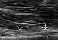
Emergency Imaging: Shortness of breath
A 79-year-old woman presented to the ED with acute shortness of breath. Of note, she had been recently discharged from our hospital after an open reduction and internal fixation of an intertrochanteric fracture of the right hip. The patient’s postoperative course was uncomplicated, and she was discharged home after a brief inpatient stay.
On physical examination, the patient was diaphoretic and tachypneic; oxygen saturation was 68% on room air, but increased to 100% saturation with supplemental oxygen through a nonrebreather mask. Radiographs from the patient’s inpatient hospital stay (Figure 1a) as well as ED visit (Figure 1b) were reviewed; representative images are shown above.
What is the diagnosis? What additional imaging tests may be useful to confirm the diagnosis?
Answer
The radiographs taken at the time of the patient’s discharge were normal. The radiograph of the chest obtained in the ED, however, demonstrated a distinct cut-off of the right mainstem bronchus, referred to as a bronchial cut-off sign (white arrow, Figure 2), with a rounded density projecting over the right mainstem bronchus (white asterisk, Figure 2). These radiographic appearances suggested the presence of an aspirated foreign body.
A computed tomography (CT) scan of the chest with contrast was performed to further evaluate the radiographic opacity and to exclude pulmonary embolism (PE), as this patient was at risk for such. The CT scan revealed no evidence of PE but confirmed the diagnosis of an aspirated foreign body. A high-density tablet (black asterisk, Figure 3) was noted to be completely occluding the right mainstem bronchus (white arrow, Figure 3) with resultant mild hyperinflation of the right lung. Upon further questioning, the patient stated that she had choked on a calcium tablet earlier in the day, but thought that the pill had finally “gone down.”
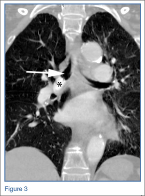
Since aspiration of foreign bodies is far more common in children,1,2 the diagnosis often is not considered in adults who present with acute onset of shortness of breath. In adults, the most significant predisposing factor to aspiration is alcoholism. However, foreign body aspiration may arise in various clinical scenarios, including in patients with structural abnormalities, in those with neuromuscular disease, and in the postoperative setting. The most common aspirated foreign bodies are food and broken tooth fragments/periodontal devices (eg, periodontal splint).2
Presentation is varied and depends upon the nature and volume of the aspirated foreign body, which may contribute to the airway obstruction or an inflammatory bronchopneumonia. The posterior segment of the upper lobes and the superior segments of the lower lobes are the most commonly involved sites, with the right lung preferentially involved over the left lung.3
The diagnosis of foreign body aspiration begins with an appropriate clinical history. Given our patient’s recent orthopedic surgery, PE was an understandable diagnostic consideration. As with any patient acutely short of breath, radiographs are the initial diagnostic imaging study of choice. An abrupt truncation of a bronchus on radiography suggests obstruction related to a mucous plugging, cancer, or foreign body aspiration. Other findings of foreign body aspiration include segmental/lobar hyperinflation and/or atelectasis.3 In many scenarios, the aspirated foreign body may not be radiodense, which limits the utility and diagnostic accuracy of radiography. Computed tomography improves diagnostic precision and time to diagnosis by directly visualizing the airway lumen and improving visualization of radiolucent objects.4
Treatment for obstructive aspiration depends upon the location and nature of the aspirated object. However, bedside bronchoscopy and extraction of the foreign object is the mainstay of treatment, and is how this patient was treated. Rapid diagnosis and treatment is key to alleviating obstruction and preventing potential complications of hemoptysis and infection.
1. Marom EM, McAdams HP, Erasmus JJ, Goodman PC. The many faces of pulmonary aspiration. AJR Am J Roentgenol. 1999;172(1):121-128.
2. McGuirt WF, Holmes KD, Feehs R, Browne JD. Tracheobronchial foreign bodies. Laryngoscope. 1988;98(6 Pt 1):615-618.
3. Franquet T, Giménez A, Rosón N, Torrubia S, Sabaté JM, Pérez C. Aspiration diseases: Findings, pitfalls, and differential diagnosis. Radiographics. 2000;20(3):673-685.
4. Newton JP, Abel RW, Lloyd CH, Yemm R. The use of computed tomography in the detection of radiolucent denture base material in the chest. J Oral Rehabil. 1987;14(2):193-202.
A 79-year-old woman presented to the ED with acute shortness of breath. Of note, she had been recently discharged from our hospital after an open reduction and internal fixation of an intertrochanteric fracture of the right hip. The patient’s postoperative course was uncomplicated, and she was discharged home after a brief inpatient stay.
On physical examination, the patient was diaphoretic and tachypneic; oxygen saturation was 68% on room air, but increased to 100% saturation with supplemental oxygen through a nonrebreather mask. Radiographs from the patient’s inpatient hospital stay (Figure 1a) as well as ED visit (Figure 1b) were reviewed; representative images are shown above.
What is the diagnosis? What additional imaging tests may be useful to confirm the diagnosis?
Answer
The radiographs taken at the time of the patient’s discharge were normal. The radiograph of the chest obtained in the ED, however, demonstrated a distinct cut-off of the right mainstem bronchus, referred to as a bronchial cut-off sign (white arrow, Figure 2), with a rounded density projecting over the right mainstem bronchus (white asterisk, Figure 2). These radiographic appearances suggested the presence of an aspirated foreign body.
A computed tomography (CT) scan of the chest with contrast was performed to further evaluate the radiographic opacity and to exclude pulmonary embolism (PE), as this patient was at risk for such. The CT scan revealed no evidence of PE but confirmed the diagnosis of an aspirated foreign body. A high-density tablet (black asterisk, Figure 3) was noted to be completely occluding the right mainstem bronchus (white arrow, Figure 3) with resultant mild hyperinflation of the right lung. Upon further questioning, the patient stated that she had choked on a calcium tablet earlier in the day, but thought that the pill had finally “gone down.”
Since aspiration of foreign bodies is far more common in children,1,2 the diagnosis often is not considered in adults who present with acute onset of shortness of breath. In adults, the most significant predisposing factor to aspiration is alcoholism. However, foreign body aspiration may arise in various clinical scenarios, including in patients with structural abnormalities, in those with neuromuscular disease, and in the postoperative setting. The most common aspirated foreign bodies are food and broken tooth fragments/periodontal devices (eg, periodontal splint).2
Presentation is varied and depends upon the nature and volume of the aspirated foreign body, which may contribute to the airway obstruction or an inflammatory bronchopneumonia. The posterior segment of the upper lobes and the superior segments of the lower lobes are the most commonly involved sites, with the right lung preferentially involved over the left lung.3
The diagnosis of foreign body aspiration begins with an appropriate clinical history. Given our patient’s recent orthopedic surgery, PE was an understandable diagnostic consideration. As with any patient acutely short of breath, radiographs are the initial diagnostic imaging study of choice. An abrupt truncation of a bronchus on radiography suggests obstruction related to a mucous plugging, cancer, or foreign body aspiration. Other findings of foreign body aspiration include segmental/lobar hyperinflation and/or atelectasis.3 In many scenarios, the aspirated foreign body may not be radiodense, which limits the utility and diagnostic accuracy of radiography. Computed tomography improves diagnostic precision and time to diagnosis by directly visualizing the airway lumen and improving visualization of radiolucent objects.4
Treatment for obstructive aspiration depends upon the location and nature of the aspirated object. However, bedside bronchoscopy and extraction of the foreign object is the mainstay of treatment, and is how this patient was treated. Rapid diagnosis and treatment is key to alleviating obstruction and preventing potential complications of hemoptysis and infection.
1. Marom EM, McAdams HP, Erasmus JJ, Goodman PC. The many faces of pulmonary aspiration. AJR Am J Roentgenol. 1999;172(1):121-128.
2. McGuirt WF, Holmes KD, Feehs R, Browne JD. Tracheobronchial foreign bodies. Laryngoscope. 1988;98(6 Pt 1):615-618.
3. Franquet T, Giménez A, Rosón N, Torrubia S, Sabaté JM, Pérez C. Aspiration diseases: Findings, pitfalls, and differential diagnosis. Radiographics. 2000;20(3):673-685.
4. Newton JP, Abel RW, Lloyd CH, Yemm R. The use of computed tomography in the detection of radiolucent denture base material in the chest. J Oral Rehabil. 1987;14(2):193-202.
Psoriatic arthritis patients have elevated risk for coronary artery plaque
MIAMI – Patients with psoriatic arthritis had a higher prevalence and greater extent of coronary artery plaque in a pilot study comparison with healthy control patients that may point to increased risk independent of traditional cardiovascular risk factors.
In the study, coronary artery plaque as assessed by cardiac computed tomography angiography (CCTA) occurred in 39 (78%) of 50 patients with psoriatic arthritis, a significantly higher rate than that observed for healthy controls (11 of 25, 44%).

Investigators not only measured plaque volume, but also assessed the type of plaque: calcified, noncalcified, or mixed. Mixed plaque predominated. This could be important because “noncalcified and mixed carry higher risk for rupture and later cardiovascular events,” Agnes Szentpetery, MD, a research fellow at St. Vincent’s University Hospital in Dublin, said at the annual meeting of the Group for Research and Assessment of Psoriasis and Psoriatic Arthritis.
She and her colleagues also found more clinically significant stenosis among the 50 participants with psoriatic arthritis, compared with 25 healthy controls matched for age, sex, smoking status, and presence of metabolic syndrome. “This pilot study is the first to assess coronary plaques in asymptomatic patients with psoriatic arthritis with CCTA,” Dr. Szentpetery said.
Total plaque volume was higher in the psoriatic arthritis group versus controls, and higher in the left main artery for psoriatic arthritis patients, both with and without metabolic syndrome.
The study points to increased risk independent of traditional cardiovascular risk factors. For example, CCTA revealed no difference in plaque volume between patients with and without metabolic disease. In addition, a previous study suggests “the burden of carotid artery plaques is higher in patients with psoriatic arthritis compared to those with psoriasis alone,” Dr. Szentpetery said, citing a cross-sectional study comparing 125 people with psoriasis to 114 others with psoriatic arthritis (Ann Rheum Dis. 2013 May;72[5]:715-20).
Perhaps not surprisingly, inflammation could be driving the association between psoriatic and cardiovascular disease risk. Other investigators suggest chronic, low-grade inflammation leads to atherosclerosis through a maladaptive immune response and altered lipid metabolism, for example (Nat Med. 2011 Nov;17[11]:1410-22).
In the current study, the patients with psoriatic arthritis had well-established disease, occurring for a mean duration of 19 years. Mean age was 58 years, and 54% were men. Approximately 60% were taking disease-modifying antirheumatic drugs, two-thirds were taking biologics, and about one-third were on combination treatment. Controls were similar demographically with a mean age of 57 years, and 52% were men.
Interestingly, Psoriasis Area and Severity Index (PASI) scores did not correlate with increased risk. During discussion after the presentation of the study, a researcher unaffiliated with the study offered an answer. “It could be their skin disease was controlled by the biologics. You had 67% on biologics,” said Nehal Mehta, MD, Clinical Research Scholar in the section of inflammation and cardiometabolic disease at the National Heart, Lung, and Blood Institute. “We at the NIH see a strong correlation between PASI and coronary artery disease risk.”
“We know methotrexate and anti-TNF agents can have a protective effect on atherosclerosis, but we did not look at this specifically,” Dr. Szentpetery said. Overall, PASI scores were relatively low in the study population, she added, which “may explain why we did not see the correlation with PASI scores.”
Dr. Szentpetery and Dr. Mehta had no relevant financial disclosures.
MIAMI – Patients with psoriatic arthritis had a higher prevalence and greater extent of coronary artery plaque in a pilot study comparison with healthy control patients that may point to increased risk independent of traditional cardiovascular risk factors.
In the study, coronary artery plaque as assessed by cardiac computed tomography angiography (CCTA) occurred in 39 (78%) of 50 patients with psoriatic arthritis, a significantly higher rate than that observed for healthy controls (11 of 25, 44%).
Investigators not only measured plaque volume, but also assessed the type of plaque: calcified, noncalcified, or mixed. Mixed plaque predominated. This could be important because “noncalcified and mixed carry higher risk for rupture and later cardiovascular events,” Agnes Szentpetery, MD, a research fellow at St. Vincent’s University Hospital in Dublin, said at the annual meeting of the Group for Research and Assessment of Psoriasis and Psoriatic Arthritis.
She and her colleagues also found more clinically significant stenosis among the 50 participants with psoriatic arthritis, compared with 25 healthy controls matched for age, sex, smoking status, and presence of metabolic syndrome. “This pilot study is the first to assess coronary plaques in asymptomatic patients with psoriatic arthritis with CCTA,” Dr. Szentpetery said.
Total plaque volume was higher in the psoriatic arthritis group versus controls, and higher in the left main artery for psoriatic arthritis patients, both with and without metabolic syndrome.
The study points to increased risk independent of traditional cardiovascular risk factors. For example, CCTA revealed no difference in plaque volume between patients with and without metabolic disease. In addition, a previous study suggests “the burden of carotid artery plaques is higher in patients with psoriatic arthritis compared to those with psoriasis alone,” Dr. Szentpetery said, citing a cross-sectional study comparing 125 people with psoriasis to 114 others with psoriatic arthritis (Ann Rheum Dis. 2013 May;72[5]:715-20).
Perhaps not surprisingly, inflammation could be driving the association between psoriatic and cardiovascular disease risk. Other investigators suggest chronic, low-grade inflammation leads to atherosclerosis through a maladaptive immune response and altered lipid metabolism, for example (Nat Med. 2011 Nov;17[11]:1410-22).
In the current study, the patients with psoriatic arthritis had well-established disease, occurring for a mean duration of 19 years. Mean age was 58 years, and 54% were men. Approximately 60% were taking disease-modifying antirheumatic drugs, two-thirds were taking biologics, and about one-third were on combination treatment. Controls were similar demographically with a mean age of 57 years, and 52% were men.
Interestingly, Psoriasis Area and Severity Index (PASI) scores did not correlate with increased risk. During discussion after the presentation of the study, a researcher unaffiliated with the study offered an answer. “It could be their skin disease was controlled by the biologics. You had 67% on biologics,” said Nehal Mehta, MD, Clinical Research Scholar in the section of inflammation and cardiometabolic disease at the National Heart, Lung, and Blood Institute. “We at the NIH see a strong correlation between PASI and coronary artery disease risk.”
“We know methotrexate and anti-TNF agents can have a protective effect on atherosclerosis, but we did not look at this specifically,” Dr. Szentpetery said. Overall, PASI scores were relatively low in the study population, she added, which “may explain why we did not see the correlation with PASI scores.”
Dr. Szentpetery and Dr. Mehta had no relevant financial disclosures.
AT 2016 GRAPPA ANNUAL MEETING
Key clinical point:Imaging reveals a higher rate and greater extent of coronary plaque in people with psoriatic arthritis versus healthy controls.
Major finding: 78% of people with PsA had coronary artery plaque versus 44% of controls, a significant difference.
Data source: Comparison of 50 people with PsA versus 25 healthy controls undergoing CCTA.
Disclosures: Dr. Szentpetery and Dr. Mehta had no relevant disclosures.
MRI-VA improves view of anomalous coronary arteries
Failure to achieve a rounded and unobstructed ostia in children who have surgery to repair anomalous coronary arteries can put these children at continued risk for sudden death, but cardiac MRI with virtual angioscopy (VA) before and after the operation can give cardiologists a clear picture of a patient’s risk for sudden death and help direct ongoing management, according to a study in the July issue of the Journal of Thoracic and Cardiovascular Surgery (2016;152:205-10).
“Cardiac MRI with virtual angioscopy is an important tool for evaluating anomalous coronary anatomy, myocardial function, and ischemia and should be considered for initial and postoperative assessment of children with anomalous coronary arteries,” lead author Julie A. Brothers, MD, and her coauthors said in reporting their findings.
Anomalous coronary artery is a rare congenital condition in which the left coronary artery (LCA) originates from the right sinus or the right coronary artery (RCA) originates from the left coronary sinus. Dr. Brothers, a pediatric cardiologist, and her colleagues from the Children’s Hospital of Philadelphia and the University of Pennsylvania, also in Philadelphia, studied nine male patients who had operations for anomalous coronary arteries during Feb. 2009-May 2015 in what they said is the first study to document anomalous coronary artery anatomy both before and after surgery. The patients’ average age was 14.1 years; seven had right anomalous coronary arteries and two had left anomalous arteries. After the operations, MRI-VA revealed that two patients still had narrowing in the neo-orifices.
Previous reports recommend surgical repair for all patients with anomalous LCA and for symptomatic patients with anomalous RCA anatomy (Ann Thorac Surg. 2011;92:691-7; Ann Thorac Surg. 2014;98:941-5). MRI-VA allows the surgical team to survey the ostial stenosis before the operation “as if standing within the vessel itself,” Dr. Brothers and her coauthors wrote. Afterward, MRI-VA lets the surgeon and team see if the operation succeeded in repairing the orifices.
In the study population, VA before surgery confirmed elliptical, slit-like orifices in all patients. The operations involved unroofing procedures; two patients also had detachment and resuspension procedures during surgery. After surgery, VA showed that seven patients had round, patent, unobstructed repaired orifices; but two had orifices that were still narrow and somewhat stenotic, Dr. Brothers and her coauthors said. The study group had postoperative MRI-VA an average of 8.6 months after surgery.
“The significance of these findings is unknown; however, if the proposed mechanism of ischemia is due to a slit-like orifice, a continued stenotic orifice may place subjects at risk for sudden death,” the researchers said. The two study patients with the narrowed, stenotic orifices have remained symptom free, with no evidence of ischemia on exercise stress test or cardiac MRI. “These subjects will need to be followed up in the future to monitor for progression or resolution,” the study authors wrote.
Sudden cardiac death (SCD) is more common in anomalous aortic origin of the LCA than the RCA, Dr. Brothers and her colleagues said. Thus, an elliptical, slit-like neo-orifice is a concern because it can become blocked during exercise, possibly leading to lethal ventricular arrhythmia, they said. Ischemia in patients with anomalous coronary artery seems to result from a cumulative effect of exercise.
Patients who undergo the modified unroofing procedure typically have electrocardiography and echocardiography afterward and then get cleared to return to competitive sports in about 3 months if their stress test indicates it. Dr. Brothers and her colleagues said this activity recommendation may need alteration for those patients who have had a heart attack or sudden cardiac arrest, because they may remain at increased risk of SCD after surgery. “At the very least, additional imaging, such as with MRI-VA, should be used in this population,” the study authors said.
While Dr. Brothers and her colleagues acknowledged the small sample size is a limitation of the study, they also pointed out that anomalous coronary artery is a rare disease. They also noted that high-quality VA images can be difficult to obtain in noncompliant patients or those have arrhythmia or irregular breathing. “The images obtained in this study were acquired at an institution very familiar with pediatric cardiac coronary MRI and would be appropriate for assessing the coronary ostia with VA,” they said.
Dr. Brothers and her coauthors had no financial disclosures.
The MRI technique that Dr. Brothers and her colleagues reported on can provide important details of the anomalous coronary anatomy and about myocardial function, Philip S. Naimo, MD, Edward Buratto, MBBS, and Igor Konstantinov, MD, PhD, FRACS, of the Royal Children’s Hospital, University of Melbourne, wrote in their invited commentary. But, the ability to evaluate the neo-ostium after surgery had “particular value,” the commentators said (J. Thorac. Cardiovasc. Surg. 2016 Jul;152:211-12).
MRI with virtual angioscopy can fill help fill in the gaps where the significance of a narrowed neo-ostium is unknown, the commentators said. “The combination of anatomic information on the ostium size, shape, and location, as well as functional information on wall motion and myocardial perfusion, which can be provided by MRI-VA, would be particularly valuable in these patients,” they said.
They also pointed out that MRI-VA could be used in patients who have ongoing but otherwise undetected narrowing of the ostia after the unroofing procedure. At the same time, the technique will also require sufficient caseloads to maintain expertise. “It is safe to say that MRI-VA is here to stay,” Dr. Naimo, Dr. Buratto, and Dr. Konstantinov wrote. “The actual application of this virtual modality will need further refinement to be used routinely.”
The commentary authors had no financial relationships to disclose.
Failure to achieve a rounded and unobstructed ostia in children who have surgery to repair anomalous coronary arteries can put these children at continued risk for sudden death, but cardiac MRI with virtual angioscopy (VA) before and after the operation can give cardiologists a clear picture of a patient’s risk for sudden death and help direct ongoing management, according to a study in the July issue of the Journal of Thoracic and Cardiovascular Surgery (2016;152:205-10).
“Cardiac MRI with virtual angioscopy is an important tool for evaluating anomalous coronary anatomy, myocardial function, and ischemia and should be considered for initial and postoperative assessment of children with anomalous coronary arteries,” lead author Julie A. Brothers, MD, and her coauthors said in reporting their findings.
Anomalous coronary artery is a rare congenital condition in which the left coronary artery (LCA) originates from the right sinus or the right coronary artery (RCA) originates from the left coronary sinus. Dr. Brothers, a pediatric cardiologist, and her colleagues from the Children’s Hospital of Philadelphia and the University of Pennsylvania, also in Philadelphia, studied nine male patients who had operations for anomalous coronary arteries during Feb. 2009-May 2015 in what they said is the first study to document anomalous coronary artery anatomy both before and after surgery. The patients’ average age was 14.1 years; seven had right anomalous coronary arteries and two had left anomalous arteries. After the operations, MRI-VA revealed that two patients still had narrowing in the neo-orifices.
Previous reports recommend surgical repair for all patients with anomalous LCA and for symptomatic patients with anomalous RCA anatomy (Ann Thorac Surg. 2011;92:691-7; Ann Thorac Surg. 2014;98:941-5). MRI-VA allows the surgical team to survey the ostial stenosis before the operation “as if standing within the vessel itself,” Dr. Brothers and her coauthors wrote. Afterward, MRI-VA lets the surgeon and team see if the operation succeeded in repairing the orifices.
In the study population, VA before surgery confirmed elliptical, slit-like orifices in all patients. The operations involved unroofing procedures; two patients also had detachment and resuspension procedures during surgery. After surgery, VA showed that seven patients had round, patent, unobstructed repaired orifices; but two had orifices that were still narrow and somewhat stenotic, Dr. Brothers and her coauthors said. The study group had postoperative MRI-VA an average of 8.6 months after surgery.
“The significance of these findings is unknown; however, if the proposed mechanism of ischemia is due to a slit-like orifice, a continued stenotic orifice may place subjects at risk for sudden death,” the researchers said. The two study patients with the narrowed, stenotic orifices have remained symptom free, with no evidence of ischemia on exercise stress test or cardiac MRI. “These subjects will need to be followed up in the future to monitor for progression or resolution,” the study authors wrote.
Sudden cardiac death (SCD) is more common in anomalous aortic origin of the LCA than the RCA, Dr. Brothers and her colleagues said. Thus, an elliptical, slit-like neo-orifice is a concern because it can become blocked during exercise, possibly leading to lethal ventricular arrhythmia, they said. Ischemia in patients with anomalous coronary artery seems to result from a cumulative effect of exercise.
Patients who undergo the modified unroofing procedure typically have electrocardiography and echocardiography afterward and then get cleared to return to competitive sports in about 3 months if their stress test indicates it. Dr. Brothers and her colleagues said this activity recommendation may need alteration for those patients who have had a heart attack or sudden cardiac arrest, because they may remain at increased risk of SCD after surgery. “At the very least, additional imaging, such as with MRI-VA, should be used in this population,” the study authors said.
While Dr. Brothers and her colleagues acknowledged the small sample size is a limitation of the study, they also pointed out that anomalous coronary artery is a rare disease. They also noted that high-quality VA images can be difficult to obtain in noncompliant patients or those have arrhythmia or irregular breathing. “The images obtained in this study were acquired at an institution very familiar with pediatric cardiac coronary MRI and would be appropriate for assessing the coronary ostia with VA,” they said.
Dr. Brothers and her coauthors had no financial disclosures.
FROM THE JOURNAL OF THORACIC AND CARDIOVASCULAR SURGERY
Key clinical point: Cardiac MRI with virtual angioscopy (VA) can perform pre- and postoperative assessment in pediatric patients with anomalous coronary arteries.
Major finding: MRI-VA showed that neo-ostium in seven patients were round and unobstructed after surgery, but remained elliptical and somewhat stenotic in two patients.
Data source: Nine male patients aged 5-19 years who had modified unroofing procedure for anomalous coronary artery anatomy at a single institution between February 2009 and May 2015.
Disclosures: Dr. Brothers and coauthors had no financial relationships to disclose.
Surgery for acute type A dissection shows 20-year shift to valve sparing, biological valves
NEW YORK – A study of an international database of individuals who have had open repair for acute type A aortic dissection (ATAAD) has revealed that in the past 20 years, cardiovascular surgeons have widely embraced valve-sparing procedures, bioprosthetic valves, and cerebral profusion strategies, according to a report here on the latest analysis of the database.
The most telling result is the decline in overall mortality, Santi Trimarchi, MD, PhD, of the University of Milan IRCCS Policlinico San Donato in Italy reported on behalf of the International Registry of Acute Aortic Dissection (IRAD) Interventional Cohort (IVC). The cohort analyzed surgery techniques and outcomes of 1,732 patients who had open repair from 1996 to 2016, clustering results in three time intervals: 1996-2003; 2004-2009; and 2010-2015.
“We noted in the registry that the overall in-hospital mortality rate was 14.3%, and this mortality decreased over time from 17.5% in the first six-year time span to 12.2% in the last six years,” Dr. Trimarchi said.

Among other trends the study identified are greater reliance on biological vs. mechanical valves, an increase in valve-sparing procedures, and steady use of Bentall procedures throughout the study period. “Operative techniques for redo aortic valve repair have been improving over the time, and that’s why we see more frequent use of biologic valves,” he said at the meeting, sponsored by the American Association for Thoracic Surgery.
“Cerebral profusion management has been widely adopted,” Dr. Trimarchi said. “Also there is an important trend showing an increasing utilization of antegrade cerebral profusion while we see a negative trend of the utilization of retrograde brain protection.”
Dr. Trimarchi attributed the detail the study generated to the survey form sent to the 26 IRAD-IVC sites around the world. The form measures 131 different variables, he said.
“Using this new specific surgical data form, we think we can address some surgical issues and report better data from the IRAD registry results on acute dissection,” he said. “These analyses have shown there have been significant changes in operative strategy over time in terms of managing such patients, and more importantly, a significant decrease in in-hospital mortality was observed in a 20-year time period.”
Dr. Trimarchi disclosed that he has received speaking and consulting fees and research support from W.L. Gore & Associates and Medtronic. IRAD is supported by W.L. Gore, Active Sites, Medtronic, Varbedian Aortic Research Fund, the Hewlett Foundation, the Mardigian Foundation, UM Faculty Group Practice, Terumo, and Ann and Bob Aikens.
NEW YORK – A study of an international database of individuals who have had open repair for acute type A aortic dissection (ATAAD) has revealed that in the past 20 years, cardiovascular surgeons have widely embraced valve-sparing procedures, bioprosthetic valves, and cerebral profusion strategies, according to a report here on the latest analysis of the database.
The most telling result is the decline in overall mortality, Santi Trimarchi, MD, PhD, of the University of Milan IRCCS Policlinico San Donato in Italy reported on behalf of the International Registry of Acute Aortic Dissection (IRAD) Interventional Cohort (IVC). The cohort analyzed surgery techniques and outcomes of 1,732 patients who had open repair from 1996 to 2016, clustering results in three time intervals: 1996-2003; 2004-2009; and 2010-2015.
“We noted in the registry that the overall in-hospital mortality rate was 14.3%, and this mortality decreased over time from 17.5% in the first six-year time span to 12.2% in the last six years,” Dr. Trimarchi said.
Among other trends the study identified are greater reliance on biological vs. mechanical valves, an increase in valve-sparing procedures, and steady use of Bentall procedures throughout the study period. “Operative techniques for redo aortic valve repair have been improving over the time, and that’s why we see more frequent use of biologic valves,” he said at the meeting, sponsored by the American Association for Thoracic Surgery.
“Cerebral profusion management has been widely adopted,” Dr. Trimarchi said. “Also there is an important trend showing an increasing utilization of antegrade cerebral profusion while we see a negative trend of the utilization of retrograde brain protection.”
Dr. Trimarchi attributed the detail the study generated to the survey form sent to the 26 IRAD-IVC sites around the world. The form measures 131 different variables, he said.
“Using this new specific surgical data form, we think we can address some surgical issues and report better data from the IRAD registry results on acute dissection,” he said. “These analyses have shown there have been significant changes in operative strategy over time in terms of managing such patients, and more importantly, a significant decrease in in-hospital mortality was observed in a 20-year time period.”
Dr. Trimarchi disclosed that he has received speaking and consulting fees and research support from W.L. Gore & Associates and Medtronic. IRAD is supported by W.L. Gore, Active Sites, Medtronic, Varbedian Aortic Research Fund, the Hewlett Foundation, the Mardigian Foundation, UM Faculty Group Practice, Terumo, and Ann and Bob Aikens.
AT AATS AORTIC SYMPOSIUM 2016
Key clinical point: Operations for acute type A aortic dissection (ATAAD) have seen significant changes in technique over the past 20 years.
Major finding: Use of biological valves increased from 35.6% of procedures to 52% over the study period while reliance of mechanical valves declined from 57.6% to 45.4%.
Data source: Interventional Cohort database of 1,732 patients enrolled in the International Registry of Acute Aortic Dissection database who had open surgery for ATAAD from February 1996 to March 2015.
Disclosures: Dr. Trimarchi disclosed having receive speaking and consulting fees from W.L. Gore & Associates and Medtronic as well as research support from the two companies. IRAD is supported by W.L. Gore, Active Sites, Medtronic, Varbedian Aortic Research Fund, the Hewlett Foundation, the Mardigian Foundation, UM Faculty Group Practice, Terumo, and Ann and Bob Aikens.
Emergency Ultrasound: Ultrasound-Guided Ulnar, Median, and Radial Nerve Blocks
Emergency physicians (EPs) have traditionally used the landmark technique to block the radial, ulnar, and median nerves at the wrist (Figure 1). Many times, however, there is a need to perform the block more proximally. Performing these blocks with real-time ultrasound guidance allows the clinician to visually target the nerve, requires less anesthetic agent, and helps to avoid vascular structures. As with any procedure, employing the appropriate technique, along with practice, increases the success of the block.
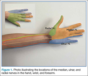
Patient Selection
Before performing a nerve block, the EP must first determine if the patient is an appropriate candidate. The EP should be cautious in performing a nerve block on any patient who has paresthesias, tingling, or weakness, as the block will complicate further examinations. Likewise, a nerve block may be contraindicated in a patient in whom compartment syndrome is a concern, since the analgesic effect will inhibit the patient’s ability to sense increasing pain or worsening paresthesias.
Equipment and Preprocedure Care
An ultrasound-guided nerve block is performed using the linear high-frequency probe. Prior to the procedure, standard infection-control measures should be taken—ie, thoroughly cleaning the preinjection site and using a transducer-probe cover. Regarding the choice of anesthetic, either bupivacaine or lidocaine is appropriate; however, bupivacaine will provide a longer duration of analgesia. To administer the anesthetic, we typically use a regular cutting needle or a spinal needle. A review of the literature typically suggests either noncutting needle tips or tips with short bevels. There is a paucity of data on needle tip selection. The use of noncutting needle tips or tips with short bevels may be a better choice than a regular cutting needle or a spinal needle because they may decrease the chance of intraneural injection and consequent nerve injury.
Single- Versus Two-Person Technique
Peripheral nerve blocks can be performed using either a single- or two-person technique. In the one-person technique, the operator manipulates both the probe and the syringe. The two-person technique, however, requires the addition of tubing between the needle and the syringe. This can be done with the addition of a small section of intravenous (IV) tubing or by connecting two pieces of tubing together (the type traditionally placed on IV catheters). The operator holds the needle and the probe while the syringe and injection are controlled by the second person. Then, with the ultrasound machine set at the nerve or soft-tissue presetting, the scan begins by placing the probe in a transverse orientation.
Nerve Location and Identification
As previously noted, the ulnar, median, and radial nerves have traditionally been identified through use of the landmark technique just proximal to the wrist. The nerves can be located initially at these sites and then traced proximally.
Ulnar Nerve
The ulnar nerve is located on the ulnar side of the forearm, just proximal to the wrist. (Figure 2a and 2b). The clinician should begin by fanning the probe at the wrist to find the ulnar artery and locate the nerve bundle. The ulnar nerve is also located on the ulnar side of the ulnar artery. The nerve will diverge from the path of the artery as it is traced proximally. To decrease the chance of an arterial injection/injury, the clinician should administer a nerve block after separating these two structures.
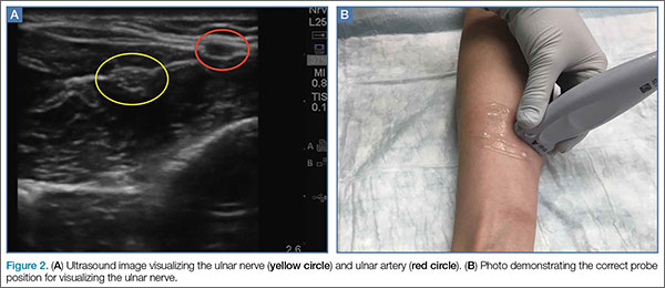
Median Nerve
The clinician can employ the landmark approach to help find the nerve; then the scan should begin at the carpal tunnel. On ultrasound, the tendons in the carpal tunnel will appear similar to nerves (ie, round and hyperechoic) compared to surrounding muscle. As one continues to slide the probe up the forearm, the tendons will become muscles and a single hyperechoic structure will remain—the median nerve running in between the flexor digitorum superificialis and the flexor digitorum profundus (Figure 3a and 3b). Since there is no artery alongside the median nerve, it can be traced proximally; therefore, the procedure can be performed in any convenient location.
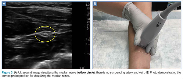
Radial Nerve
Of the three nerves, the radial nerve is the most challenging to visualize on ultrasound. There are two approaches to performing a radial nerve block. In the first approach, the radial nerve can be found just proximal to the wrist crease on the radial side of the radial artery (Figure 4a and 4b). This nerve is typically much smaller and harder to visualize at this level; it can be traced proximally and the block performed at this location. In the second approach, the radial nerve can be located 3 to 4 cm proximal to the elbow with the probe located anterolaterally (Figure 5a and 5b). In this location, the radial nerve lies between the brachialis and the brachioradialis muscles. In this approach, the nerve is much larger and easier to visualize.
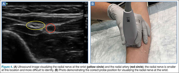
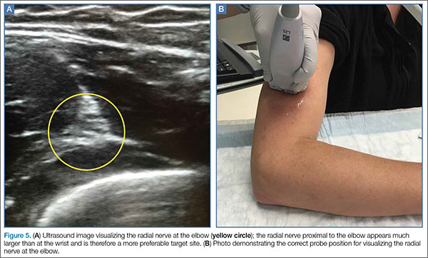
Performing the Block
Prior to performing an anesthetic block at the ulnar, median, or radial nerve at the wrist, the clinician should first place the patient in a sitting or supine position with the appropriate elbow extended. When performing the block at the radial nerve above the elbow, the hand is typically placed in a resting position on the patient’s abdomen. When localizing the nerve, the angle of the transducer can vary the appearance of the nerve dramatically. To ensure the best possible view, the clinician should slowly “rock” the probe back and forth 10° to 20° in plane with the long axis of the arm, making sure the probe is placed as perpendicular as possible to the nerve. Once the nerve is identified, the clinician can follow it up and down the forearm with the probe to identify the best site to perform the block. In the optimal location, there should be a clear path that is as superficial as possible and avoids any vascular structures. We prefer using an in-plane technique to perform the nerve block to visualize the entire needle as it approaches the nerve. Once the site has been determined, the clinician should slowly inject 4 to 5 cc of anesthetic around the nerve, with the objective to partially surround the nerve. There is no need to completely surround the nerve, as doing so is not necessary to achieve a successful block. The clinician should stop immediately if the patient reports pain or if there is increased resistance, because this could indicate an intraneural injection.
Summary
Ultrasound-guided peripheral nerve blocks are an excellent option for providing regional anesthesia to lacerations and wounds that are too large for a local anesthetic. This technique can provide better analgesic relief, enhancing patient care.
Emergency physicians (EPs) have traditionally used the landmark technique to block the radial, ulnar, and median nerves at the wrist (Figure 1). Many times, however, there is a need to perform the block more proximally. Performing these blocks with real-time ultrasound guidance allows the clinician to visually target the nerve, requires less anesthetic agent, and helps to avoid vascular structures. As with any procedure, employing the appropriate technique, along with practice, increases the success of the block.
Patient Selection
Before performing a nerve block, the EP must first determine if the patient is an appropriate candidate. The EP should be cautious in performing a nerve block on any patient who has paresthesias, tingling, or weakness, as the block will complicate further examinations. Likewise, a nerve block may be contraindicated in a patient in whom compartment syndrome is a concern, since the analgesic effect will inhibit the patient’s ability to sense increasing pain or worsening paresthesias.
Equipment and Preprocedure Care
An ultrasound-guided nerve block is performed using the linear high-frequency probe. Prior to the procedure, standard infection-control measures should be taken—ie, thoroughly cleaning the preinjection site and using a transducer-probe cover. Regarding the choice of anesthetic, either bupivacaine or lidocaine is appropriate; however, bupivacaine will provide a longer duration of analgesia. To administer the anesthetic, we typically use a regular cutting needle or a spinal needle. A review of the literature typically suggests either noncutting needle tips or tips with short bevels. There is a paucity of data on needle tip selection. The use of noncutting needle tips or tips with short bevels may be a better choice than a regular cutting needle or a spinal needle because they may decrease the chance of intraneural injection and consequent nerve injury.
Single- Versus Two-Person Technique
Peripheral nerve blocks can be performed using either a single- or two-person technique. In the one-person technique, the operator manipulates both the probe and the syringe. The two-person technique, however, requires the addition of tubing between the needle and the syringe. This can be done with the addition of a small section of intravenous (IV) tubing or by connecting two pieces of tubing together (the type traditionally placed on IV catheters). The operator holds the needle and the probe while the syringe and injection are controlled by the second person. Then, with the ultrasound machine set at the nerve or soft-tissue presetting, the scan begins by placing the probe in a transverse orientation.
Nerve Location and Identification
As previously noted, the ulnar, median, and radial nerves have traditionally been identified through use of the landmark technique just proximal to the wrist. The nerves can be located initially at these sites and then traced proximally.
Ulnar Nerve
The ulnar nerve is located on the ulnar side of the forearm, just proximal to the wrist. (Figure 2a and 2b). The clinician should begin by fanning the probe at the wrist to find the ulnar artery and locate the nerve bundle. The ulnar nerve is also located on the ulnar side of the ulnar artery. The nerve will diverge from the path of the artery as it is traced proximally. To decrease the chance of an arterial injection/injury, the clinician should administer a nerve block after separating these two structures.
Median Nerve
The clinician can employ the landmark approach to help find the nerve; then the scan should begin at the carpal tunnel. On ultrasound, the tendons in the carpal tunnel will appear similar to nerves (ie, round and hyperechoic) compared to surrounding muscle. As one continues to slide the probe up the forearm, the tendons will become muscles and a single hyperechoic structure will remain—the median nerve running in between the flexor digitorum superificialis and the flexor digitorum profundus (Figure 3a and 3b). Since there is no artery alongside the median nerve, it can be traced proximally; therefore, the procedure can be performed in any convenient location.
Radial Nerve
Of the three nerves, the radial nerve is the most challenging to visualize on ultrasound. There are two approaches to performing a radial nerve block. In the first approach, the radial nerve can be found just proximal to the wrist crease on the radial side of the radial artery (Figure 4a and 4b). This nerve is typically much smaller and harder to visualize at this level; it can be traced proximally and the block performed at this location. In the second approach, the radial nerve can be located 3 to 4 cm proximal to the elbow with the probe located anterolaterally (Figure 5a and 5b). In this location, the radial nerve lies between the brachialis and the brachioradialis muscles. In this approach, the nerve is much larger and easier to visualize.
Performing the Block
Prior to performing an anesthetic block at the ulnar, median, or radial nerve at the wrist, the clinician should first place the patient in a sitting or supine position with the appropriate elbow extended. When performing the block at the radial nerve above the elbow, the hand is typically placed in a resting position on the patient’s abdomen. When localizing the nerve, the angle of the transducer can vary the appearance of the nerve dramatically. To ensure the best possible view, the clinician should slowly “rock” the probe back and forth 10° to 20° in plane with the long axis of the arm, making sure the probe is placed as perpendicular as possible to the nerve. Once the nerve is identified, the clinician can follow it up and down the forearm with the probe to identify the best site to perform the block. In the optimal location, there should be a clear path that is as superficial as possible and avoids any vascular structures. We prefer using an in-plane technique to perform the nerve block to visualize the entire needle as it approaches the nerve. Once the site has been determined, the clinician should slowly inject 4 to 5 cc of anesthetic around the nerve, with the objective to partially surround the nerve. There is no need to completely surround the nerve, as doing so is not necessary to achieve a successful block. The clinician should stop immediately if the patient reports pain or if there is increased resistance, because this could indicate an intraneural injection.
Summary
Ultrasound-guided peripheral nerve blocks are an excellent option for providing regional anesthesia to lacerations and wounds that are too large for a local anesthetic. This technique can provide better analgesic relief, enhancing patient care.
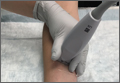
Does Optic Nerve Sheath Diameter Ultrasonography Permit Accurate Detection of Real-Time Changes in ICP?
Case Scenarios
Case 1
While working abroad in a resource-limited environment, a patient was brought in after falling and hitting his head. Initially, the patient was awake and alert, but he gradually became minimally responsive, with a Glasgow Coma Scale score of 9. Your facility did not have computed tomography (CT) or magnetic resonance imaging (MRI), but did have a point-of-care ultrasound (US) machine. You measured the patient’s optic nerve sheath diameter (ONSD) with the US and found a diameter of 4.5 mm in each eye. With this clinical change, you wondered if repeat US scans to detect increasing intracranial pressure (ICP) would represent changes in the patient’s condition.
Case 2
A patient who presented with an intracranial hemorrhage was treated with hypertonic saline and was awaiting neurosurgical placement of an extraventicular drain. During this time, a resident who was on a US rotation asked you if she would be able to detect changes in the patient’s ICP using US rather than placing an invasive device. How do you respond?
In adults, ICP is normally 10 to 15 mm Hg. It may be pathologically increased in several life-threatening conditions, including traumatic brain injury (TBI), subarachnoid hemorrhage, central venous thrombosis, brain tumor, and abscess. It is also increased by nonacute pathology, such as idiopathic intracranial hypertension (IIH), which also is known as pseudotumor cerebri. In patients with acute pathology, ICP above 20 mm Hg is generally considered an indication for treatment.1 Indications for ICP monitoring in TBI include positive CT findings, patient age greater than 40 years, systemic hypotension, or abnormal flexion/extension in response to pain.2 Other reasons to monitor ICP include the management of pseudotumor cerebri or after ventriculoperitoneal shunt surgery.3
Unfortunately, current methods of ICP monitoring have significant drawbacks and limitations. The gold standard of ICP monitoring—measurement using an intraventricular catheter—increases the risks of infection and hemorrhage, requires the skill of a neurosurgeon, and may be contraindicated due to coagulopathy or thrombocytopenia. It also cannot be done in a prehospital setting and only to a limited extent in the ED.4
Computed tomography scans and MRI can assess elevated ICP, but these tests are expensive, may increase patient radiation exposure, require patient transport, and may not always detect raised ICP. In the appropriate clinical context, signs present on physical examination, such as decorticate/decerebrate posturing, papilledema, or fixed/dilated pupils, may be highly suggestive of an increased ICP, but sensitivity and specificity are inadequate. Delay in diagnosis is also a drawback of imaging and physical examination, as findings may not present until ICP has been persistently elevated.
Given the disadvantages of current means of assessing elevated ICP, several noninvasive methods of measuring ICP are being investigated. These include such techniques as transcranial Doppler, electroencephalogram, pupillometry, and ONSD measurements.5 This article reviews current applications of ultrasonography measurements of the ONSD in assessing elevations in ICP.
ONSD US
Assessment of ICP via measurement of the ONSD has attracted increasing attention, particularly in emergency medicine. Measurements of the ONSD are possible with CT, MRI, and US. Of these modalities, ONSD US has attracted the most interest, due to its low cost, wide availability, and rapidity. It does not require patient transport, and does not expose a patient to additional radiation. In addition, ONSD US has been utilized in low-resource settings, and may be particularly useful in prehospital and mass-casualty situations.6
The underlying relationship between ONSD and ICP is a result of the enclosure of the subarachnoid space by the ONS. Increased ICP leads to expansion of the ONS, particularly at 3 mm behind the globe, in the retrobulbar compartment (Figures 1 and 2).7
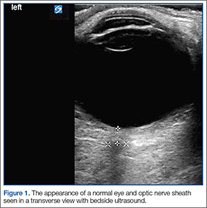
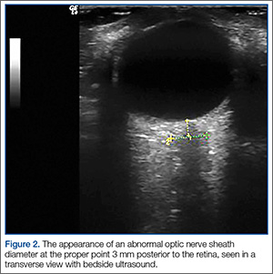
Unfortunately, it is not possible to precisely determine ICP from an ONSD measurement, because baseline ONSD values and elasticity vary significantly within the population.4,8 As a result, ONSD US has been investigated mostly for its ability to detect qualitative changes—particularly as a screen for elevated ICP. Optic nerve sheath diameter has high discriminative value in its ability to distinguish normal from elevated ICP. In a meta-analysis, Dubourg et al9 showed that the technique had an area under the summary receiver-operating curve of 0.94, signifying excellent test accuracy to diagnose elevated ICPs.
Researchers have attempted to determine a threshold value of ONSD that would serve as a clinically useful predictor of elevated ICP. Currently, this value ranges from 4.8 to 5.9 mm, depending on the study9; 5 mm is commonly used clinically as a threshold.10
Using ONSD US to Monitor Rapid Changes in ICP
While the use of the ONSD technique to screen for elevated ICP is relatively well established, the use of ONSD US to track acute changes in ICP is not as well studied. Serial tracking of acute changes could be useful in a patient at risk for intracranial hypertension secondary to trauma, to monitor the results of treating a patient with IIH, or after ventriculoperitoneal shunt placement.3
In Vivo Data
In 1993, Tamburrelli et al11 performed the first ONSD intrathecal infusion study, using A-scan sonography, and concluded that there was a “direct, biphasic, positive relation between diastolic intracranial pressure and optic nerve diameters” and that the data showed “rapid changes of optic nerve diameters in response to variation of intracranial pressure.”
In 1997, Hansen and Helmke12 recorded ONSD versus ICP data in the first intrathecal infusion test to use B-scan mode sonography. Ultrasonography was performed at 2- to 4-minute intervals. Their data demonstrated a linear relationship between ICP and ONSD over a particular cerebrospinal fluid pressure interval. They noted that “this interval differed between patients: ONS dilation commenced at pressure thresholds between 15 mm Hg and 30 mm Hg and in some patients saturation of the response (constant ONSD) occurred between 30 mm Hg and 40 mm Hg.”
The slope of ONSD versus ICP curve varied considerably by patient, making it impossible to infer an absolute ICP value from an ONSD without prior knowledge of the patient’s ratio. Similar to the data from Tamburrelli et al,11 Hansen and Helmke12 also found that there was no lag in ONSD response to ICP: “Within this interval, no temporal delay of the ONS response was noted.”
The only study comparing real-time ONSD data to gold-standard measurements of rapidly changing ICP in humans was performed by Maissan et al13 in 2015. This study involved a cohort of 18 patients who had suffered TBI and had intraparenchymal probes inserted. Because ICP rises transiently during endotracheal tube suctioning due to irritation of the trachea, the increase and subsequent decrease after suctioning was an ideal time to perform ONSD measurements and compare them to simultaneous gold-standard ICP measurements. The ONSD US measurements were performed 30 to 60 seconds prior to suctioning, during suctioning, and 30 to 60 seconds after suctioning.
Even during this very rapid time course, a strong correlation between ICP and ONSD measurements was demonstrated. The R2 value was 0.80. There was no perceptible “lag” in ONSD change; changes in ICP were immediately reflected in ONSD. Notably, an absolute change of less than 8 to 10 mm Hg in ICP did not affect ONSD, which is consistent with data collected by Hansen and Helmke.12
Therapeutic Lumbar Puncture for IIH
There are two case reports of ONSD US measurements being taken pre- and postlumbar puncture (LP) in patients with IIH. In the first, in 1989 Galetta et al14 used A-scan US to measure pre- and post-LP ONSD in a woman with papilledema secondary to IIH. They found a significant reduction in ONSD bilaterally “within minutes” of performing the LP.14
The second case report was published in 2015 by Singleton et al.15 They recorded ONSD measurements 30 minutes pre- and post-LP in a woman who presented to the ED with symptoms from elevated ICP. After reduction of pressure via LP, they recorded a significant reduction in ONSD bilaterally.15
Cadaver Data
Hansen et al16 evaluated the distensibility and elasticity of the ONS using postmortem optic nerve preparations. The ONSD was recorded 200 seconds after each pressure increase, which was long enough to achieve stable diameters. They found a linear correlation between pressure increases of 5 to 45 mm Hg and ONSD. This would suggest a potential positively correlated change in ONSD with in vivo changes in ICP. However, this still needs further clinical study to better assess measurable changes in living patients.
Conclusion
Published data have consistently demonstrated that changes in ICP are rapidly transmitted to the optic nerve sheath and that there does not appear to be a temporal lag in the ONSD. Based on in vivo data, the relationship between ICP and ONSD appears to be linear only over a range of moderately elevated ICP. According to Hansen and Helmke,12 this range starts at approximately 18 to 30 mm Hg, and ends at approximately 40 to 45 mm Hg. Maissan et al13 observed similar findings: “At low levels, ICP changes (8-10 mm Hg) do not affect the ONSD.”
There is still need for additional research to validate and refine these findings. Only one study has compared gold-standard ICP measurements with ONSD US measurements in real time,13 and the literature on ONSD US in tracking ICP after therapeutic LP in IIH consists of only two case reports.
Thus, with some caveats, ONSD US appears to permit qualitative tracking of ICP in real time. This supports its use in situations where a patient may have rapidly changing ICP, such as close monitoring of patients at risk for elevated ICP in a critical care setting, and response to treatment in patients with IIH.
1. Stocchetti N, Maas AI. Traumatic intracranial hypertension. N Engl J Med. 2014;370(22):2121-2130.
2. Brain Trauma Foundation; American Association of Neurological Surgeons; Congress of Neurological Surgeons; et al. Guidelines for the management of severe traumatic brain injury. VI. Indications for intracranial pressure monitoring. J Neurotrauma. 2007;24(Suppl 1):S37-S44.
3. Choi SH, Min KT, Park EK, Kim MS, Jung JH, Kim H. Ultrasonography of the optic nerve sheath to assess intracranial pressure changes after ventriculo-peritoneal shunt surgery in children with hydrocephalus: a prospective observational study. Anaesthesia. 2015;70(11):1268-1273.
4. Kristiansson H, Nissborg E, Bartek J Jr, Andresen M, Reinstrup P, Romner B. Measuring elevated intracranial pressure through noninvasive methods: a review of the literature. J Neurosurg Anesthesiol. 2013;25(4):372-385.
5. Rajajee V, Thyagarajan P, Rajagopalan RE. Optic nerve ultrasonography for detection of raised intracranial pressure when invasive monitoring is unavailable. Neurol India. 2010;58(5):812-813.
6. Robba C, Baciqaluppi S, Cardim D, Donnelly J, Bertuccio A, Czosnyka M. Non-invasive assessment of intracranial pressure. Acta Neurol Scand. 2016;134(1):4-21.
7. Hansen HC, Helmke K. The subarachnoid space surrounding the optic nerves. An ultrasound study of the optic nerve sheath. Surg Radiol Anat. 1996;18(4):323-328.
8. Hansen HC, Lagrèze W, Krueger O, Helmke K. Dependence of the optic nerve sheath diameter on acutely applied subarachnoidal pressure - an experimental ultrasound study. Acta Ophthalmol. 2011;89(6):e528-e532.
9. Dubourg J, Javouhey E, Geeraerts T, Messerer M, Kassai B. Ultrasonography of optic nerve sheath diameter for detection of raised intracranial pressure: a systematic review and meta-analysis. Intensive Care Med. 2011;37(7):1059-1068.
10. Kimberly HH, Shah S, Marill K, Noble V. Correlation of optic nerve sheath diameter with direct measurement of intracranial pressure. Acad Emerg Med. 2008;15(2):201-204.
11. Tamburrelli C, Anile C, Mangiola A, Falsini B, Palma P. CSF dynamic parameters and changes of optic nerve diameters measured by standardized echography. In: Till P, ed. Ophthalmic Echography 13: Proceedings of the 13th SIDUO Congress, Vienna, Austria, 1990; vol 55. Dordrecht, Netherlands: Springer Netherlands; 1993:101-109.
12. Hansen HC, Helmke K. Validation of the optic nerve sheath response to changing cerebrospinal fluid pressure: ultrasound findings during intrathecal infusion tests. J Neurosurg. 1997;87(1):34-40.
13. Maissan IM, Dirven PJ, Haitsma IK, Hoeks SE, Gommers D, Stolker RJ. Ultrasonographic measured optic nerve sheath diameter as an accurate and quick monitor for changes in intracranial pressure. J Neurosurg. 2015;123(3)743-747.
14. Galetta S, Byrne SF, Smith JL. Echographic correlation of optic nerve sheath size and cerebrospinal fluid pressure. J Clin Neuroophthalmol. 1989;9(2):79-82.
15. Singleton J, Dagan A, Edlow JA, Hoffmann B. Real-time optic nerve sheath diameter reduction measured with bedside ultrasound after therapeutic lumbar puncture in a patient with idiopathic intracranial hypertension. Am J Emerg Med. 2015;33(6):860.e5-e7.
16. Hansen HC, Lagrèze W, Krueger O, Helmke K. Dependence of the optic nerve sheath diameter on acutely applied subarachnoidal pressure—an experimental ultrasound study. Acta Ophthalmol. 2011;89(6):e528-e532.
Case Scenarios
Case 1
While working abroad in a resource-limited environment, a patient was brought in after falling and hitting his head. Initially, the patient was awake and alert, but he gradually became minimally responsive, with a Glasgow Coma Scale score of 9. Your facility did not have computed tomography (CT) or magnetic resonance imaging (MRI), but did have a point-of-care ultrasound (US) machine. You measured the patient’s optic nerve sheath diameter (ONSD) with the US and found a diameter of 4.5 mm in each eye. With this clinical change, you wondered if repeat US scans to detect increasing intracranial pressure (ICP) would represent changes in the patient’s condition.
Case 2
A patient who presented with an intracranial hemorrhage was treated with hypertonic saline and was awaiting neurosurgical placement of an extraventicular drain. During this time, a resident who was on a US rotation asked you if she would be able to detect changes in the patient’s ICP using US rather than placing an invasive device. How do you respond?
In adults, ICP is normally 10 to 15 mm Hg. It may be pathologically increased in several life-threatening conditions, including traumatic brain injury (TBI), subarachnoid hemorrhage, central venous thrombosis, brain tumor, and abscess. It is also increased by nonacute pathology, such as idiopathic intracranial hypertension (IIH), which also is known as pseudotumor cerebri. In patients with acute pathology, ICP above 20 mm Hg is generally considered an indication for treatment.1 Indications for ICP monitoring in TBI include positive CT findings, patient age greater than 40 years, systemic hypotension, or abnormal flexion/extension in response to pain.2 Other reasons to monitor ICP include the management of pseudotumor cerebri or after ventriculoperitoneal shunt surgery.3
Unfortunately, current methods of ICP monitoring have significant drawbacks and limitations. The gold standard of ICP monitoring—measurement using an intraventricular catheter—increases the risks of infection and hemorrhage, requires the skill of a neurosurgeon, and may be contraindicated due to coagulopathy or thrombocytopenia. It also cannot be done in a prehospital setting and only to a limited extent in the ED.4
Computed tomography scans and MRI can assess elevated ICP, but these tests are expensive, may increase patient radiation exposure, require patient transport, and may not always detect raised ICP. In the appropriate clinical context, signs present on physical examination, such as decorticate/decerebrate posturing, papilledema, or fixed/dilated pupils, may be highly suggestive of an increased ICP, but sensitivity and specificity are inadequate. Delay in diagnosis is also a drawback of imaging and physical examination, as findings may not present until ICP has been persistently elevated.
Given the disadvantages of current means of assessing elevated ICP, several noninvasive methods of measuring ICP are being investigated. These include such techniques as transcranial Doppler, electroencephalogram, pupillometry, and ONSD measurements.5 This article reviews current applications of ultrasonography measurements of the ONSD in assessing elevations in ICP.
ONSD US
Assessment of ICP via measurement of the ONSD has attracted increasing attention, particularly in emergency medicine. Measurements of the ONSD are possible with CT, MRI, and US. Of these modalities, ONSD US has attracted the most interest, due to its low cost, wide availability, and rapidity. It does not require patient transport, and does not expose a patient to additional radiation. In addition, ONSD US has been utilized in low-resource settings, and may be particularly useful in prehospital and mass-casualty situations.6
The underlying relationship between ONSD and ICP is a result of the enclosure of the subarachnoid space by the ONS. Increased ICP leads to expansion of the ONS, particularly at 3 mm behind the globe, in the retrobulbar compartment (Figures 1 and 2).7
Unfortunately, it is not possible to precisely determine ICP from an ONSD measurement, because baseline ONSD values and elasticity vary significantly within the population.4,8 As a result, ONSD US has been investigated mostly for its ability to detect qualitative changes—particularly as a screen for elevated ICP. Optic nerve sheath diameter has high discriminative value in its ability to distinguish normal from elevated ICP. In a meta-analysis, Dubourg et al9 showed that the technique had an area under the summary receiver-operating curve of 0.94, signifying excellent test accuracy to diagnose elevated ICPs.
Researchers have attempted to determine a threshold value of ONSD that would serve as a clinically useful predictor of elevated ICP. Currently, this value ranges from 4.8 to 5.9 mm, depending on the study9; 5 mm is commonly used clinically as a threshold.10
Using ONSD US to Monitor Rapid Changes in ICP
While the use of the ONSD technique to screen for elevated ICP is relatively well established, the use of ONSD US to track acute changes in ICP is not as well studied. Serial tracking of acute changes could be useful in a patient at risk for intracranial hypertension secondary to trauma, to monitor the results of treating a patient with IIH, or after ventriculoperitoneal shunt placement.3
In Vivo Data
In 1993, Tamburrelli et al11 performed the first ONSD intrathecal infusion study, using A-scan sonography, and concluded that there was a “direct, biphasic, positive relation between diastolic intracranial pressure and optic nerve diameters” and that the data showed “rapid changes of optic nerve diameters in response to variation of intracranial pressure.”
In 1997, Hansen and Helmke12 recorded ONSD versus ICP data in the first intrathecal infusion test to use B-scan mode sonography. Ultrasonography was performed at 2- to 4-minute intervals. Their data demonstrated a linear relationship between ICP and ONSD over a particular cerebrospinal fluid pressure interval. They noted that “this interval differed between patients: ONS dilation commenced at pressure thresholds between 15 mm Hg and 30 mm Hg and in some patients saturation of the response (constant ONSD) occurred between 30 mm Hg and 40 mm Hg.”
The slope of ONSD versus ICP curve varied considerably by patient, making it impossible to infer an absolute ICP value from an ONSD without prior knowledge of the patient’s ratio. Similar to the data from Tamburrelli et al,11 Hansen and Helmke12 also found that there was no lag in ONSD response to ICP: “Within this interval, no temporal delay of the ONS response was noted.”
The only study comparing real-time ONSD data to gold-standard measurements of rapidly changing ICP in humans was performed by Maissan et al13 in 2015. This study involved a cohort of 18 patients who had suffered TBI and had intraparenchymal probes inserted. Because ICP rises transiently during endotracheal tube suctioning due to irritation of the trachea, the increase and subsequent decrease after suctioning was an ideal time to perform ONSD measurements and compare them to simultaneous gold-standard ICP measurements. The ONSD US measurements were performed 30 to 60 seconds prior to suctioning, during suctioning, and 30 to 60 seconds after suctioning.
Even during this very rapid time course, a strong correlation between ICP and ONSD measurements was demonstrated. The R2 value was 0.80. There was no perceptible “lag” in ONSD change; changes in ICP were immediately reflected in ONSD. Notably, an absolute change of less than 8 to 10 mm Hg in ICP did not affect ONSD, which is consistent with data collected by Hansen and Helmke.12
Therapeutic Lumbar Puncture for IIH
There are two case reports of ONSD US measurements being taken pre- and postlumbar puncture (LP) in patients with IIH. In the first, in 1989 Galetta et al14 used A-scan US to measure pre- and post-LP ONSD in a woman with papilledema secondary to IIH. They found a significant reduction in ONSD bilaterally “within minutes” of performing the LP.14
The second case report was published in 2015 by Singleton et al.15 They recorded ONSD measurements 30 minutes pre- and post-LP in a woman who presented to the ED with symptoms from elevated ICP. After reduction of pressure via LP, they recorded a significant reduction in ONSD bilaterally.15
Cadaver Data
Hansen et al16 evaluated the distensibility and elasticity of the ONS using postmortem optic nerve preparations. The ONSD was recorded 200 seconds after each pressure increase, which was long enough to achieve stable diameters. They found a linear correlation between pressure increases of 5 to 45 mm Hg and ONSD. This would suggest a potential positively correlated change in ONSD with in vivo changes in ICP. However, this still needs further clinical study to better assess measurable changes in living patients.
Conclusion
Published data have consistently demonstrated that changes in ICP are rapidly transmitted to the optic nerve sheath and that there does not appear to be a temporal lag in the ONSD. Based on in vivo data, the relationship between ICP and ONSD appears to be linear only over a range of moderately elevated ICP. According to Hansen and Helmke,12 this range starts at approximately 18 to 30 mm Hg, and ends at approximately 40 to 45 mm Hg. Maissan et al13 observed similar findings: “At low levels, ICP changes (8-10 mm Hg) do not affect the ONSD.”
There is still need for additional research to validate and refine these findings. Only one study has compared gold-standard ICP measurements with ONSD US measurements in real time,13 and the literature on ONSD US in tracking ICP after therapeutic LP in IIH consists of only two case reports.
Thus, with some caveats, ONSD US appears to permit qualitative tracking of ICP in real time. This supports its use in situations where a patient may have rapidly changing ICP, such as close monitoring of patients at risk for elevated ICP in a critical care setting, and response to treatment in patients with IIH.
1. Stocchetti N, Maas AI. Traumatic intracranial hypertension. N Engl J Med. 2014;370(22):2121-2130.
2. Brain Trauma Foundation; American Association of Neurological Surgeons; Congress of Neurological Surgeons; et al. Guidelines for the management of severe traumatic brain injury. VI. Indications for intracranial pressure monitoring. J Neurotrauma. 2007;24(Suppl 1):S37-S44.
3. Choi SH, Min KT, Park EK, Kim MS, Jung JH, Kim H. Ultrasonography of the optic nerve sheath to assess intracranial pressure changes after ventriculo-peritoneal shunt surgery in children with hydrocephalus: a prospective observational study. Anaesthesia. 2015;70(11):1268-1273.
4. Kristiansson H, Nissborg E, Bartek J Jr, Andresen M, Reinstrup P, Romner B. Measuring elevated intracranial pressure through noninvasive methods: a review of the literature. J Neurosurg Anesthesiol. 2013;25(4):372-385.
5. Rajajee V, Thyagarajan P, Rajagopalan RE. Optic nerve ultrasonography for detection of raised intracranial pressure when invasive monitoring is unavailable. Neurol India. 2010;58(5):812-813.
6. Robba C, Baciqaluppi S, Cardim D, Donnelly J, Bertuccio A, Czosnyka M. Non-invasive assessment of intracranial pressure. Acta Neurol Scand. 2016;134(1):4-21.
7. Hansen HC, Helmke K. The subarachnoid space surrounding the optic nerves. An ultrasound study of the optic nerve sheath. Surg Radiol Anat. 1996;18(4):323-328.
8. Hansen HC, Lagrèze W, Krueger O, Helmke K. Dependence of the optic nerve sheath diameter on acutely applied subarachnoidal pressure - an experimental ultrasound study. Acta Ophthalmol. 2011;89(6):e528-e532.
9. Dubourg J, Javouhey E, Geeraerts T, Messerer M, Kassai B. Ultrasonography of optic nerve sheath diameter for detection of raised intracranial pressure: a systematic review and meta-analysis. Intensive Care Med. 2011;37(7):1059-1068.
10. Kimberly HH, Shah S, Marill K, Noble V. Correlation of optic nerve sheath diameter with direct measurement of intracranial pressure. Acad Emerg Med. 2008;15(2):201-204.
11. Tamburrelli C, Anile C, Mangiola A, Falsini B, Palma P. CSF dynamic parameters and changes of optic nerve diameters measured by standardized echography. In: Till P, ed. Ophthalmic Echography 13: Proceedings of the 13th SIDUO Congress, Vienna, Austria, 1990; vol 55. Dordrecht, Netherlands: Springer Netherlands; 1993:101-109.
12. Hansen HC, Helmke K. Validation of the optic nerve sheath response to changing cerebrospinal fluid pressure: ultrasound findings during intrathecal infusion tests. J Neurosurg. 1997;87(1):34-40.
13. Maissan IM, Dirven PJ, Haitsma IK, Hoeks SE, Gommers D, Stolker RJ. Ultrasonographic measured optic nerve sheath diameter as an accurate and quick monitor for changes in intracranial pressure. J Neurosurg. 2015;123(3)743-747.
14. Galetta S, Byrne SF, Smith JL. Echographic correlation of optic nerve sheath size and cerebrospinal fluid pressure. J Clin Neuroophthalmol. 1989;9(2):79-82.
15. Singleton J, Dagan A, Edlow JA, Hoffmann B. Real-time optic nerve sheath diameter reduction measured with bedside ultrasound after therapeutic lumbar puncture in a patient with idiopathic intracranial hypertension. Am J Emerg Med. 2015;33(6):860.e5-e7.
16. Hansen HC, Lagrèze W, Krueger O, Helmke K. Dependence of the optic nerve sheath diameter on acutely applied subarachnoidal pressure—an experimental ultrasound study. Acta Ophthalmol. 2011;89(6):e528-e532.
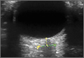
Ovarian hyperstimulation syndrome as a complication of molar pregnancy
An 18-year-old woman, pregnant for the third time, presented to the emergency department with constant vaginal bleeding and intermittent cramping for the past 3 weeks. Her last menstrual period was 14 weeks and 2 days ago. In her previous two pregnancies, she had given birth to one living child and had had one miscarriage.
Physical examination suggested that her uterus was bigger than expected for the gestational age, measuring 23 cm from the symphysis pubis to the uterine fundus. Ultrasonography in the obstetrics service revealed a “snowstorm” appearance strongly suggestive of molar pregnancy. Her level of beta human chorionic gonadotropin (beta-hCG) was greater than 1,125,000 mIU/mL (reference range for 14 weeks of pregnancy 18,300–137,000). Dilation and curettage was performed, and pathologic study confirmed molar pregnancy.
On the 6th day after the procedure, she returned to the emergency department with progressive abdominal pain, distention, and nausea. Her blood urea nitrogen level was 8 mg/dL (reference range 5–20 mg/dL) and her serum creatinine level was 0.5 mg/dL (0.5–0.9). Computed tomography of the abdomen and pelvis demonstrated an enlarged and bulky uterus with heterogeneous enhancement. The ovaries were greatly enlarged with multiple cysts, and massive ascites was noted in the abdomen (Figures 1 and 2). These findings confirmed the diagnosis of ovarian hyperstimulation syndrome (OHSS).
OVARIAN HYPERSTIMULATION SYNDROME
OHSS is enlargement of the ovaries associated with fluid shifts secondary to ovulation induction therapy with clomiphene citrate or hCG.1 In its mild form, it is a common complication, seen in 5% to 10% of patients undergoing ovulation induction; the moderate form is reported in 2% to 4% of patients undergoing ovulation induction, and the severe form in 0.1% to 0.5%.2 It may also occur spontaneously after pregnancy or with any condition that leads to a rise in hCG levels.
Factors associated with a high risk of developing OHSS include young age, low body weight, polycystic ovary syndrome, a high serum estradiol level, and a history of OHSS.3,4
In our patient, OHSS was secondary to molar pregnancy and markedly elevated hCG levels. Hydatidiform mole or molar pregnancy is a cystic swelling of the chorionic villi and proliferation of the trophoblastic epithelium. Elevated circulating hCG is thought to lead to ovarian enlargement and multiple cysts; this stimulates the ovaries to secrete vasoactive substances, increasing vascular permeability, leading to fluid shifts and the accumulation of extravascular fluid, resulting in renal failure, hypovolemic shock, ascites, and pleural and pericardial effusions.5 This acute shift produces hypovolemia, which may result in multiple organ failure, hemoconcentration (hematocrit > 45%), thrombosis, and disseminated intravascular coagulation from the increased viscosity of the blood.
GRADING OF OHSS IS BASED ON SYMPTOMS, TEST RESULTS, IMAGING
The severity of OHSS is classified as mild, moderate, or severe, with further grading as follows5,6:
Mild OHSS
- Grade 1: abdominal distention and discomfort.
- Grade 2: features of grade 1, plus nausea and vomiting, with or without diarrhea, and ovarian size of 5 to 12 cm.
Moderate OHSS
- Grade 3: mild OHSS with imaging evidence of ascites.
Severe OHSS
- Grade 4: moderate OHSS plus clinical evidence of ascites, with or without hydrothorax.
- Grade 5: all of the above plus hypovolemia, hemoconcentration (hematocrit > 45%), coagulation abnormalities, and oliguria.
- Grade 6: all the features of grades 1 to 4 plus hypovolemia, hemoconcentration (hematocrit > 55%), anuria, renal failure, venous thrombosis, and adult respiratory distress syndrome. This can be life-threatening and may require hospitalization.
TREATMENT
Treatment is generally conservative and includes management of ascites and pleural effusion and supportive care.
Mild OHSS can be treated on an outpatient basis with bed rest, oral analgesics, limited oral intake, and avoidance of vaginal intercourse, and usually resolves in 10 to 14 days. Moderate and severe OHSS require bed rest and aggressive fluid resuscitation. OHSS in patients with renal failure, relentless hemoconcentration, or thrombovascular accident can be life-threatening and may require intensive-care monitoring.
Paracentesis may be performed if tension ascites and oliguria or anuria develop.2 Prophylactic anticoagulation with warfarin, heparin, or low-molecular-weight heparin is indicated in women with a high tendency for thrombotic events who develop moderate to severe OHSS.3,4
Surgical intervention may be necessary in patients with ectopic pregnancy, ovarian torsion, or ruptured ovarian cyst.
Our patient was treated conservatively with supportive care and experienced a full recovery.
- Arora R, Merhi ZO, Khulpateea N, Roth D, Minkoff H. Ovarian hyperstimulation syndrome after a molar pregnancy evacuation. Fertil Steril 2008; 90:1197.e5–e7.
- Fiedler K, Ezcurra D. Predicting and preventing ovarian hyperstimulation syndrome (OHSS): the need for individualized not standardized treatment. Reprod Biol Endocrinol 2012; 10:32.
- Mor YS, Schenker JG. Ovarian hyperstimulation syndrome and thrombotic events. Am J Reprod Immunol 2014; 72:541–548.
- Practice Committee of American Society for Reproductive Medicine. Ovarian hyperstimulation syndrome. Fertil Steril 2008; 90(suppl):S188–S193.
- Whelan JG 3rd, Vlahos NF. The ovarian hyperstimulation syndrome. Fertil Steril 2000; 73:883–896.
- Golan A, Weissman A. Symposium: update on prediction and management of OHSS. A modern classification of OHSS. Reprod Biomed Online 2009; 19:28–32.
An 18-year-old woman, pregnant for the third time, presented to the emergency department with constant vaginal bleeding and intermittent cramping for the past 3 weeks. Her last menstrual period was 14 weeks and 2 days ago. In her previous two pregnancies, she had given birth to one living child and had had one miscarriage.
Physical examination suggested that her uterus was bigger than expected for the gestational age, measuring 23 cm from the symphysis pubis to the uterine fundus. Ultrasonography in the obstetrics service revealed a “snowstorm” appearance strongly suggestive of molar pregnancy. Her level of beta human chorionic gonadotropin (beta-hCG) was greater than 1,125,000 mIU/mL (reference range for 14 weeks of pregnancy 18,300–137,000). Dilation and curettage was performed, and pathologic study confirmed molar pregnancy.
On the 6th day after the procedure, she returned to the emergency department with progressive abdominal pain, distention, and nausea. Her blood urea nitrogen level was 8 mg/dL (reference range 5–20 mg/dL) and her serum creatinine level was 0.5 mg/dL (0.5–0.9). Computed tomography of the abdomen and pelvis demonstrated an enlarged and bulky uterus with heterogeneous enhancement. The ovaries were greatly enlarged with multiple cysts, and massive ascites was noted in the abdomen (Figures 1 and 2). These findings confirmed the diagnosis of ovarian hyperstimulation syndrome (OHSS).
OVARIAN HYPERSTIMULATION SYNDROME
OHSS is enlargement of the ovaries associated with fluid shifts secondary to ovulation induction therapy with clomiphene citrate or hCG.1 In its mild form, it is a common complication, seen in 5% to 10% of patients undergoing ovulation induction; the moderate form is reported in 2% to 4% of patients undergoing ovulation induction, and the severe form in 0.1% to 0.5%.2 It may also occur spontaneously after pregnancy or with any condition that leads to a rise in hCG levels.
Factors associated with a high risk of developing OHSS include young age, low body weight, polycystic ovary syndrome, a high serum estradiol level, and a history of OHSS.3,4
In our patient, OHSS was secondary to molar pregnancy and markedly elevated hCG levels. Hydatidiform mole or molar pregnancy is a cystic swelling of the chorionic villi and proliferation of the trophoblastic epithelium. Elevated circulating hCG is thought to lead to ovarian enlargement and multiple cysts; this stimulates the ovaries to secrete vasoactive substances, increasing vascular permeability, leading to fluid shifts and the accumulation of extravascular fluid, resulting in renal failure, hypovolemic shock, ascites, and pleural and pericardial effusions.5 This acute shift produces hypovolemia, which may result in multiple organ failure, hemoconcentration (hematocrit > 45%), thrombosis, and disseminated intravascular coagulation from the increased viscosity of the blood.
GRADING OF OHSS IS BASED ON SYMPTOMS, TEST RESULTS, IMAGING
The severity of OHSS is classified as mild, moderate, or severe, with further grading as follows5,6:
Mild OHSS
- Grade 1: abdominal distention and discomfort.
- Grade 2: features of grade 1, plus nausea and vomiting, with or without diarrhea, and ovarian size of 5 to 12 cm.
Moderate OHSS
- Grade 3: mild OHSS with imaging evidence of ascites.
Severe OHSS
- Grade 4: moderate OHSS plus clinical evidence of ascites, with or without hydrothorax.
- Grade 5: all of the above plus hypovolemia, hemoconcentration (hematocrit > 45%), coagulation abnormalities, and oliguria.
- Grade 6: all the features of grades 1 to 4 plus hypovolemia, hemoconcentration (hematocrit > 55%), anuria, renal failure, venous thrombosis, and adult respiratory distress syndrome. This can be life-threatening and may require hospitalization.
TREATMENT
Treatment is generally conservative and includes management of ascites and pleural effusion and supportive care.
Mild OHSS can be treated on an outpatient basis with bed rest, oral analgesics, limited oral intake, and avoidance of vaginal intercourse, and usually resolves in 10 to 14 days. Moderate and severe OHSS require bed rest and aggressive fluid resuscitation. OHSS in patients with renal failure, relentless hemoconcentration, or thrombovascular accident can be life-threatening and may require intensive-care monitoring.
Paracentesis may be performed if tension ascites and oliguria or anuria develop.2 Prophylactic anticoagulation with warfarin, heparin, or low-molecular-weight heparin is indicated in women with a high tendency for thrombotic events who develop moderate to severe OHSS.3,4
Surgical intervention may be necessary in patients with ectopic pregnancy, ovarian torsion, or ruptured ovarian cyst.
Our patient was treated conservatively with supportive care and experienced a full recovery.
- Arora R, Merhi ZO, Khulpateea N, Roth D, Minkoff H. Ovarian hyperstimulation syndrome after a molar pregnancy evacuation. Fertil Steril 2008; 90:1197.e5–e7.
- Fiedler K, Ezcurra D. Predicting and preventing ovarian hyperstimulation syndrome (OHSS): the need for individualized not standardized treatment. Reprod Biol Endocrinol 2012; 10:32.
- Mor YS, Schenker JG. Ovarian hyperstimulation syndrome and thrombotic events. Am J Reprod Immunol 2014; 72:541–548.
- Practice Committee of American Society for Reproductive Medicine. Ovarian hyperstimulation syndrome. Fertil Steril 2008; 90(suppl):S188–S193.
- Whelan JG 3rd, Vlahos NF. The ovarian hyperstimulation syndrome. Fertil Steril 2000; 73:883–896.
- Golan A, Weissman A. Symposium: update on prediction and management of OHSS. A modern classification of OHSS. Reprod Biomed Online 2009; 19:28–32.
IVUS has role for annular sizing in TAVR
PARIS – Intravascular ultrasound can reliably be used in lieu of multidetector computerized tomography for the key task of annular sizing in patients undergoing transcatheter aortic valve replacement, Dr. Diaa Hakim declared at the annual congress of the European Association of Percutaneous Cardiovascular Interventions.
Multidetector CT (MDCT) is considered the standard imaging method for this purpose. But the requirement for contrast media makes MDCT problematic for patients with chronic kidney disease, who can easily be driven into acute kidney injury through exposure to this material.
Moreover, renal failure is common among patients with a failing native aortic valve. Interventionalists who perform transaortic valve replacement (TAVR) are encountering renal failure more and more frequently as the nonsurgical treatment takes off in popularity. An alternative imaging method is sorely needed, observed Dr. Hakim of the University of Alabama at Birmingham.
Unlike MDCT, intravascular ultrasound (IVUS) doesn’t require contrast. And in Dr. Hakim’s head-to-head comparative trial conducted in 50 consecutive TAVR patients who underwent annular sizing by both methods, there were no significant differences between the two in measurements of maximum and minimum annular diameter, mean annular diameter, or annular area.
The decision as to the size of the replacement aortic valve was based upon MDCT, which was performed first. Then came IVUS carried out with a Boston Science Atlantis PV Peripheral IVUS catheter at 8-French and 15 Hz. The catheter was advanced over the guidewire, then pullback imaging was obtained automatically from the left ventricular outflow tract to the aortic root. The IVUS measurements were made at the level of basal attachment of the aortic valve cusps, which was quite close to the same point as the MDCT measurements.
Post TAVR, 37 of the 50 patients had no or trivial paravalvular regurgitation. Six patients developed acute kidney injury.
Asked if he believes IVUS now enables operators to routinely skip MDCT for TAVR patients, Dr. Hakim replied, “Not for the moment.” In patients with chronic kidney disease, yes, but in order for IVUS for annular sizing to expand beyond that population it will be necessary for device makers to develop an IVUS catheter with better visualization, a device designed specifically to see all the details of the aortic valve and annulus. He noted that the Atlantis PV Peripheral IVUS catheter employed in his study was designed for the aorta, not the aortic valve. It doesn’t provide optimal imaging of the valve cusps, nor can it measure paravalvular regurgitation after valve implantation.
How much time does IVUS for annular sizing add to the TAVR procedure? “Five minutes, no more,” according to Dr. Hakim.
He reported having no financial conflicts regarding this study, conducted free of commercial support.
AT EUROPCR 2016
Key clinical point: Intravascular ultrasound is a reliable alternative to multidetector CT for annular sizing in TAVR patients with chronic kidney disease for whom contrast media could be a problem.
Major finding: Measurements of aortic annulus maximum and minimum diameter, mean annular diameter, and annular area didn’t differ significantly whether measured by multidetector CT or contrast-free intravascular ultrasound.
Data source: This head-to-head study included 50 consecutive TAVR patients who underwent annular sizing by both CT and intravascular ultrasound.
Disclosures: The presenter reported having no financial conflicts regarding this study, conducted free of commercial support.
