Torn, displaced, and entrapped UCL is a Stener lesion.
Hyperabduction injury with pain and joint laxity on examination.
MRI and ultrasound are useful in evaluating UCL tears.
Ultrasound offers dynamic evaluation.
Must be treated appropriately to avoid pain, instability, and osteoarthritis.
In the literature, hyperabduction injuries to the thumb metacarpophalangeal (MCP) joint have been referred to interchangeably as gamekeeper’s thumb and skier’s thumb. Historically, though, gamekeeper’s thumb was initially described in hunters with chronic injury to the ulnar collateral ligament (UCL),1 and skier’s thumb typically has been described as an acute hyperabduction injury of the UCL.2-5 The proximal portion of a torn UCL may retract with further abduction and displace dorsally, becoming entrapped by the adductor pollicis aponeurosis insertion, known as a Stener lesion.6
The first MCP joint is stabilized by static and dynamic structures that contribute in varying degrees in flexion and extension of the joint. The static stabilizers include the proper and accessory radial and UCLs, the palmar plate, and the dorsal capsule. The UCL originates at the dorsal ulnar aspect of the first metacarpal head at the metacarpal tubercle about 5 mm proximal to the articular surface. The UCL courses distally in the palmar direction to insert volar and proximal to the medial tubercle of the proximal phalanx about 3 mm distal to the articular surface.7 In flexion, the proper collateral ligament is taut and is the primary static stabilizer. In extension, the accessory collateral ligament, which inserts on the palmar plate, is taut and is the primary static stabilizer.8-11
The dynamic stabilizers include the extrinsic muscles (flexor pollicis longus, extensor pollicis longus and brevis) and the intrinsic muscles (abductor pollicis brevis, adductor pollicis, flexor pollicis brevis) inserting on the thumb at the distal phalanx and proximal phalanx and at the base of the first metacarpal.8-10
The adductor pollicis originates from the volar third metacarpal, capitate, and hamate and has a dual insertion on the thumb.12 There is a direct insertion onto the palmar proximal phalanx at the medial tubercle, distal and dorsal to the phalangeal insertion of the UCL.
There is also a broad aponeurosis that inserts onto the extensor hood expansion, dorsal to the insertion of the UCL (Figures 1A-1C and 2A, 2B).7,8,13
We report the case of an acute hyperabduction injury of the thumb MCP joint with radiographic, ultrasound, and magnetic resonance imaging (MRI) findings consistent with a Stener lesion and subsequently confirmed with intraoperative photographs. The patient provided written informed consent for print and electronic publication of this case report.
Clinical Findings
A 33-year-old healthy man had persistent left hand pain and grip weakness after performing a handstand. He presented to the orthopedic hand clinic 20 days after injury, having failed nonoperative management (use of nonsteroidal anti-inflammatory drugs and soft thumb spica splint). Physical examination revealed soft-tissue swelling and focal tenderness to palpation at the ulnar aspect of the thumb MCP joint. Despite bilateral first MCP joint laxity on varus and valgus stress without identification of a firm endpoint, pain was elicited only on valgus stress of the left first MCP joint. Given the laxity and the left thumb soft-tissue swelling with pain, plain radiographs, ultrasound, and MRI were used to evaluate for severity of presumed left thumb UCL injury.
Imaging Findings
Plain radiographs showed normal bony anatomy without fracture, normal joint space, and mild soft-tissue swelling at the left thumb MCP level (Figures 3A, 3B).
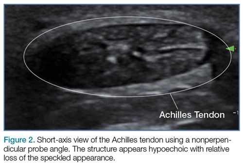
Ultrasound confirmed a complete tear of the UCL, which was flipped in a proximal direction and projected dorsally in relation to the direct insertion of the adductor tendon (Figure 2B). MRI showed focal disruption of the UCL at the level of the left thumb MCP joint with associated MCP joint effusion (Figures 4A-4F).
Low T1 signal intensity over the adductor aponeurosis at the level of the metacarpal head corresponded with the torn and proximally retracted UCL. There was associated bone marrow edema at the radial and volar aspects of the thumb metacarpal head and low-grade strain of the abductor pollicis brevis. The thumb flexor and extensor tendons appeared normal. Although possibly secondary to patient positioning, mild volar subluxation of the proximal phalanx in relation to the metacarpal head was queried.
Surgical Findings
Given laxity with pain at the UCL on stress testing, MRI and ultrasound findings, and continued pain and instability of the thumb with pinching and grasping during activities of daily living, the patient and orthopedic hand surgeon proceeded with surgical intervention. Preoperative examination under anesthesia confirmed significant laxity on valgus stress without a palpable endpoint (Figures 5A, 5B).
During surgery, retraction of the extensor hood revealed the completely torn and displaced UCL, entrapped dorsally and proximally to the adductor aponeurosis, characteristic of a Stener lesion. After the primary repair of the UCL, the extensor hood was seen partially retracted in a normal location superficial to the normal deep position of the repaired UCL (Figures 6A, 6B).
Discussion
Hyperabduction injuries to the thumb may rupture the UCL of the MCP joint of the thumb or cause a bony avulsion of the base of the proximal phalanx. Injury to the UCL, most often at its distal portion,4,14,15 may result in a sprain or full-thickness tear of the ligament.
Subsequently, the ligament may remain in situ, or the proximal segment may retract proximal to the adductor aponeurosis with continued abduction of the thumb. On release of the abduction force, the proximal UCL segment is displaced dorsally and proximally by the inferior aspect of the adductor aponeurosis. The UCL becomes entrapped by the adductor aponeurosis and cannot reduce spontaneously.15 This displacement was initially described by Stener6 in 1962 and is referred to as a Stener lesion (Figures 1A-1C).
It is vital for the radiologist to identify a Stener lesion because a nondisplaced tear of the UCL is often treated nonsurgically, but UCL tears displaced more than 3 mm and Stener lesions usually must be operated on to avoid chronic instability, pain, and osteoarthritis.2-5,8,12-23 Sensitivity and specificity of MRI in evaluating UCL injuries are reported to be almost 100%, with resolution of 1 mm using current surface coils.23 There are various UCL injury patterns, including partial tears, displaced and nondisplaced complete tears, and even complex injuries, such as an incomplete tear with the torn portion retracted as a Stener lesion.22 MRI is needed to establish the extent of injury, as 90% of complete tears that are displaced at least 3 mm, and all tears with retraction proximal and superficial to the aponeurosis (true Stener lesions), failed immobilization and required surgical treatment.23Although they vary in the literature, mean sensitivity and specificity of ultrasound in detecting UCL tears in level I studies have been reported as 76% and 81%, respectively.24 When Melville and colleagues21 applied their ultrasound criteria—including absence of normal UCL fibers traversing the first MCP joint as well as heterogeneous masslike tissue at least partially proximal to the apex of the metacarpal lateral tubercle—they were able to distinguish displaced full-thickness tears from nondisplaced full-thickness tears with 100% accuracy. Hergan and colleagues25 found that the diagnostic accuracy of MRI was superior to that of ultrasound; while MRI accuracy was perfect, 12% of patients were incorrectly diagnosed with ultrasound, with false-positive or false-negative tendon-edge displacement. In our experience, ultrasound is uniquely useful in its ability to characterize the real-time dynamic interaction of the UCL with the adductor aponeurosis. It has been observed that passive flexion of the first interphalangeal joint moves the adductor aponeurosis in isolation, allowing differentiation from the subjacent UCL.21 Had a partial tear been in the differential diagnosis of our patient’s Stener lesion, such a maneuver under ultrasound visualization would have solved the dilemma. In addition, ultrasound allows for comparison with the contralateral ligament at the time of examination should a diagnostic dilemma arise.
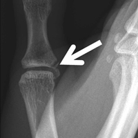
As many have reported both bony avulsion of the base of the proximal phalanx and concomitant injury to the UCL, identification of a bony avulsion does not exclude a ligamentous injury and the possibility of a Stener lesion (Figure 7).16,19
In one study, 14% of patients with injury to the UCL sustained a concomitant bony avulsion of the UCL insertion.23 However, presence of the avulsion fragment did not alter management, and only those fragments involving more than 20% of the articular surface were considered true fractures and treated as such.
Conclusion
A Stener lesion—retraction of a completely torn UCL becoming entrapped dorsally and proximally to the adductor insertion—can cause pain, instability, and ultimately osteoarthritis if not treated appropriately. The orthopedic surgeon should have a high index of suspicion for a Stener lesion in the appropriate clinical scenario and consider all imaging modalities for diagnosis. Likewise, it is of utmost importance for the radiologist to identify imaging findings of a Stener lesion, as physical examination alone may be limited in its ability to characterize injury severity. Both MRI and ultrasound are useful in evaluating UCL tears, and ultrasound provides the additional benefit of dynamic visualization and comparison with the contralateral side.
Am J Orthop. 2017;46(3):E195-E199. Copyright Frontline Medical Communications Inc. 2017. All rights reserved.
2. Anderson D. Skier’s thumb. Aust Family Physician. 2010;39(8):575-577.
3. Heim D. The skier’s thumb. Acta Orthop Belg. 1999;65(4):440-446.
4. Lohman M, Vasenius J, Kivisaari A, Kivisaari L. MR imaging in chronic rupture of the ulnar collateral ligament of the thumb. Acta Radiol. 2001;42(1):10-14.
5. Kundu N, Asfaw S, Polster J, Lohman R. The Stener lesion. Eplasty. 2012;12:ic11.
6. Stener B. Displacement of the ruptured ulnar collateral ligament of the metacarpophalangeal joint of the thumb. J Bone Joint Surg Br. 1962;44:869-879.
7. Carlson MG, Warner KK, Meyers KN, Hearns KA, Kok PL. Anatomy of the thumb metacarpophalangeal ulnar and radial collateral ligaments. J Hand Surg Am. 2012;37(10):2021-2026.
8. Heyman P. Injuries to the ulnar collateral ligament of the thumb metacarpophalangeal joint. J Am Acad Orthop Surg. 1997;5(4):224-229.
9. Minami A, An KN, Cooney WP 3rd, Linscheid RL, Chao EY. Ligamentous structures of the metacarpophalangeal joint: a quantitative anatomic study. J Orthop Res. 1984;1(4):361-368.
10. Heyman P, Gelberman RH, Duncan K, Hipp JA. Injuries of the ulnar collateral ligament of the thumb metacarpophalangeal joint. Biomechanical and prospective clinical studies on the usefulness of valgus stress testing. Clin Orthop Relat Res. 1993;(292):165-171.
11. Patel S, Potty A, Taylor EJ, Sorene ED. Collateral ligament injuries of the metacarpophalangeal joint of the thumb: a treatment algorithm. Strategies Trauma Limb Reconstr. 2010;5(1):1-10.
12. O’Callaghan BI, Kohut G, Hoogewoud HM. Gamekeeper thumb: identification of the Stener lesion with US. Radiology. 1994;192(2):477-480.
13. Ebrahim FS, De Maeseneer M, Jager T, Marcelis S, Jamadar DA, Jacobson JA. US diagnosis of UCL tears of the thumb and Stener lesions: technique, pattern-based approach, and differential diagnosis. Radiographics. 2006;26(4):1007-1020.
14. Haramati N, Hiller N, Dowdle J, et al. MRI of the Stener lesion. Skeletal Radiol. 1995;24(7):515-518.
15. Shinohara T, Horii E, Majima M, et al. Sonographic diagnosis of acute injuries of the ulnar collateral ligament of the metacarpophalangeal joint of the thumb. J Clin Ultrasound. 2007;35(2):73-77.
16. Giele H, Martin J. The two-level ulnar collateral ligament injury of the metacarpophalangeal joint of the thumb. J Hand Surg Br. 2003;28(1):92-93.
17. Kaplan SJ. The Stener lesion revisited: a case report. J Hand Surg Am. 1998;23(5):833-836.
18. Thirkannad S, Wolff TW. The “two fleck sign” for an occult Stener lesion. J Hand Surg Eur Vol. 2008;33(2):208-211.
19. Badawi RA, Hussain S, Compson JP. Two in one: a variant of the Stener lesion. Injury. 2002;33(4):379-380.
20. McKeon KE, Gelberman RH, Calfee RP. Ulnar collateral ligament injuries of the thumb: phalangeal translation during valgus stress in human cadavera. J Bone Joint Surg Am. 2013;95(10):881-887.
21. Melville D, Jacobson JA, Haase S, Brandon C, Brigido MK, Fessell D. Ultrasound of displaced ulnar collateral ligament tears of the thumb: the Stener lesion revisited. Skeletal Radiol. 2013;42(5):667-673.
22. Romano WM, Garvin G, Bhayana D, Chaudhary O. The spectrum of ulnar collateral ligament injuries as viewed on magnetic resonance imaging of the metacarpophalangeal joint of the thumb. Can Assoc Radiol J. 2003;54(4):243-248.
23. Milner CS, Manon-Matos Y, Thirkannad SM. Gamekeeper’s thumb—a treatment-oriented magnetic resonance imaging classification. J Hand Surg Am. 2015;40(1):90-95.
24. Papandrea RF, Fowler T. Injury at the thumb UCL: is there a Stener lesion? J Hand Surg Am. 2008;33(10):1882-1884.
25. Hergan K, Mittler C, Oser W. Ulnar collateral ligament: differentiation of displaced and nondisplaced tears with US and MR imaging. Radiology. 1995;194(1):65-71.
Torn, displaced, and entrapped UCL is a Stener lesion.
Hyperabduction injury with pain and joint laxity on examination.
MRI and ultrasound are useful in evaluating UCL tears.
Ultrasound offers dynamic evaluation.
Must be treated appropriately to avoid pain, instability, and osteoarthritis.
In the literature, hyperabduction injuries to the thumb metacarpophalangeal (MCP) joint have been referred to interchangeably as gamekeeper’s thumb and skier’s thumb. Historically, though, gamekeeper’s thumb was initially described in hunters with chronic injury to the ulnar collateral ligament (UCL),1 and skier’s thumb typically has been described as an acute hyperabduction injury of the UCL.2-5 The proximal portion of a torn UCL may retract with further abduction and displace dorsally, becoming entrapped by the adductor pollicis aponeurosis insertion, known as a Stener lesion.6
The first MCP joint is stabilized by static and dynamic structures that contribute in varying degrees in flexion and extension of the joint. The static stabilizers include the proper and accessory radial and UCLs, the palmar plate, and the dorsal capsule. The UCL originates at the dorsal ulnar aspect of the first metacarpal head at the metacarpal tubercle about 5 mm proximal to the articular surface. The UCL courses distally in the palmar direction to insert volar and proximal to the medial tubercle of the proximal phalanx about 3 mm distal to the articular surface.7 In flexion, the proper collateral ligament is taut and is the primary static stabilizer. In extension, the accessory collateral ligament, which inserts on the palmar plate, is taut and is the primary static stabilizer.8-11
The dynamic stabilizers include the extrinsic muscles (flexor pollicis longus, extensor pollicis longus and brevis) and the intrinsic muscles (abductor pollicis brevis, adductor pollicis, flexor pollicis brevis) inserting on the thumb at the distal phalanx and proximal phalanx and at the base of the first metacarpal.8-10
The adductor pollicis originates from the volar third metacarpal, capitate, and hamate and has a dual insertion on the thumb.12 There is a direct insertion onto the palmar proximal phalanx at the medial tubercle, distal and dorsal to the phalangeal insertion of the UCL.
There is also a broad aponeurosis that inserts onto the extensor hood expansion, dorsal to the insertion of the UCL (Figures 1A-1C and 2A, 2B).7,8,13
We report the case of an acute hyperabduction injury of the thumb MCP joint with radiographic, ultrasound, and magnetic resonance imaging (MRI) findings consistent with a Stener lesion and subsequently confirmed with intraoperative photographs. The patient provided written informed consent for print and electronic publication of this case report.
Clinical Findings
A 33-year-old healthy man had persistent left hand pain and grip weakness after performing a handstand. He presented to the orthopedic hand clinic 20 days after injury, having failed nonoperative management (use of nonsteroidal anti-inflammatory drugs and soft thumb spica splint). Physical examination revealed soft-tissue swelling and focal tenderness to palpation at the ulnar aspect of the thumb MCP joint. Despite bilateral first MCP joint laxity on varus and valgus stress without identification of a firm endpoint, pain was elicited only on valgus stress of the left first MCP joint. Given the laxity and the left thumb soft-tissue swelling with pain, plain radiographs, ultrasound, and MRI were used to evaluate for severity of presumed left thumb UCL injury.
Imaging Findings
Plain radiographs showed normal bony anatomy without fracture, normal joint space, and mild soft-tissue swelling at the left thumb MCP level (Figures 3A, 3B).
Ultrasound confirmed a complete tear of the UCL, which was flipped in a proximal direction and projected dorsally in relation to the direct insertion of the adductor tendon (Figure 2B). MRI showed focal disruption of the UCL at the level of the left thumb MCP joint with associated MCP joint effusion (Figures 4A-4F).
Low T1 signal intensity over the adductor aponeurosis at the level of the metacarpal head corresponded with the torn and proximally retracted UCL. There was associated bone marrow edema at the radial and volar aspects of the thumb metacarpal head and low-grade strain of the abductor pollicis brevis. The thumb flexor and extensor tendons appeared normal. Although possibly secondary to patient positioning, mild volar subluxation of the proximal phalanx in relation to the metacarpal head was queried.
Surgical Findings
Given laxity with pain at the UCL on stress testing, MRI and ultrasound findings, and continued pain and instability of the thumb with pinching and grasping during activities of daily living, the patient and orthopedic hand surgeon proceeded with surgical intervention. Preoperative examination under anesthesia confirmed significant laxity on valgus stress without a palpable endpoint (Figures 5A, 5B).
During surgery, retraction of the extensor hood revealed the completely torn and displaced UCL, entrapped dorsally and proximally to the adductor aponeurosis, characteristic of a Stener lesion. After the primary repair of the UCL, the extensor hood was seen partially retracted in a normal location superficial to the normal deep position of the repaired UCL (Figures 6A, 6B).
Discussion
Hyperabduction injuries to the thumb may rupture the UCL of the MCP joint of the thumb or cause a bony avulsion of the base of the proximal phalanx. Injury to the UCL, most often at its distal portion,4,14,15 may result in a sprain or full-thickness tear of the ligament.
Subsequently, the ligament may remain in situ, or the proximal segment may retract proximal to the adductor aponeurosis with continued abduction of the thumb. On release of the abduction force, the proximal UCL segment is displaced dorsally and proximally by the inferior aspect of the adductor aponeurosis. The UCL becomes entrapped by the adductor aponeurosis and cannot reduce spontaneously.15 This displacement was initially described by Stener6 in 1962 and is referred to as a Stener lesion (Figures 1A-1C).
It is vital for the radiologist to identify a Stener lesion because a nondisplaced tear of the UCL is often treated nonsurgically, but UCL tears displaced more than 3 mm and Stener lesions usually must be operated on to avoid chronic instability, pain, and osteoarthritis.2-5,8,12-23 Sensitivity and specificity of MRI in evaluating UCL injuries are reported to be almost 100%, with resolution of 1 mm using current surface coils.23 There are various UCL injury patterns, including partial tears, displaced and nondisplaced complete tears, and even complex injuries, such as an incomplete tear with the torn portion retracted as a Stener lesion.22 MRI is needed to establish the extent of injury, as 90% of complete tears that are displaced at least 3 mm, and all tears with retraction proximal and superficial to the aponeurosis (true Stener lesions), failed immobilization and required surgical treatment.23Although they vary in the literature, mean sensitivity and specificity of ultrasound in detecting UCL tears in level I studies have been reported as 76% and 81%, respectively.24 When Melville and colleagues21 applied their ultrasound criteria—including absence of normal UCL fibers traversing the first MCP joint as well as heterogeneous masslike tissue at least partially proximal to the apex of the metacarpal lateral tubercle—they were able to distinguish displaced full-thickness tears from nondisplaced full-thickness tears with 100% accuracy. Hergan and colleagues25 found that the diagnostic accuracy of MRI was superior to that of ultrasound; while MRI accuracy was perfect, 12% of patients were incorrectly diagnosed with ultrasound, with false-positive or false-negative tendon-edge displacement. In our experience, ultrasound is uniquely useful in its ability to characterize the real-time dynamic interaction of the UCL with the adductor aponeurosis. It has been observed that passive flexion of the first interphalangeal joint moves the adductor aponeurosis in isolation, allowing differentiation from the subjacent UCL.21 Had a partial tear been in the differential diagnosis of our patient’s Stener lesion, such a maneuver under ultrasound visualization would have solved the dilemma. In addition, ultrasound allows for comparison with the contralateral ligament at the time of examination should a diagnostic dilemma arise.
As many have reported both bony avulsion of the base of the proximal phalanx and concomitant injury to the UCL, identification of a bony avulsion does not exclude a ligamentous injury and the possibility of a Stener lesion (Figure 7).16,19
In one study, 14% of patients with injury to the UCL sustained a concomitant bony avulsion of the UCL insertion.23 However, presence of the avulsion fragment did not alter management, and only those fragments involving more than 20% of the articular surface were considered true fractures and treated as such.
Conclusion
A Stener lesion—retraction of a completely torn UCL becoming entrapped dorsally and proximally to the adductor insertion—can cause pain, instability, and ultimately osteoarthritis if not treated appropriately. The orthopedic surgeon should have a high index of suspicion for a Stener lesion in the appropriate clinical scenario and consider all imaging modalities for diagnosis. Likewise, it is of utmost importance for the radiologist to identify imaging findings of a Stener lesion, as physical examination alone may be limited in its ability to characterize injury severity. Both MRI and ultrasound are useful in evaluating UCL tears, and ultrasound provides the additional benefit of dynamic visualization and comparison with the contralateral side.
Am J Orthop. 2017;46(3):E195-E199. Copyright Frontline Medical Communications Inc. 2017. All rights reserved.
Take-Home Points
Torn, displaced, and entrapped UCL is a Stener lesion.
Hyperabduction injury with pain and joint laxity on examination.
MRI and ultrasound are useful in evaluating UCL tears.
Ultrasound offers dynamic evaluation.
Must be treated appropriately to avoid pain, instability, and osteoarthritis.
In the literature, hyperabduction injuries to the thumb metacarpophalangeal (MCP) joint have been referred to interchangeably as gamekeeper’s thumb and skier’s thumb. Historically, though, gamekeeper’s thumb was initially described in hunters with chronic injury to the ulnar collateral ligament (UCL),1 and skier’s thumb typically has been described as an acute hyperabduction injury of the UCL.2-5 The proximal portion of a torn UCL may retract with further abduction and displace dorsally, becoming entrapped by the adductor pollicis aponeurosis insertion, known as a Stener lesion.6
The first MCP joint is stabilized by static and dynamic structures that contribute in varying degrees in flexion and extension of the joint. The static stabilizers include the proper and accessory radial and UCLs, the palmar plate, and the dorsal capsule. The UCL originates at the dorsal ulnar aspect of the first metacarpal head at the metacarpal tubercle about 5 mm proximal to the articular surface. The UCL courses distally in the palmar direction to insert volar and proximal to the medial tubercle of the proximal phalanx about 3 mm distal to the articular surface.7 In flexion, the proper collateral ligament is taut and is the primary static stabilizer. In extension, the accessory collateral ligament, which inserts on the palmar plate, is taut and is the primary static stabilizer.8-11
The dynamic stabilizers include the extrinsic muscles (flexor pollicis longus, extensor pollicis longus and brevis) and the intrinsic muscles (abductor pollicis brevis, adductor pollicis, flexor pollicis brevis) inserting on the thumb at the distal phalanx and proximal phalanx and at the base of the first metacarpal.8-10
The adductor pollicis originates from the volar third metacarpal, capitate, and hamate and has a dual insertion on the thumb.12 There is a direct insertion onto the palmar proximal phalanx at the medial tubercle, distal and dorsal to the phalangeal insertion of the UCL.
There is also a broad aponeurosis that inserts onto the extensor hood expansion, dorsal to the insertion of the UCL (Figures 1A-1C and 2A, 2B).7,8,13
We report the case of an acute hyperabduction injury of the thumb MCP joint with radiographic, ultrasound, and magnetic resonance imaging (MRI) findings consistent with a Stener lesion and subsequently confirmed with intraoperative photographs. The patient provided written informed consent for print and electronic publication of this case report.
Clinical Findings
A 33-year-old healthy man had persistent left hand pain and grip weakness after performing a handstand. He presented to the orthopedic hand clinic 20 days after injury, having failed nonoperative management (use of nonsteroidal anti-inflammatory drugs and soft thumb spica splint). Physical examination revealed soft-tissue swelling and focal tenderness to palpation at the ulnar aspect of the thumb MCP joint. Despite bilateral first MCP joint laxity on varus and valgus stress without identification of a firm endpoint, pain was elicited only on valgus stress of the left first MCP joint. Given the laxity and the left thumb soft-tissue swelling with pain, plain radiographs, ultrasound, and MRI were used to evaluate for severity of presumed left thumb UCL injury.
Imaging Findings
Plain radiographs showed normal bony anatomy without fracture, normal joint space, and mild soft-tissue swelling at the left thumb MCP level (Figures 3A, 3B).
Ultrasound confirmed a complete tear of the UCL, which was flipped in a proximal direction and projected dorsally in relation to the direct insertion of the adductor tendon (Figure 2B). MRI showed focal disruption of the UCL at the level of the left thumb MCP joint with associated MCP joint effusion (Figures 4A-4F).
Low T1 signal intensity over the adductor aponeurosis at the level of the metacarpal head corresponded with the torn and proximally retracted UCL. There was associated bone marrow edema at the radial and volar aspects of the thumb metacarpal head and low-grade strain of the abductor pollicis brevis. The thumb flexor and extensor tendons appeared normal. Although possibly secondary to patient positioning, mild volar subluxation of the proximal phalanx in relation to the metacarpal head was queried.
Surgical Findings
Given laxity with pain at the UCL on stress testing, MRI and ultrasound findings, and continued pain and instability of the thumb with pinching and grasping during activities of daily living, the patient and orthopedic hand surgeon proceeded with surgical intervention. Preoperative examination under anesthesia confirmed significant laxity on valgus stress without a palpable endpoint (Figures 5A, 5B).
During surgery, retraction of the extensor hood revealed the completely torn and displaced UCL, entrapped dorsally and proximally to the adductor aponeurosis, characteristic of a Stener lesion. After the primary repair of the UCL, the extensor hood was seen partially retracted in a normal location superficial to the normal deep position of the repaired UCL (Figures 6A, 6B).
Discussion
Hyperabduction injuries to the thumb may rupture the UCL of the MCP joint of the thumb or cause a bony avulsion of the base of the proximal phalanx. Injury to the UCL, most often at its distal portion,4,14,15 may result in a sprain or full-thickness tear of the ligament.
Subsequently, the ligament may remain in situ, or the proximal segment may retract proximal to the adductor aponeurosis with continued abduction of the thumb. On release of the abduction force, the proximal UCL segment is displaced dorsally and proximally by the inferior aspect of the adductor aponeurosis. The UCL becomes entrapped by the adductor aponeurosis and cannot reduce spontaneously.15 This displacement was initially described by Stener6 in 1962 and is referred to as a Stener lesion (Figures 1A-1C).
It is vital for the radiologist to identify a Stener lesion because a nondisplaced tear of the UCL is often treated nonsurgically, but UCL tears displaced more than 3 mm and Stener lesions usually must be operated on to avoid chronic instability, pain, and osteoarthritis.2-5,8,12-23 Sensitivity and specificity of MRI in evaluating UCL injuries are reported to be almost 100%, with resolution of 1 mm using current surface coils.23 There are various UCL injury patterns, including partial tears, displaced and nondisplaced complete tears, and even complex injuries, such as an incomplete tear with the torn portion retracted as a Stener lesion.22 MRI is needed to establish the extent of injury, as 90% of complete tears that are displaced at least 3 mm, and all tears with retraction proximal and superficial to the aponeurosis (true Stener lesions), failed immobilization and required surgical treatment.23Although they vary in the literature, mean sensitivity and specificity of ultrasound in detecting UCL tears in level I studies have been reported as 76% and 81%, respectively.24 When Melville and colleagues21 applied their ultrasound criteria—including absence of normal UCL fibers traversing the first MCP joint as well as heterogeneous masslike tissue at least partially proximal to the apex of the metacarpal lateral tubercle—they were able to distinguish displaced full-thickness tears from nondisplaced full-thickness tears with 100% accuracy. Hergan and colleagues25 found that the diagnostic accuracy of MRI was superior to that of ultrasound; while MRI accuracy was perfect, 12% of patients were incorrectly diagnosed with ultrasound, with false-positive or false-negative tendon-edge displacement. In our experience, ultrasound is uniquely useful in its ability to characterize the real-time dynamic interaction of the UCL with the adductor aponeurosis. It has been observed that passive flexion of the first interphalangeal joint moves the adductor aponeurosis in isolation, allowing differentiation from the subjacent UCL.21 Had a partial tear been in the differential diagnosis of our patient’s Stener lesion, such a maneuver under ultrasound visualization would have solved the dilemma. In addition, ultrasound allows for comparison with the contralateral ligament at the time of examination should a diagnostic dilemma arise.
As many have reported both bony avulsion of the base of the proximal phalanx and concomitant injury to the UCL, identification of a bony avulsion does not exclude a ligamentous injury and the possibility of a Stener lesion (Figure 7).16,19
In one study, 14% of patients with injury to the UCL sustained a concomitant bony avulsion of the UCL insertion.23 However, presence of the avulsion fragment did not alter management, and only those fragments involving more than 20% of the articular surface were considered true fractures and treated as such.
Conclusion
A Stener lesion—retraction of a completely torn UCL becoming entrapped dorsally and proximally to the adductor insertion—can cause pain, instability, and ultimately osteoarthritis if not treated appropriately. The orthopedic surgeon should have a high index of suspicion for a Stener lesion in the appropriate clinical scenario and consider all imaging modalities for diagnosis. Likewise, it is of utmost importance for the radiologist to identify imaging findings of a Stener lesion, as physical examination alone may be limited in its ability to characterize injury severity. Both MRI and ultrasound are useful in evaluating UCL tears, and ultrasound provides the additional benefit of dynamic visualization and comparison with the contralateral side.
Am J Orthop. 2017;46(3):E195-E199. Copyright Frontline Medical Communications Inc. 2017. All rights reserved.
2. Anderson D. Skier’s thumb. Aust Family Physician. 2010;39(8):575-577.
3. Heim D. The skier’s thumb. Acta Orthop Belg. 1999;65(4):440-446.
4. Lohman M, Vasenius J, Kivisaari A, Kivisaari L. MR imaging in chronic rupture of the ulnar collateral ligament of the thumb. Acta Radiol. 2001;42(1):10-14.
5. Kundu N, Asfaw S, Polster J, Lohman R. The Stener lesion. Eplasty. 2012;12:ic11.
6. Stener B. Displacement of the ruptured ulnar collateral ligament of the metacarpophalangeal joint of the thumb. J Bone Joint Surg Br. 1962;44:869-879.
7. Carlson MG, Warner KK, Meyers KN, Hearns KA, Kok PL. Anatomy of the thumb metacarpophalangeal ulnar and radial collateral ligaments. J Hand Surg Am. 2012;37(10):2021-2026.
8. Heyman P. Injuries to the ulnar collateral ligament of the thumb metacarpophalangeal joint. J Am Acad Orthop Surg. 1997;5(4):224-229.
9. Minami A, An KN, Cooney WP 3rd, Linscheid RL, Chao EY. Ligamentous structures of the metacarpophalangeal joint: a quantitative anatomic study. J Orthop Res. 1984;1(4):361-368.
10. Heyman P, Gelberman RH, Duncan K, Hipp JA. Injuries of the ulnar collateral ligament of the thumb metacarpophalangeal joint. Biomechanical and prospective clinical studies on the usefulness of valgus stress testing. Clin Orthop Relat Res. 1993;(292):165-171.
11. Patel S, Potty A, Taylor EJ, Sorene ED. Collateral ligament injuries of the metacarpophalangeal joint of the thumb: a treatment algorithm. Strategies Trauma Limb Reconstr. 2010;5(1):1-10.
12. O’Callaghan BI, Kohut G, Hoogewoud HM. Gamekeeper thumb: identification of the Stener lesion with US. Radiology. 1994;192(2):477-480.
13. Ebrahim FS, De Maeseneer M, Jager T, Marcelis S, Jamadar DA, Jacobson JA. US diagnosis of UCL tears of the thumb and Stener lesions: technique, pattern-based approach, and differential diagnosis. Radiographics. 2006;26(4):1007-1020.
14. Haramati N, Hiller N, Dowdle J, et al. MRI of the Stener lesion. Skeletal Radiol. 1995;24(7):515-518.
15. Shinohara T, Horii E, Majima M, et al. Sonographic diagnosis of acute injuries of the ulnar collateral ligament of the metacarpophalangeal joint of the thumb. J Clin Ultrasound. 2007;35(2):73-77.
16. Giele H, Martin J. The two-level ulnar collateral ligament injury of the metacarpophalangeal joint of the thumb. J Hand Surg Br. 2003;28(1):92-93.
17. Kaplan SJ. The Stener lesion revisited: a case report. J Hand Surg Am. 1998;23(5):833-836.
18. Thirkannad S, Wolff TW. The “two fleck sign” for an occult Stener lesion. J Hand Surg Eur Vol. 2008;33(2):208-211.
19. Badawi RA, Hussain S, Compson JP. Two in one: a variant of the Stener lesion. Injury. 2002;33(4):379-380.
20. McKeon KE, Gelberman RH, Calfee RP. Ulnar collateral ligament injuries of the thumb: phalangeal translation during valgus stress in human cadavera. J Bone Joint Surg Am. 2013;95(10):881-887.
21. Melville D, Jacobson JA, Haase S, Brandon C, Brigido MK, Fessell D. Ultrasound of displaced ulnar collateral ligament tears of the thumb: the Stener lesion revisited. Skeletal Radiol. 2013;42(5):667-673.
22. Romano WM, Garvin G, Bhayana D, Chaudhary O. The spectrum of ulnar collateral ligament injuries as viewed on magnetic resonance imaging of the metacarpophalangeal joint of the thumb. Can Assoc Radiol J. 2003;54(4):243-248.
23. Milner CS, Manon-Matos Y, Thirkannad SM. Gamekeeper’s thumb—a treatment-oriented magnetic resonance imaging classification. J Hand Surg Am. 2015;40(1):90-95.
24. Papandrea RF, Fowler T. Injury at the thumb UCL: is there a Stener lesion? J Hand Surg Am. 2008;33(10):1882-1884.
25. Hergan K, Mittler C, Oser W. Ulnar collateral ligament: differentiation of displaced and nondisplaced tears with US and MR imaging. Radiology. 1995;194(1):65-71.
A 20-year-old woman with no significant medical history presented to the ED with a several-month history of worsening abdominal pain. She reported that although she previously had been evaluated at multiple EDs, no cause of her abdominal pain had been identified. The patient further noted that the pain had significantly increased the day of this presentation.
Figure 1
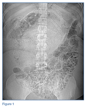
Physical examination revealed guarding and rebound tenderness in the midabdomen. Computed tomography (CT) studies of the abdomen and pelvis were performed; representative scout and axial images of the upper abdomen are shown above (Figures 1 and 2).
Figure 2
What is the suspected diagnosis?
Answer
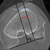
The scout image of the abdomen revealed a distended stomach (white arrows, Figure 3), which displaced multiple loops of small bowel into the lower abdomen. The axial image through the upper abdomen showed air and solid material within the distended stomach (white arrows, Figure 4). Multiple foci of extraluminal (free) air were seen anteriorly (white asterisks, Figure 4). A coronal reformat of the CT better demonstrated the distended stomach filled with debris (white arrows, Figure 5), extraluminal air (white asterisk, Figure 5), and pneumatosis (air within the walls of multiple small bowel loops; red arrows, Figure 5).
These findings indicated a bowel obstruction and perforation due to the presence of a gastric bezoar. Upon further questioning, the patient admitted to a stress-related habit of eating her own hair (trichophagia) over the past 3 to 4 months.
Figure 3
Bezoars
Gastric bezoars are aggregates of nondigestible material that collect within the gastrointestinal system, usually fruit/vegetable matter (phytobezoars) or hair (trichobezoars). Phytobezoars are most common in patients with a history of reduced gastric motility and/or prior gastric surgery. Trichobezoars, similar to the one seen in this case, typically occur in young women and/or patients with psychiatric illness.1
Gastric bezoars are typically located in the gastric body but may extend into the small bowel and cause bowel obstruction. Trichobezoars that extend into the small bowel are referred to as “Rapunzel syndrome” (based on the fairy tale of the princess with long hair).
Figure 4
Clinical Presentation
Patients with gastric bezoars often present to the ED with nonspecific complaints of abdominal pain, including early satiety, weight loss, signs of anemia, abdominal pain, bloating, and symptoms of small bowel obstruction (SBO).2 Obtaining a thorough history is important to identify trichophagia, as only a small percentage of patients have evidence of alopecia on examination.
Figure 5
Workup
The workup for patients with gastric bezoars typically involves multiple imaging modalities. While abdominal radiography may demonstrate distention of the stomach, these findings are often nonspecific, and the characteristic feature of a mass with a diffusely mottled appearance is visualized in less than 20% of cases.
Computed tomography is the test of choice for detecting a bezoar, with a reported sensitivity of 97%.3 This modality is also useful for assessing the size of a bezoar and evaluating for complications such as SBO, perforation (free-air), or pneumatosis—all of which were revealed on this patient’s CT studies.
Treatment
The treatment for patients with large or obstructing gastric bezoars is surgical resection; both open and laparoscopic techniques have been described in the literature.2,4 The patient in this case was admitted to the hospital, where she underwent surgical removal of the bezoar. She was discharged home on hospital day 6 with outpatient psychiatric follow-up.
References
1. Guniganti P, Bradenham CH, Raptis C, Menias CO, Mellnick VM. Radiographics. 2015;35(7):1909-1921. doi:10.1148/rg.2015150062. 2. Fallon SC, Slater BJ, Larimer EL, Brandt ML, Lopez ME. The surgical management of Rapunzel syndrome: a case series and literature review. J Pediatr Surg. 2013;48(4):830-834. doi:10.1016/j.jpedsurg.2012.07.046. 3. Ripollés T, García-Aguayo J, Martínez MJ, Gil P. Gastrointestinal Bezoars: Sonographic and CT Characteristics. AJR Am J Roentgenol. 2001;177(1):65-69. doi:10.2214/ajr.177.1.1770065. 4. Flaherty DC, Aguilar F, Pradhan B, Grewal H. Rapunzel syndrome due to ingested hair extensions: Surgical and psychiatric considerations. Int J Surg Case Rep. 2015;17:155-157. doi:10.1016/j.ijscr.2015.11.009.
An otherwise healthy 20-year-old woman presented for evaluation of severe chronic abdominal pain.
An otherwise healthy 20-year-old woman presented for evaluation of severe chronic abdominal pain.
A 20-year-old woman with no significant medical history presented to the ED with a several-month history of worsening abdominal pain. She reported that although she previously had been evaluated at multiple EDs, no cause of her abdominal pain had been identified. The patient further noted that the pain had significantly increased the day of this presentation.
Figure 1
Physical examination revealed guarding and rebound tenderness in the midabdomen. Computed tomography (CT) studies of the abdomen and pelvis were performed; representative scout and axial images of the upper abdomen are shown above (Figures 1 and 2).
Figure 2
What is the suspected diagnosis?
Answer
The scout image of the abdomen revealed a distended stomach (white arrows, Figure 3), which displaced multiple loops of small bowel into the lower abdomen. The axial image through the upper abdomen showed air and solid material within the distended stomach (white arrows, Figure 4). Multiple foci of extraluminal (free) air were seen anteriorly (white asterisks, Figure 4). A coronal reformat of the CT better demonstrated the distended stomach filled with debris (white arrows, Figure 5), extraluminal air (white asterisk, Figure 5), and pneumatosis (air within the walls of multiple small bowel loops; red arrows, Figure 5).
These findings indicated a bowel obstruction and perforation due to the presence of a gastric bezoar. Upon further questioning, the patient admitted to a stress-related habit of eating her own hair (trichophagia) over the past 3 to 4 months.
Figure 3
Bezoars
Gastric bezoars are aggregates of nondigestible material that collect within the gastrointestinal system, usually fruit/vegetable matter (phytobezoars) or hair (trichobezoars). Phytobezoars are most common in patients with a history of reduced gastric motility and/or prior gastric surgery. Trichobezoars, similar to the one seen in this case, typically occur in young women and/or patients with psychiatric illness.1
Gastric bezoars are typically located in the gastric body but may extend into the small bowel and cause bowel obstruction. Trichobezoars that extend into the small bowel are referred to as “Rapunzel syndrome” (based on the fairy tale of the princess with long hair).
Figure 4
Clinical Presentation
Patients with gastric bezoars often present to the ED with nonspecific complaints of abdominal pain, including early satiety, weight loss, signs of anemia, abdominal pain, bloating, and symptoms of small bowel obstruction (SBO).2 Obtaining a thorough history is important to identify trichophagia, as only a small percentage of patients have evidence of alopecia on examination.
Figure 5
Workup
The workup for patients with gastric bezoars typically involves multiple imaging modalities. While abdominal radiography may demonstrate distention of the stomach, these findings are often nonspecific, and the characteristic feature of a mass with a diffusely mottled appearance is visualized in less than 20% of cases.
Computed tomography is the test of choice for detecting a bezoar, with a reported sensitivity of 97%.3 This modality is also useful for assessing the size of a bezoar and evaluating for complications such as SBO, perforation (free-air), or pneumatosis—all of which were revealed on this patient’s CT studies.
Treatment
The treatment for patients with large or obstructing gastric bezoars is surgical resection; both open and laparoscopic techniques have been described in the literature.2,4 The patient in this case was admitted to the hospital, where she underwent surgical removal of the bezoar. She was discharged home on hospital day 6 with outpatient psychiatric follow-up.
References
1. Guniganti P, Bradenham CH, Raptis C, Menias CO, Mellnick VM. Radiographics. 2015;35(7):1909-1921. doi:10.1148/rg.2015150062. 2. Fallon SC, Slater BJ, Larimer EL, Brandt ML, Lopez ME. The surgical management of Rapunzel syndrome: a case series and literature review. J Pediatr Surg. 2013;48(4):830-834. doi:10.1016/j.jpedsurg.2012.07.046. 3. Ripollés T, García-Aguayo J, Martínez MJ, Gil P. Gastrointestinal Bezoars: Sonographic and CT Characteristics. AJR Am J Roentgenol. 2001;177(1):65-69. doi:10.2214/ajr.177.1.1770065. 4. Flaherty DC, Aguilar F, Pradhan B, Grewal H. Rapunzel syndrome due to ingested hair extensions: Surgical and psychiatric considerations. Int J Surg Case Rep. 2015;17:155-157. doi:10.1016/j.ijscr.2015.11.009.
To the Editor: In their Clinical Picture article in the February 2017 issue, Barbaryan et al1 describe brain lesions in a young woman with human immunodeficiency virus infection who presented with seizures. Figure 3 illustrates Grocott-Gomori methenamine silver (GMS)-positive fungal organisms in a brain biopsy. The organisms appear helmet-shaped and crescent-shaped and contain an intracystic dot, morphologic features of Pneumocystis jiroveci cysts.2 We could not appreciate features of Histoplasma yeasts (smaller yeasts with diameter of 3 to 5 μm, oval to tapered shape, and narrow-based budding).
The distinction between the two organisms can occasionally be challenging because there is some degree of overlap in size and shape, and both are GMS-positive. It is interesting that in the current case, serologic studies for Histoplasma were positive. Multiple infections with opportunistic organisms are not uncommon in severely immunocompromised individuals, and it is possible that the patient may also have had concurrent histoplasmosis. Brain lesions caused by Pneumocystis, although rare, have been previously reported.3–5 Immunohistochemistry for Pneumocystis may be of interest in this very unusual case.
[Editor’s note: Letters that comment on articles published in the Journal are sent to the author(s) for response. In this case, the authors felt that the letter did not require a reply.]
References
Barbaryan A, Modi J, Raqeem W, Choi MI, Frigy A, Mirrakhimov AE. Ring-enhancing cerebral lesions. Cleve Clin J Med 2017; 84:104–105,110.
Mukhopadhyay S, Gal AA. Granulomatous lung disease. An approach to the differential diagnosis. Arch Pathol Lab Med 2010; 134:667–690.
Mayayo E, Vidal F, Almira R, Gonzalez J, Richart C. Cerebral Pneumocystis carinii infection in AIDS. Lancet 1990; 336:1592.
Bartlett JA, Hulette C. Central nervous system pneumocystosis in a patient with AIDS. Clin Infect Dis 1997;25:82–85.
Vidal F, Mirón M, Sirvent JJ, Richart C. Central nervous system pneumocystosis in AIDS: antemortem diagnosis and successful treatment. Clin Infect Dis 2000; 30:397–398.
To the Editor: In their Clinical Picture article in the February 2017 issue, Barbaryan et al1 describe brain lesions in a young woman with human immunodeficiency virus infection who presented with seizures. Figure 3 illustrates Grocott-Gomori methenamine silver (GMS)-positive fungal organisms in a brain biopsy. The organisms appear helmet-shaped and crescent-shaped and contain an intracystic dot, morphologic features of Pneumocystis jiroveci cysts.2 We could not appreciate features of Histoplasma yeasts (smaller yeasts with diameter of 3 to 5 μm, oval to tapered shape, and narrow-based budding).
The distinction between the two organisms can occasionally be challenging because there is some degree of overlap in size and shape, and both are GMS-positive. It is interesting that in the current case, serologic studies for Histoplasma were positive. Multiple infections with opportunistic organisms are not uncommon in severely immunocompromised individuals, and it is possible that the patient may also have had concurrent histoplasmosis. Brain lesions caused by Pneumocystis, although rare, have been previously reported.3–5 Immunohistochemistry for Pneumocystis may be of interest in this very unusual case.
[Editor’s note: Letters that comment on articles published in the Journal are sent to the author(s) for response. In this case, the authors felt that the letter did not require a reply.]
References
Barbaryan A, Modi J, Raqeem W, Choi MI, Frigy A, Mirrakhimov AE. Ring-enhancing cerebral lesions. Cleve Clin J Med 2017; 84:104–105,110.
Mukhopadhyay S, Gal AA. Granulomatous lung disease. An approach to the differential diagnosis. Arch Pathol Lab Med 2010; 134:667–690.
Mayayo E, Vidal F, Almira R, Gonzalez J, Richart C. Cerebral Pneumocystis carinii infection in AIDS. Lancet 1990; 336:1592.
Bartlett JA, Hulette C. Central nervous system pneumocystosis in a patient with AIDS. Clin Infect Dis 1997;25:82–85.
Vidal F, Mirón M, Sirvent JJ, Richart C. Central nervous system pneumocystosis in AIDS: antemortem diagnosis and successful treatment. Clin Infect Dis 2000; 30:397–398.
“What imaging study should I order for this patient?” is a question that comes up frequently in the hospital. Dr. Kasprzak, the director of abdominopelvic and oncologic imaging at Case Western MetroHealth, Cleveland, offered some practical advice for inpatient clinicians during a rapid-fire session at HM17.
Dr. Raj Sehgal
Regarding the choice of imaging modality, Dr. Kasprzak recommended the use of appropriateness criteria, such as one offered by the American College of Radiology (ACR) . The ACR not only provides recommendations for the most appropriate testing for various conditions but also evidence tables and literature searches for those interested in examining the data further.
The session also touched on the risks and benefits of contrast media for CT scans and MRIs. As with other tests and treatments in medicine, the use of contrast is always a “risk-benefit.” The main benefit of both forms of contrast is to improve the “conspicuity” of findings on imaging studies – many diagnoses that are visible with contrast (such as vascular lesions, solid organ lesions, or extravasations) are invisible without it.
The risks of both CT and MRI contrast have been re-evaluated over the past several years. More recent evidence is suggesting the prevalence of contrast-induced nephropathy is lower than previously thought, especially with newer non-ionic contrast. Conversely, there is some recent evidence that CT contrast might accentuate radiation-related DNA damage. Regarding MRIs, gadolinium has been associated with nephrogenic systemic fibrosis, particularly in patients with end-stage renal disease. This appears to be less prevalent with newer gadolinium agents. There are, however, recent reports of gadolinium deposition in the basal ganglia of patients. The clinical significance of this imaging finding is still unknown.
Lastly, Dr. Kasprzak offered advice on the use of PET scans on inpatients. While there are a few indications that would warrant inpatient use (such as evaluation in fever of unknown origin), most PET scans are done for oncologic reasons that do not warrant urgent inpatient use. In addition, some insurance companies don’t reimburse for inpatient PET studies.
Key takeaways for HM
• Utilize appropriate use criteria (such as offered by the ACR) for choosing the most worthwhile imaging study.
• Give relevant clinical history in your order to help the radiologist narrow the differential (and to help prevent the “clinically correlate” phrase as much as possible).
• Consider the risk/benefit of contrast use for all patients getting CT or MRI studies.
• Avoid the use of inpatient PET scans, except for very specific indications (such as obscure infections).
Dr. Sehgal is a hospitalist at the South Texas Veterans Health Care System in San Antonio, an associate professor of medicine at University of Texas Health-San Antonio, and a an editorial board member of The Hospitalist.
Presenter
Timothy Kasprzak, MD, MBA
Session summary
“What imaging study should I order for this patient?” is a question that comes up frequently in the hospital. Dr. Kasprzak, the director of abdominopelvic and oncologic imaging at Case Western MetroHealth, Cleveland, offered some practical advice for inpatient clinicians during a rapid-fire session at HM17.
Dr. Raj Sehgal
Regarding the choice of imaging modality, Dr. Kasprzak recommended the use of appropriateness criteria, such as one offered by the American College of Radiology (ACR) . The ACR not only provides recommendations for the most appropriate testing for various conditions but also evidence tables and literature searches for those interested in examining the data further.
The session also touched on the risks and benefits of contrast media for CT scans and MRIs. As with other tests and treatments in medicine, the use of contrast is always a “risk-benefit.” The main benefit of both forms of contrast is to improve the “conspicuity” of findings on imaging studies – many diagnoses that are visible with contrast (such as vascular lesions, solid organ lesions, or extravasations) are invisible without it.
The risks of both CT and MRI contrast have been re-evaluated over the past several years. More recent evidence is suggesting the prevalence of contrast-induced nephropathy is lower than previously thought, especially with newer non-ionic contrast. Conversely, there is some recent evidence that CT contrast might accentuate radiation-related DNA damage. Regarding MRIs, gadolinium has been associated with nephrogenic systemic fibrosis, particularly in patients with end-stage renal disease. This appears to be less prevalent with newer gadolinium agents. There are, however, recent reports of gadolinium deposition in the basal ganglia of patients. The clinical significance of this imaging finding is still unknown.
Lastly, Dr. Kasprzak offered advice on the use of PET scans on inpatients. While there are a few indications that would warrant inpatient use (such as evaluation in fever of unknown origin), most PET scans are done for oncologic reasons that do not warrant urgent inpatient use. In addition, some insurance companies don’t reimburse for inpatient PET studies.
Key takeaways for HM
• Utilize appropriate use criteria (such as offered by the ACR) for choosing the most worthwhile imaging study.
• Give relevant clinical history in your order to help the radiologist narrow the differential (and to help prevent the “clinically correlate” phrase as much as possible).
• Consider the risk/benefit of contrast use for all patients getting CT or MRI studies.
• Avoid the use of inpatient PET scans, except for very specific indications (such as obscure infections).
Dr. Sehgal is a hospitalist at the South Texas Veterans Health Care System in San Antonio, an associate professor of medicine at University of Texas Health-San Antonio, and a an editorial board member of The Hospitalist.
Nilam Soni, MD, FHM; Thomas Conlon, MD; Ria Dancel, MD, FAAP, FHM; Daniel Schnobrich, MD
Summary
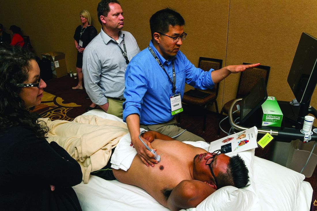
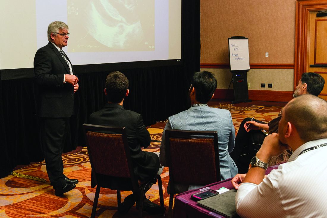
Point-of-care ultrasound (POCUS) is rapidly gaining acceptance in the medical community as a goal-directed examination that answers a specific diagnostic question or guides a bedside invasive procedure. Adoption by pediatric hospitalists is increasing, aided by multiple training pathways, opportunities for scholarship, and organization development.
The use of POCUS is increasing among nonradiologist physicians due to the expectation for perfection, desire for improved patient experience, and increased availability of ultrasound machines. POCUS is rapid and safe, and can be used serially to monitor, provide procedural guidance, and lead to initiation of appropriate therapies.
Dr. Weijen W. Chang
Training in POCUS in limited applications is possible in short periods of time. One recent study showed that approximately 40% of POCUS cases led to new findings or alteration of treatment. However, POCUS requires training, monitoring for competence, transparency of training/competence, and a QA process that supports the training. One solution at Children’s Hospital of Philadelphia was to use American College of Emergency Physician guidelines for POCUS training.
Pediatric applications include guidance of bladder catheterization, identifying occult abscesses, diagnosis of pneumonia and associated parapneumonic effusion, and IV placement. More advanced applications include diagnosis of appendicitis, intussusception, and increased intracranial pressure. Novel applications conceived by nonradiologist physicians have included sinus ultrasound.
Initial training can be provided by “in-house experts,” such as pediatric ED physicians and PICU physicians. Alternatively, an on-site commercial course can be arranged for larger groups. Consideration should be given to mentorship, with comparison to formal imaging and/or clinical progression. Relationships with traditional imagers should be cultivated, as POCUS can potentially be misunderstood. In fact, formal US utilization has been found to increase once clinicals begin to use POCUS.
Key takeaways for HM
Point-of-care ultrasound (POCUS) is rapidly being adopted by pediatric hospitalists.
Pediatric applications are still being developed, but include guidance of bladder catheterization, identifying occult abscesses, diagnosis of pneumonia/associated effusions, and IV placement.
Initial training can be provided by pediatric ED physicians/PICU physicians or an on-site commercial course can be arranged for larger groups.
Relationships with radiologists should be established at the outset to avoid misunderstanding of POCUS.
Dr. Chang is a pediatric hospitalist at Baystate Children’s Hospital and is the pediatric editor of The Hospitalist.
Nilam Soni, MD, FHM; Thomas Conlon, MD; Ria Dancel, MD, FAAP, FHM; Daniel Schnobrich, MD
Summary
Point-of-care ultrasound (POCUS) is rapidly gaining acceptance in the medical community as a goal-directed examination that answers a specific diagnostic question or guides a bedside invasive procedure. Adoption by pediatric hospitalists is increasing, aided by multiple training pathways, opportunities for scholarship, and organization development.
The use of POCUS is increasing among nonradiologist physicians due to the expectation for perfection, desire for improved patient experience, and increased availability of ultrasound machines. POCUS is rapid and safe, and can be used serially to monitor, provide procedural guidance, and lead to initiation of appropriate therapies.
Dr. Weijen W. Chang
Training in POCUS in limited applications is possible in short periods of time. One recent study showed that approximately 40% of POCUS cases led to new findings or alteration of treatment. However, POCUS requires training, monitoring for competence, transparency of training/competence, and a QA process that supports the training. One solution at Children’s Hospital of Philadelphia was to use American College of Emergency Physician guidelines for POCUS training.
Pediatric applications include guidance of bladder catheterization, identifying occult abscesses, diagnosis of pneumonia and associated parapneumonic effusion, and IV placement. More advanced applications include diagnosis of appendicitis, intussusception, and increased intracranial pressure. Novel applications conceived by nonradiologist physicians have included sinus ultrasound.
Initial training can be provided by “in-house experts,” such as pediatric ED physicians and PICU physicians. Alternatively, an on-site commercial course can be arranged for larger groups. Consideration should be given to mentorship, with comparison to formal imaging and/or clinical progression. Relationships with traditional imagers should be cultivated, as POCUS can potentially be misunderstood. In fact, formal US utilization has been found to increase once clinicals begin to use POCUS.
Key takeaways for HM
Point-of-care ultrasound (POCUS) is rapidly being adopted by pediatric hospitalists.
Pediatric applications are still being developed, but include guidance of bladder catheterization, identifying occult abscesses, diagnosis of pneumonia/associated effusions, and IV placement.
Initial training can be provided by pediatric ED physicians/PICU physicians or an on-site commercial course can be arranged for larger groups.
Relationships with radiologists should be established at the outset to avoid misunderstanding of POCUS.
Dr. Chang is a pediatric hospitalist at Baystate Children’s Hospital and is the pediatric editor of The Hospitalist.
Presenters
Nilam Soni, MD, FHM; Thomas Conlon, MD; Ria Dancel, MD, FAAP, FHM; Daniel Schnobrich, MD
Summary
Point-of-care ultrasound (POCUS) is rapidly gaining acceptance in the medical community as a goal-directed examination that answers a specific diagnostic question or guides a bedside invasive procedure. Adoption by pediatric hospitalists is increasing, aided by multiple training pathways, opportunities for scholarship, and organization development.
The use of POCUS is increasing among nonradiologist physicians due to the expectation for perfection, desire for improved patient experience, and increased availability of ultrasound machines. POCUS is rapid and safe, and can be used serially to monitor, provide procedural guidance, and lead to initiation of appropriate therapies.
Dr. Weijen W. Chang
Training in POCUS in limited applications is possible in short periods of time. One recent study showed that approximately 40% of POCUS cases led to new findings or alteration of treatment. However, POCUS requires training, monitoring for competence, transparency of training/competence, and a QA process that supports the training. One solution at Children’s Hospital of Philadelphia was to use American College of Emergency Physician guidelines for POCUS training.
Pediatric applications include guidance of bladder catheterization, identifying occult abscesses, diagnosis of pneumonia and associated parapneumonic effusion, and IV placement. More advanced applications include diagnosis of appendicitis, intussusception, and increased intracranial pressure. Novel applications conceived by nonradiologist physicians have included sinus ultrasound.
Initial training can be provided by “in-house experts,” such as pediatric ED physicians and PICU physicians. Alternatively, an on-site commercial course can be arranged for larger groups. Consideration should be given to mentorship, with comparison to formal imaging and/or clinical progression. Relationships with traditional imagers should be cultivated, as POCUS can potentially be misunderstood. In fact, formal US utilization has been found to increase once clinicals begin to use POCUS.
Key takeaways for HM
Point-of-care ultrasound (POCUS) is rapidly being adopted by pediatric hospitalists.
Pediatric applications are still being developed, but include guidance of bladder catheterization, identifying occult abscesses, diagnosis of pneumonia/associated effusions, and IV placement.
Initial training can be provided by pediatric ED physicians/PICU physicians or an on-site commercial course can be arranged for larger groups.
Relationships with radiologists should be established at the outset to avoid misunderstanding of POCUS.
Dr. Chang is a pediatric hospitalist at Baystate Children’s Hospital and is the pediatric editor of The Hospitalist.
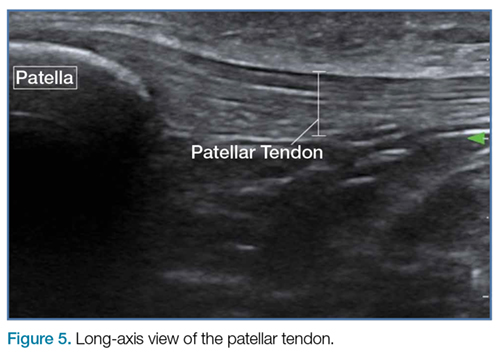
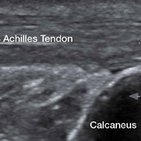
Emergency Ultrasound: Tendon Evaluation With Ultrasonography
Ultrasound provides detailed and dynamic assessment of tendons, increasing the diagnostic accuracy of injuries, especially when physical examination is equivocal.
The vast majority of musculotendinous injuries occur secondary to violent contraction or excessive stretching.1 Ligamentous injuries, on the other hand, are due to an abnormal motion of joints. The magnitude of inciting forces results in a spectrum of pathology, ranging from a minor tear to a complete disruption of structures.
Ultrasonography provides a detailed assessment of soft tissue anatomy and dynamic functionality, and in some instances can be comparable or even superior to magnetic resonance imaging2 because the structural characteristics of certain tendons make them ideal for imaging via ultrasonography. We describe some of these characteristics and highlight their utility in diagnostic imaging.
Anatomical Structure
Tendons consist of tightly packed type I collagen fibers forming subfascicles that are arranged in a parallel distribution as fascicles. These bundles are held together by loose soft tissue, and the entire structure is covered by a thick fibroelastic epitendineum sheath. This linear distribution of structures yields a uniquely linear “fibrillary” pattern when viewed along the longitudinal axis of the structure (Figure 1a). In the short-axis view, the tendon appears as a well-circumscribed structure with speckled pattern of hyperechoic foci (Figure 1b). 3
Figure 1
Imaging Technique
The optimal scanning technique involves the use of a high-frequency linear transducer. Higher frequencies yield more detailed images, but may be limited in patients with deeper structures due to body habitus. A key concept in tendon evaluation is an artifact known as “anisotropy.” This refers to change in appearance of the tendon based on the incident angle of the ultrasound beam. For example, when the probe is held perpendicular to the structure of interest, parallel fibers will reflect the emitted beam toward the probe and thus appear as hyperechoic and speckled, a characteristic of these fibers (Figures1a and 1b). Contrarily, if the probe is held at a nonperpendicular angle, the reflected beam will not return to the probe, resulting in a hypoechoic appearance (Figure 2).
Figure 2
Pathology
Tendon strains result in varying degrees of fibrous tearing. These tears can range from first-degree tears (a few fibers) to third-degree tears (complete disruption). Partial tears result in focal hematoma formation (Figure 3a) at the region of disruption, appearing on ultrasound as a hypoechoic fluid collection within a hyperechoic fibrillary or speckled tendon structure. If the disruption occurs along the surface of the tendon, a focus of anechoic fluid may be seen surrounding the tendon. Complete tendon ruptures, on the other hand, appear as a hypoechoic void with retracted tendon fragments visualized on either side4 (Figures 3b and 3c). Although complete tears can be more apparent clinically in areas in which a group of tendons performs a cohesive movement (ie, rotator cuff), ultrasound can significantly reduce the rate of delayed diagnosis when physical examination is equivocal.
Figure 3
In the appropriate clinical setting, ultrasonography can provide rapid and dynamic assessment of musculotendinous injuries. Lower extremity injuries, including those affecting the Achilles (Figure 1), quadriceps, (Figures4a and 4b) and patellar tendons (Figure 5), are easier clinical applications.
Figure 4
Assessment of rotator cuff tendons, although more difficult, can provide a specific assessment of shoulder pain.5 In such scenarios, ultrasound can serve a very useful role as an adjunct to the physical examination.
Figure 5
An important point to recognize is that tendons will appear hypoechoic at the insertion point on bone (anthesis) due to increased curvature resulting in lack of anisotropy. This can appear as a pathological finding, but can be accounted for by simply performing a heel-toe or tilt maneuver to arrange the beam perpendicular to the tendon fibers (Figures6a and 6b).
Figure 6
Summary
Musculotendinous injuries many times present as nonspecific symptoms of pain and/or swelling. In the case of an equivocal physical examination, musculotendinous injuries can be diagnosed with increased accuracy through the use of ultrasound. Understanding the artifactual component of tendon ultrasound can aid the clinician in diagnosing these injuries, enhancing patient care and satisfaction.
5. Tran G, Hensor EM, Ray A, Kingsbury SR, O’Connor P, Conaghan PG. Ultrasound-detected pathologies cluster into groups with different clinical outcomes: data from 3000 community referrals for shoulder pain. Arthritis Res Ther. 2017;19(1):30. doi:10.1186/s13075-017-1235-y.
Ultrasound provides detailed and dynamic assessment of tendons, increasing the diagnostic accuracy of injuries, especially when physical examination is equivocal.
Ultrasound provides detailed and dynamic assessment of tendons, increasing the diagnostic accuracy of injuries, especially when physical examination is equivocal.
The vast majority of musculotendinous injuries occur secondary to violent contraction or excessive stretching.1 Ligamentous injuries, on the other hand, are due to an abnormal motion of joints. The magnitude of inciting forces results in a spectrum of pathology, ranging from a minor tear to a complete disruption of structures.
Ultrasonography provides a detailed assessment of soft tissue anatomy and dynamic functionality, and in some instances can be comparable or even superior to magnetic resonance imaging2 because the structural characteristics of certain tendons make them ideal for imaging via ultrasonography. We describe some of these characteristics and highlight their utility in diagnostic imaging.
Anatomical Structure
Tendons consist of tightly packed type I collagen fibers forming subfascicles that are arranged in a parallel distribution as fascicles. These bundles are held together by loose soft tissue, and the entire structure is covered by a thick fibroelastic epitendineum sheath. This linear distribution of structures yields a uniquely linear “fibrillary” pattern when viewed along the longitudinal axis of the structure (Figure 1a). In the short-axis view, the tendon appears as a well-circumscribed structure with speckled pattern of hyperechoic foci (Figure 1b). 3
Figure 1
Imaging Technique
The optimal scanning technique involves the use of a high-frequency linear transducer. Higher frequencies yield more detailed images, but may be limited in patients with deeper structures due to body habitus. A key concept in tendon evaluation is an artifact known as “anisotropy.” This refers to change in appearance of the tendon based on the incident angle of the ultrasound beam. For example, when the probe is held perpendicular to the structure of interest, parallel fibers will reflect the emitted beam toward the probe and thus appear as hyperechoic and speckled, a characteristic of these fibers (Figures1a and 1b). Contrarily, if the probe is held at a nonperpendicular angle, the reflected beam will not return to the probe, resulting in a hypoechoic appearance (Figure 2).
Figure 2
Pathology
Tendon strains result in varying degrees of fibrous tearing. These tears can range from first-degree tears (a few fibers) to third-degree tears (complete disruption). Partial tears result in focal hematoma formation (Figure 3a) at the region of disruption, appearing on ultrasound as a hypoechoic fluid collection within a hyperechoic fibrillary or speckled tendon structure. If the disruption occurs along the surface of the tendon, a focus of anechoic fluid may be seen surrounding the tendon. Complete tendon ruptures, on the other hand, appear as a hypoechoic void with retracted tendon fragments visualized on either side4 (Figures 3b and 3c). Although complete tears can be more apparent clinically in areas in which a group of tendons performs a cohesive movement (ie, rotator cuff), ultrasound can significantly reduce the rate of delayed diagnosis when physical examination is equivocal.
Figure 3
In the appropriate clinical setting, ultrasonography can provide rapid and dynamic assessment of musculotendinous injuries. Lower extremity injuries, including those affecting the Achilles (Figure 1), quadriceps, (Figures4a and 4b) and patellar tendons (Figure 5), are easier clinical applications.
Figure 4
Assessment of rotator cuff tendons, although more difficult, can provide a specific assessment of shoulder pain.5 In such scenarios, ultrasound can serve a very useful role as an adjunct to the physical examination.
Figure 5
An important point to recognize is that tendons will appear hypoechoic at the insertion point on bone (anthesis) due to increased curvature resulting in lack of anisotropy. This can appear as a pathological finding, but can be accounted for by simply performing a heel-toe or tilt maneuver to arrange the beam perpendicular to the tendon fibers (Figures6a and 6b).
Figure 6
Summary
Musculotendinous injuries many times present as nonspecific symptoms of pain and/or swelling. In the case of an equivocal physical examination, musculotendinous injuries can be diagnosed with increased accuracy through the use of ultrasound. Understanding the artifactual component of tendon ultrasound can aid the clinician in diagnosing these injuries, enhancing patient care and satisfaction.
5. Tran G, Hensor EM, Ray A, Kingsbury SR, O’Connor P, Conaghan PG. Ultrasound-detected pathologies cluster into groups with different clinical outcomes: data from 3000 community referrals for shoulder pain. Arthritis Res Ther. 2017;19(1):30. doi:10.1186/s13075-017-1235-y.
5. Tran G, Hensor EM, Ray A, Kingsbury SR, O’Connor P, Conaghan PG. Ultrasound-detected pathologies cluster into groups with different clinical outcomes: data from 3000 community referrals for shoulder pain. Arthritis Res Ther. 2017;19(1):30. doi:10.1186/s13075-017-1235-y.
Hospitalists participated in a double-header of hands-on point-of-care ultrasound training here on Monday, looking to gain an edge in expertise in a role that’s becoming more and more common.
Nearly 100 hospitalists and other health care professionals heard talks on the fundamental principles of ultrasound and cardiac, lung and vascular, and abdominal ultrasound. The highlights of the sessions were two 80-minute hands-on segments using the probes.
“This course has grown and grown – this is the largest we’ve ever done,” said pre-course director Nilam Soni, MD, MS, FHM, associate professor of medicine at the University of Texas Health Science Center San Antonio.
Darnell Scott/Frontline Medical News
Dr. Joel Cho of the Kaiser Foundation Hospital San Francisco demonstrates the apical 4-chamber view during a hands-on training session. A morning and afternoon session were held, each attended by 48 registrants. Because of high demand, the society added 12 spots to each session – and there was still a wait list, said Ricardo Franco-Sadud, MD, the other director of the course and associate professor of medicine at the Medical College of Wisconsin, Milwaukee.
“The idea is to give you the most amount of time with the probe in their hand,” Dr. Franco said.
In one of the hands-on sessions, Adam Merando, MD, a hospitalist and associate program director of the internal medicine residency program at Saint Louis University, slid and rocked the probe on the stomach of a volunteer as the picture came into view.
“Now we’re getting an image,” his bedside instructor, Brandon Boesch, DO, a hospitalist at Highland Hospital in Oakland, Calif., told him. Dr. Merando had found the liver.
He eventually found the main target, the inferior vena cava, and assessed its diameter in relation to the breathing of the “patient.” This information is used to gauge how responsive acute circulatory failure patients are to fluid therapy.
At one point, with another learner, the image shifted.
“You see how it feels like your hand is not moving, but the image is changing?” Dr. Boesch said. “That’s part of the fine motor skill.”
Darnell Scott/Frontline Medical News
Dr. Kirk Spencer addresses attendees.
Kirk Spencer, MD, professor of medicine and a cardiologist at the University of Chicago and perennial participant in the course, said it’s a great way for hospitalists who were hesitant about learning ultrasound to get over the hump.
Benji Mathews, MD, assistant professor of medicine at the University of Minnesota, Minneapolis, another bedside instructor, said the enthusiasm about the course is well founded.
“This is one of the few technologies that brings you back to the bedside.”
Radiographic assessment of TT position is most commonly performed by measuring TT-TG distance, which is the distance between the extensor mechanism attachment at the TT and the center of the TG.
TT-TG distances of more than 15 mm or 20 mm have been reported as indications for TT osteotomy.
TT-TG distance criteria should serve as a guide, rather than a rigid threshold, in the context of imaging and patient factors when deciding whether to perform TT osteotomy for patellar instability.
Factors such as knee flexion angle, imaging modality, and landmarks used for the measurements should be considered when using TT-TG distance as an indication for surgery.
There has been significant variability in reported TT-TG measurements. A surgeon using this measurement should understand how it is obtained because many technical factors are involved.
Assessment of malalignment is an important factor in determining surgical treatment options for patellar instability. Although soft-tissue reconstruction of the medial soft-tissue stabilizers is often performed to address patellar instability, bony malalignment may increase stress on the medial soft tissues; therefore, it must be adequately identified and addressed.
Bony malalignment, which is often thought of as lateralization of the tibial tubercle (TT), can be influenced by tibiofemoral alignment, external tibial torsion, and femoral anteversion.
Clinically, coronal alignment can be assessed with a measurement such as quadriceps (Q) angle, but this has been reported to have low interrater reliability and high variability in the reported optimal conditions and positions in which the measurement should be made.1-3An anatomically lateralized TT pulls the extensor mechanism laterally with respect to the trochlear groove (TG), and this can accentuate problems related to patellofemoral instability. A recent biomechanical study found that increased TT lateralization significantly increased lateral patellar translation and tilt in the setting of medial patellofemoral ligament (MPFL) deficiency.4 Although MPFL reconstruction restored patellar kinematics and contact mechanics, this restoration did not occur when the TT was lateralized more than 10 mm relative to its normal position.
Realigning the extensor mechanism by moving the TT medially decreases the lateralizing forces on the patella and the stress on the soft-tissue restraints. This raises the issues of when to correct a lateralized TT and how to identify and measure malalignment.
Radiographic assessment of TT position is most commonly performed by measuring TT-TG distance, which is the distance between the extensor mechanism attachment at the TT and the center of the TG. Originally described on radiographs and subsequently on computed tomography (CT) and magnetic resonance imaging (MRI) scans, distances of more than 15 mm or 20 mm have been reported as indications for TT osteotomy.5,6However, there has been significant variability in reported TT-TG measurements. Studies have found that TT-TG distance is 3.8 mm larger on CT scans than on MRI scans.7 Furthermore, factors such as knee flexion angle at time of imaging have been found to reduce TT-TG distance.1 More recently, patient size and TT-TG ratios relative to patellar and trochlear width were identified as important factors in assessing TT-TG distance.8 Therefore, TT-TG distance measurements should serve as a guide rather than a rigid threshold in the context of imaging and patient factors when deciding whether to perform TT osteotomy for patellar instability.
What You Need to Know About Measuring Patellofemoral Malalignment
TT-TG distance can guide decisions about performing a medializing TT osteotomy for patellar instability because the measurement can aid in assessing bony malalignment caused by an anatomically lateralized tubercle. TT-TG distance can be used to determine when and how far to move the tubercle in TT osteotomy.
However, a surgeon using this measurement should understand how it is obtained because many technical factors are involved. The Figure shows TT-TG distance on a CT scan.
Background
A normal TT-TG value is approximately 10 mm. The measurement originally used bony landmarks, including the deepest part of the bony TG and the anterior-most part of the TT, as described by Goutallier and colleagues.9 In their original study, Dejour and colleagues5 found that patients with recurrent symptoms of patellar instability had TT-TG distances >20 mm.
Increased TT-TG distance has been shown to correlate with patellar position, including increased lateral shift and lateral tilt of the patella. In a study using dynamic CT scans of patients with recurrent patellar instability, we found that TT-TG distance increased with knee extension, and that this increase correlated with the lateral shift and lateral tilt of the patella.10An excessively lateralized TT can be corrected with a medializing osteotomy that reduces TT-TG distance to within the normal range. TT surgery can be performed with flat osteotomy, as described by Elmslie and Trillat,11 or with oblique osteotomy, as described by Fulkerson,6 to obtain concomitant anteriorization. In a computational study, Elias and colleagues12 found that medializing TT osteotomy not only reduced TT-TG distance but led to correction of lateral patellar tilt and displacement. Patellofemoral contact forces have also shown to be reduced with anteromedialization.6Although reported outcomes of TT osteotomy have been excellent for patients with patellar instability, the procedure has higher risks and longer rehabilitation relative to a soft-tissue procedure alone. Reported risks associated with TT osteotomy include fracture, nonunion, delayed union, painful screws, and deep vein thrombosis.6,10,13,14Understanding the limitations of and variability in radiographic assessments of TT and TG positions can help when deciding whether to perform TT osteotomy for patellar instability.
Discussion
When considering TT osteotomy for patellar instability, some surgeons use a TT-TG distance of more than 15 mm or 20 mm as a threshold for performing medialization. The variability is based on the multiple patient and imaging factors that can influence TT-TG distance measurement.
Several TG and TT landmarks have been used to measure TT-TG distance. The deepest part of the TG, based on bony anatomy, was used originally, but the cartilaginous landmark at the deepest part of the cartilaginous TG has also been described.15 Similarly, on the TT, the original description of TT-TG distance, by Goutallier and colleagues,9 involved the anterior-most part of the TT on CT scan, though the central part of the TT has also been described.15 We found a 4.2-mm difference in TT-TG distance with use of different landmarks (central tubercle, anterior tubercle) within the same study population.16 Therefore, within a practice, the distance used as an indication for TT osteotomy should be measured consistently.
Knee flexion angle at the time of imaging can also affect measurement of TT-TG distance. Several authors have reported smaller TT-TG distance with increased knee flexion angle.10,16,17 In a study of patients with symptomatic patellar instability, we found that TT-TG distance decreases by an estimated 1 mm for every 4.4° of knee flexion >0°.10 In measurements of TT-TG distance, the sagittal view can be used to assess knee flexion angle because positioning protocols and patient comfort at the time of imaging may produce variable knee flexion angles.
Given the variability that occurs in TT-TG distance with knee flexion angles, some surgeons use TT–posterior cruciate ligament (PCL) distance as another measurement of TT lateralization.18 This measurement is made with both tibial landmarks, from the TT to the medial border of the PCL insertion on the tibia, and theoretically eliminates knee flexion angle as a measurement factor. Seitlinger and colleagues18 found that values >24 mm were associated with symptoms of patellar instability. More study is needed to determine the precise indications for TT osteotomy with use of this measurement.
In addition to patient positioning during knee imaging, patient size should be considered when TT-TG distance is used for malalignment measurement. Camp and colleagues8 discussed the importance of “individualizing” TT-TG distance on the basis of patient size and bony structure. They reported that the ratio of TT-TG distance to trochlear width or patellar width more effectively predicted recurrent patellar instability than TT-TG distance alone.
Measurement of TT-TG distance is valuable in planning surgical treatment for patellar instability because it quantifies a component of malalignment and aids in deciding whether to perform TT osteotomy. However, this distance should be understood in the context of many measurement factors to allow for an individualized procedure that addresses the specific contributors to patellar instability in each patient.
Am J Orthop. 2017;46(3):148-151. Copyright Frontline Medical Communications Inc. 2017. All rights reserved.
References
1. France L, Nester C. Effect of errors in the identification of anatomical landmarks on the accuracy of Q angle values. Clin Biomech (Bristol, Avon). 2001;16(8):710-713.
2. Greene CC, Edwards TB, Wade MR, Carson EW. Reliability of the quadriceps angle measurement. Am J Knee Surg. 2001;14(2):97-103.
3. Smith TO, Hunt NJ, Donell ST. The reliability and validity of the Q-angle: a systematic review. Knee Surg Sports Traumatol Arthrosc. 2008;16(12):1068-1079.
4. Stephen JM, Dodds AL, Lumpaopong P, Kader D, Williams A, Amis AA. The ability of medial patellofemoral ligament reconstruction to correct patellar kinematics and contact mechanics in the presence of a lateralized tibial tubercle. Am J Sports Med. 2015;43(9):2198-2207.
5. Dejour H, Walch G, Nove-Josserand L, Guier C. Factors of patellar instability: an anatomic radiographic study. Knee Surg Sports Traumatol Arthrosc. 1994;2(1):19-26.
6. Fulkerson JP. Anteromedialization of the tibial tuberosity for patellofemoral malalignment. Clin Orthop Relat Res. 1983;177:176-181.
7. Camp CL, Stuart MJ, Krych AJ, et al. CT and MRI measurements of tibial tubercle-trochlear groove distances are not equivalent in patients with patellar instability. Am J Sports Med. 2013;41(8):1835-1840.
8. Camp CL, Heidenreich MJ, Dahm DL, Stuart MJ, Levy BA, Krych AJ. Individualizing the tibial tubercle-trochlear groove distance: patellar instability ratios that predict recurrent instability. Am J Sports Med. 2016;44(2):393-399.
9. Goutallier D, Bernageau J, Lecudonnec B. [The measurement of the tibial tuberosity. Patella groove distanced technique and results (author’s transl)]. Rev Chir Orthop Reparatrice Appar Mot. 1978;64(5):423-428.
10. Tanaka MJ, Elias JJ, Williams AA, Carrino JA, Cosgarea AJ. Correlation between changes in tibial tuberosity-trochlear groove distance and patellar position during active knee extension on dynamic kinematic computed tomography imaging. Arthroscopy. 2015;31(9):1748-1755.
11. Trillat A, Dejour H, Couette A. [Diagnosis and treatment of recurrent dislocations of the patella]. Rev Chir Orthop Reparatrice Appar Motur. 1964;50(6):813-824.
12. Elias JJ, Carrino JA, Saranathan A, Guseila LM, Tanaka MJ, Cosgarea AJ. Variations in kinematics and function following patellar stabilization including tibial tuberosity realignment. Knee Surg Sports Traumatol Arthrosc. 2014;22(10):2350-2356.
13. Sherman SL, Erickson BJ, Cvetanovich GL, et al. Tibial tuberosity osteotomy: indications, techniques, and outcomes. Am J Sports Med. 2014;42(8):2006-2017.
14. Wilcox JJ, Snow BJ, Aoki SK, Hung M, Burks RT. Does landmark selection affect the reliability of tibial tubercle-trochlear groove measurements using MRI? Clin Orthop Relat Res. 2012;470(8):2253-2260.
15. Schoettle PB, Zanetti M, Seifert B, Pfirrmann CWA, Fucentese SF, Romero J. The tibial tuberosity-trochlear groove distance; a comparative study between CT and MRI scanning. Knee. 2006;13(1):26-31.
16. Williams AA, Tanaka MJ, Elias JJ, et al. Measuring tibial tuberosity-trochlear groove distance on CT: Where to begin? Presented at the American Academy of Orthopaedic Surgeons Annual Meeting, New Orleans, LA, March 11-15, 2014.
17. Dietrich TJ, Betz M, Pfirrmann CWA, Koch PP, Fucentese SF. End-stage extension of the knee and its influence on tibial tuberosity-trochlear groove distance (TTTG) in asymptomatic volunteers. Knee Surg Sports Traumatol Arthrosc. 2014;22(1):214-218.
18. Seitlinger G, Scheurecker G, Hogler R, Labey L, Innocenti B, Hofmann S. Tibial tubercle-posterior cruciate ligament distance: a new measurement to define the position of the tibial tubercle in patients with patellar dislocation. Am J Sports Med. 2012;40(5):1119-1125.
Radiographic assessment of TT position is most commonly performed by measuring TT-TG distance, which is the distance between the extensor mechanism attachment at the TT and the center of the TG.
TT-TG distances of more than 15 mm or 20 mm have been reported as indications for TT osteotomy.
TT-TG distance criteria should serve as a guide, rather than a rigid threshold, in the context of imaging and patient factors when deciding whether to perform TT osteotomy for patellar instability.
Factors such as knee flexion angle, imaging modality, and landmarks used for the measurements should be considered when using TT-TG distance as an indication for surgery.
There has been significant variability in reported TT-TG measurements. A surgeon using this measurement should understand how it is obtained because many technical factors are involved.
Assessment of malalignment is an important factor in determining surgical treatment options for patellar instability. Although soft-tissue reconstruction of the medial soft-tissue stabilizers is often performed to address patellar instability, bony malalignment may increase stress on the medial soft tissues; therefore, it must be adequately identified and addressed.
Bony malalignment, which is often thought of as lateralization of the tibial tubercle (TT), can be influenced by tibiofemoral alignment, external tibial torsion, and femoral anteversion.
Clinically, coronal alignment can be assessed with a measurement such as quadriceps (Q) angle, but this has been reported to have low interrater reliability and high variability in the reported optimal conditions and positions in which the measurement should be made.1-3An anatomically lateralized TT pulls the extensor mechanism laterally with respect to the trochlear groove (TG), and this can accentuate problems related to patellofemoral instability. A recent biomechanical study found that increased TT lateralization significantly increased lateral patellar translation and tilt in the setting of medial patellofemoral ligament (MPFL) deficiency.4 Although MPFL reconstruction restored patellar kinematics and contact mechanics, this restoration did not occur when the TT was lateralized more than 10 mm relative to its normal position.
Realigning the extensor mechanism by moving the TT medially decreases the lateralizing forces on the patella and the stress on the soft-tissue restraints. This raises the issues of when to correct a lateralized TT and how to identify and measure malalignment.
Radiographic assessment of TT position is most commonly performed by measuring TT-TG distance, which is the distance between the extensor mechanism attachment at the TT and the center of the TG. Originally described on radiographs and subsequently on computed tomography (CT) and magnetic resonance imaging (MRI) scans, distances of more than 15 mm or 20 mm have been reported as indications for TT osteotomy.5,6However, there has been significant variability in reported TT-TG measurements. Studies have found that TT-TG distance is 3.8 mm larger on CT scans than on MRI scans.7 Furthermore, factors such as knee flexion angle at time of imaging have been found to reduce TT-TG distance.1 More recently, patient size and TT-TG ratios relative to patellar and trochlear width were identified as important factors in assessing TT-TG distance.8 Therefore, TT-TG distance measurements should serve as a guide rather than a rigid threshold in the context of imaging and patient factors when deciding whether to perform TT osteotomy for patellar instability.
What You Need to Know About Measuring Patellofemoral Malalignment
TT-TG distance can guide decisions about performing a medializing TT osteotomy for patellar instability because the measurement can aid in assessing bony malalignment caused by an anatomically lateralized tubercle. TT-TG distance can be used to determine when and how far to move the tubercle in TT osteotomy.
However, a surgeon using this measurement should understand how it is obtained because many technical factors are involved. The Figure shows TT-TG distance on a CT scan.
Background
A normal TT-TG value is approximately 10 mm. The measurement originally used bony landmarks, including the deepest part of the bony TG and the anterior-most part of the TT, as described by Goutallier and colleagues.9 In their original study, Dejour and colleagues5 found that patients with recurrent symptoms of patellar instability had TT-TG distances >20 mm.
Increased TT-TG distance has been shown to correlate with patellar position, including increased lateral shift and lateral tilt of the patella. In a study using dynamic CT scans of patients with recurrent patellar instability, we found that TT-TG distance increased with knee extension, and that this increase correlated with the lateral shift and lateral tilt of the patella.10An excessively lateralized TT can be corrected with a medializing osteotomy that reduces TT-TG distance to within the normal range. TT surgery can be performed with flat osteotomy, as described by Elmslie and Trillat,11 or with oblique osteotomy, as described by Fulkerson,6 to obtain concomitant anteriorization. In a computational study, Elias and colleagues12 found that medializing TT osteotomy not only reduced TT-TG distance but led to correction of lateral patellar tilt and displacement. Patellofemoral contact forces have also shown to be reduced with anteromedialization.6Although reported outcomes of TT osteotomy have been excellent for patients with patellar instability, the procedure has higher risks and longer rehabilitation relative to a soft-tissue procedure alone. Reported risks associated with TT osteotomy include fracture, nonunion, delayed union, painful screws, and deep vein thrombosis.6,10,13,14Understanding the limitations of and variability in radiographic assessments of TT and TG positions can help when deciding whether to perform TT osteotomy for patellar instability.
Discussion
When considering TT osteotomy for patellar instability, some surgeons use a TT-TG distance of more than 15 mm or 20 mm as a threshold for performing medialization. The variability is based on the multiple patient and imaging factors that can influence TT-TG distance measurement.
Several TG and TT landmarks have been used to measure TT-TG distance. The deepest part of the TG, based on bony anatomy, was used originally, but the cartilaginous landmark at the deepest part of the cartilaginous TG has also been described.15 Similarly, on the TT, the original description of TT-TG distance, by Goutallier and colleagues,9 involved the anterior-most part of the TT on CT scan, though the central part of the TT has also been described.15 We found a 4.2-mm difference in TT-TG distance with use of different landmarks (central tubercle, anterior tubercle) within the same study population.16 Therefore, within a practice, the distance used as an indication for TT osteotomy should be measured consistently.
Knee flexion angle at the time of imaging can also affect measurement of TT-TG distance. Several authors have reported smaller TT-TG distance with increased knee flexion angle.10,16,17 In a study of patients with symptomatic patellar instability, we found that TT-TG distance decreases by an estimated 1 mm for every 4.4° of knee flexion >0°.10 In measurements of TT-TG distance, the sagittal view can be used to assess knee flexion angle because positioning protocols and patient comfort at the time of imaging may produce variable knee flexion angles.
Given the variability that occurs in TT-TG distance with knee flexion angles, some surgeons use TT–posterior cruciate ligament (PCL) distance as another measurement of TT lateralization.18 This measurement is made with both tibial landmarks, from the TT to the medial border of the PCL insertion on the tibia, and theoretically eliminates knee flexion angle as a measurement factor. Seitlinger and colleagues18 found that values >24 mm were associated with symptoms of patellar instability. More study is needed to determine the precise indications for TT osteotomy with use of this measurement.
In addition to patient positioning during knee imaging, patient size should be considered when TT-TG distance is used for malalignment measurement. Camp and colleagues8 discussed the importance of “individualizing” TT-TG distance on the basis of patient size and bony structure. They reported that the ratio of TT-TG distance to trochlear width or patellar width more effectively predicted recurrent patellar instability than TT-TG distance alone.
Measurement of TT-TG distance is valuable in planning surgical treatment for patellar instability because it quantifies a component of malalignment and aids in deciding whether to perform TT osteotomy. However, this distance should be understood in the context of many measurement factors to allow for an individualized procedure that addresses the specific contributors to patellar instability in each patient.
Am J Orthop. 2017;46(3):148-151. Copyright Frontline Medical Communications Inc. 2017. All rights reserved.
Take-Home Points
Radiographic assessment of TT position is most commonly performed by measuring TT-TG distance, which is the distance between the extensor mechanism attachment at the TT and the center of the TG.
TT-TG distances of more than 15 mm or 20 mm have been reported as indications for TT osteotomy.
TT-TG distance criteria should serve as a guide, rather than a rigid threshold, in the context of imaging and patient factors when deciding whether to perform TT osteotomy for patellar instability.
Factors such as knee flexion angle, imaging modality, and landmarks used for the measurements should be considered when using TT-TG distance as an indication for surgery.
There has been significant variability in reported TT-TG measurements. A surgeon using this measurement should understand how it is obtained because many technical factors are involved.
Assessment of malalignment is an important factor in determining surgical treatment options for patellar instability. Although soft-tissue reconstruction of the medial soft-tissue stabilizers is often performed to address patellar instability, bony malalignment may increase stress on the medial soft tissues; therefore, it must be adequately identified and addressed.
Bony malalignment, which is often thought of as lateralization of the tibial tubercle (TT), can be influenced by tibiofemoral alignment, external tibial torsion, and femoral anteversion.
Clinically, coronal alignment can be assessed with a measurement such as quadriceps (Q) angle, but this has been reported to have low interrater reliability and high variability in the reported optimal conditions and positions in which the measurement should be made.1-3An anatomically lateralized TT pulls the extensor mechanism laterally with respect to the trochlear groove (TG), and this can accentuate problems related to patellofemoral instability. A recent biomechanical study found that increased TT lateralization significantly increased lateral patellar translation and tilt in the setting of medial patellofemoral ligament (MPFL) deficiency.4 Although MPFL reconstruction restored patellar kinematics and contact mechanics, this restoration did not occur when the TT was lateralized more than 10 mm relative to its normal position.
Realigning the extensor mechanism by moving the TT medially decreases the lateralizing forces on the patella and the stress on the soft-tissue restraints. This raises the issues of when to correct a lateralized TT and how to identify and measure malalignment.
Radiographic assessment of TT position is most commonly performed by measuring TT-TG distance, which is the distance between the extensor mechanism attachment at the TT and the center of the TG. Originally described on radiographs and subsequently on computed tomography (CT) and magnetic resonance imaging (MRI) scans, distances of more than 15 mm or 20 mm have been reported as indications for TT osteotomy.5,6However, there has been significant variability in reported TT-TG measurements. Studies have found that TT-TG distance is 3.8 mm larger on CT scans than on MRI scans.7 Furthermore, factors such as knee flexion angle at time of imaging have been found to reduce TT-TG distance.1 More recently, patient size and TT-TG ratios relative to patellar and trochlear width were identified as important factors in assessing TT-TG distance.8 Therefore, TT-TG distance measurements should serve as a guide rather than a rigid threshold in the context of imaging and patient factors when deciding whether to perform TT osteotomy for patellar instability.
What You Need to Know About Measuring Patellofemoral Malalignment
TT-TG distance can guide decisions about performing a medializing TT osteotomy for patellar instability because the measurement can aid in assessing bony malalignment caused by an anatomically lateralized tubercle. TT-TG distance can be used to determine when and how far to move the tubercle in TT osteotomy.
However, a surgeon using this measurement should understand how it is obtained because many technical factors are involved. The Figure shows TT-TG distance on a CT scan.
Background
A normal TT-TG value is approximately 10 mm. The measurement originally used bony landmarks, including the deepest part of the bony TG and the anterior-most part of the TT, as described by Goutallier and colleagues.9 In their original study, Dejour and colleagues5 found that patients with recurrent symptoms of patellar instability had TT-TG distances >20 mm.
Increased TT-TG distance has been shown to correlate with patellar position, including increased lateral shift and lateral tilt of the patella. In a study using dynamic CT scans of patients with recurrent patellar instability, we found that TT-TG distance increased with knee extension, and that this increase correlated with the lateral shift and lateral tilt of the patella.10An excessively lateralized TT can be corrected with a medializing osteotomy that reduces TT-TG distance to within the normal range. TT surgery can be performed with flat osteotomy, as described by Elmslie and Trillat,11 or with oblique osteotomy, as described by Fulkerson,6 to obtain concomitant anteriorization. In a computational study, Elias and colleagues12 found that medializing TT osteotomy not only reduced TT-TG distance but led to correction of lateral patellar tilt and displacement. Patellofemoral contact forces have also shown to be reduced with anteromedialization.6Although reported outcomes of TT osteotomy have been excellent for patients with patellar instability, the procedure has higher risks and longer rehabilitation relative to a soft-tissue procedure alone. Reported risks associated with TT osteotomy include fracture, nonunion, delayed union, painful screws, and deep vein thrombosis.6,10,13,14Understanding the limitations of and variability in radiographic assessments of TT and TG positions can help when deciding whether to perform TT osteotomy for patellar instability.
Discussion
When considering TT osteotomy for patellar instability, some surgeons use a TT-TG distance of more than 15 mm or 20 mm as a threshold for performing medialization. The variability is based on the multiple patient and imaging factors that can influence TT-TG distance measurement.
Several TG and TT landmarks have been used to measure TT-TG distance. The deepest part of the TG, based on bony anatomy, was used originally, but the cartilaginous landmark at the deepest part of the cartilaginous TG has also been described.15 Similarly, on the TT, the original description of TT-TG distance, by Goutallier and colleagues,9 involved the anterior-most part of the TT on CT scan, though the central part of the TT has also been described.15 We found a 4.2-mm difference in TT-TG distance with use of different landmarks (central tubercle, anterior tubercle) within the same study population.16 Therefore, within a practice, the distance used as an indication for TT osteotomy should be measured consistently.
Knee flexion angle at the time of imaging can also affect measurement of TT-TG distance. Several authors have reported smaller TT-TG distance with increased knee flexion angle.10,16,17 In a study of patients with symptomatic patellar instability, we found that TT-TG distance decreases by an estimated 1 mm for every 4.4° of knee flexion >0°.10 In measurements of TT-TG distance, the sagittal view can be used to assess knee flexion angle because positioning protocols and patient comfort at the time of imaging may produce variable knee flexion angles.
Given the variability that occurs in TT-TG distance with knee flexion angles, some surgeons use TT–posterior cruciate ligament (PCL) distance as another measurement of TT lateralization.18 This measurement is made with both tibial landmarks, from the TT to the medial border of the PCL insertion on the tibia, and theoretically eliminates knee flexion angle as a measurement factor. Seitlinger and colleagues18 found that values >24 mm were associated with symptoms of patellar instability. More study is needed to determine the precise indications for TT osteotomy with use of this measurement.
In addition to patient positioning during knee imaging, patient size should be considered when TT-TG distance is used for malalignment measurement. Camp and colleagues8 discussed the importance of “individualizing” TT-TG distance on the basis of patient size and bony structure. They reported that the ratio of TT-TG distance to trochlear width or patellar width more effectively predicted recurrent patellar instability than TT-TG distance alone.
Measurement of TT-TG distance is valuable in planning surgical treatment for patellar instability because it quantifies a component of malalignment and aids in deciding whether to perform TT osteotomy. However, this distance should be understood in the context of many measurement factors to allow for an individualized procedure that addresses the specific contributors to patellar instability in each patient.
Am J Orthop. 2017;46(3):148-151. Copyright Frontline Medical Communications Inc. 2017. All rights reserved.
References
1. France L, Nester C. Effect of errors in the identification of anatomical landmarks on the accuracy of Q angle values. Clin Biomech (Bristol, Avon). 2001;16(8):710-713.
2. Greene CC, Edwards TB, Wade MR, Carson EW. Reliability of the quadriceps angle measurement. Am J Knee Surg. 2001;14(2):97-103.
3. Smith TO, Hunt NJ, Donell ST. The reliability and validity of the Q-angle: a systematic review. Knee Surg Sports Traumatol Arthrosc. 2008;16(12):1068-1079.
4. Stephen JM, Dodds AL, Lumpaopong P, Kader D, Williams A, Amis AA. The ability of medial patellofemoral ligament reconstruction to correct patellar kinematics and contact mechanics in the presence of a lateralized tibial tubercle. Am J Sports Med. 2015;43(9):2198-2207.
5. Dejour H, Walch G, Nove-Josserand L, Guier C. Factors of patellar instability: an anatomic radiographic study. Knee Surg Sports Traumatol Arthrosc. 1994;2(1):19-26.
6. Fulkerson JP. Anteromedialization of the tibial tuberosity for patellofemoral malalignment. Clin Orthop Relat Res. 1983;177:176-181.
7. Camp CL, Stuart MJ, Krych AJ, et al. CT and MRI measurements of tibial tubercle-trochlear groove distances are not equivalent in patients with patellar instability. Am J Sports Med. 2013;41(8):1835-1840.
8. Camp CL, Heidenreich MJ, Dahm DL, Stuart MJ, Levy BA, Krych AJ. Individualizing the tibial tubercle-trochlear groove distance: patellar instability ratios that predict recurrent instability. Am J Sports Med. 2016;44(2):393-399.
9. Goutallier D, Bernageau J, Lecudonnec B. [The measurement of the tibial tuberosity. Patella groove distanced technique and results (author’s transl)]. Rev Chir Orthop Reparatrice Appar Mot. 1978;64(5):423-428.
10. Tanaka MJ, Elias JJ, Williams AA, Carrino JA, Cosgarea AJ. Correlation between changes in tibial tuberosity-trochlear groove distance and patellar position during active knee extension on dynamic kinematic computed tomography imaging. Arthroscopy. 2015;31(9):1748-1755.
11. Trillat A, Dejour H, Couette A. [Diagnosis and treatment of recurrent dislocations of the patella]. Rev Chir Orthop Reparatrice Appar Motur. 1964;50(6):813-824.
12. Elias JJ, Carrino JA, Saranathan A, Guseila LM, Tanaka MJ, Cosgarea AJ. Variations in kinematics and function following patellar stabilization including tibial tuberosity realignment. Knee Surg Sports Traumatol Arthrosc. 2014;22(10):2350-2356.
13. Sherman SL, Erickson BJ, Cvetanovich GL, et al. Tibial tuberosity osteotomy: indications, techniques, and outcomes. Am J Sports Med. 2014;42(8):2006-2017.
14. Wilcox JJ, Snow BJ, Aoki SK, Hung M, Burks RT. Does landmark selection affect the reliability of tibial tubercle-trochlear groove measurements using MRI? Clin Orthop Relat Res. 2012;470(8):2253-2260.
15. Schoettle PB, Zanetti M, Seifert B, Pfirrmann CWA, Fucentese SF, Romero J. The tibial tuberosity-trochlear groove distance; a comparative study between CT and MRI scanning. Knee. 2006;13(1):26-31.
16. Williams AA, Tanaka MJ, Elias JJ, et al. Measuring tibial tuberosity-trochlear groove distance on CT: Where to begin? Presented at the American Academy of Orthopaedic Surgeons Annual Meeting, New Orleans, LA, March 11-15, 2014.
17. Dietrich TJ, Betz M, Pfirrmann CWA, Koch PP, Fucentese SF. End-stage extension of the knee and its influence on tibial tuberosity-trochlear groove distance (TTTG) in asymptomatic volunteers. Knee Surg Sports Traumatol Arthrosc. 2014;22(1):214-218.
18. Seitlinger G, Scheurecker G, Hogler R, Labey L, Innocenti B, Hofmann S. Tibial tubercle-posterior cruciate ligament distance: a new measurement to define the position of the tibial tubercle in patients with patellar dislocation. Am J Sports Med. 2012;40(5):1119-1125.
Use ultrasound to identify integrity and location of MPFL tear.
Anatomic repair allows native tissue to reintegrate into bone.
Repairs done early can prevent complications of recurrent instability.
Repair maintains biological and proprioceptive qualities of tissue.
10Ultrasound-guided percutaneous repair is quick and effective.
The medial patellofemoral ligament (MPFL) is the primary passive restraint to lateral patellar excursion1-5 and helps control patellar tilt and rotation.6,7 More than 90% of lateral patellar dislocations cause the MPFL to rupture, and roughly 90% of these detachments involve the femoral insertion.4 Ensuing patellar instability often results from MPFL insufficiency. It has been suggested that re-creating the anatomy and functionality of this ligament is of utmost importance in restoring normal patellar biomechanics.1-5,7,8
Anatomical risk factors for recurrent patellar instability include patella alta, increased tibial tuberosity-trochlear groove (TT-TG) distance, trochlear dysplasia, and torsional abnormalities.1-4,6 A medial reefing technique with a lateral tissue release traditionally was used to restore proper kinematics, but was shown to have associated postoperative issues.9
In recent years, ligamentous reconstruction has become the gold standard for surgical intervention.6-8 The precise location of the MPFL attachments, particularly at the femoral insertion, has been the subject of a great deal of debate.
McCarthy and colleagues10 suggested that the anatomical location at the femur is just anterior and distal to the adductor tubercle, but they noted that determining this location during surgery is difficult. Use of fluoroscopy has become the gold standard for identifying proper tunnel placement for reconstruction.10,11
However, the inability of fluoroscopy to consistently identify the anatomical MPFL attachments has proved to be a shortcoming of this technique.11,12In this article, we present a novel technique for percutaneous repair of patella- or femur-side MPFL tears. It is performed with ultrasound guidance, which allows accurate identification of anatomy before and after surgery (Figures 1-3).
Ultrasound has several advantages over other techniques and has not been described in other published works on MPFL procedures (Table 1).
Methods
Patient Demographics
Dr. Hirahara developed this technique in 2013 and performed it 11 times between 2013 and 2016. Of the 11 patients, 1 was excluded from our retrospective analysis because of trochlear dysplasia, now considered a relative contraindication. Of the remaining 10 patients, 5 (50%) had the repair performed on the right knee. Eight patients (80%) were female. Mean (SD) age was 17.21 (3.53) years. One patient had concurrent femur- and patella-side detachments; otherwise, 6 (60%) of 10 repairs were performed exclusively at the patella. We grade patellar instability according to amount of glide based on patellar width and quadrants. Normal lateral displacement was usually 1 to 2 quadrants of lateral glide relative to the contralateral side. Before surgery, 6 (60%) of the 10 patients presented with lateral glide of 3 quadrants, and 3 (30%) presented with lateral glide of 4 quadrants. All had patellar instability apprehension on physical examination.
Surgical Indications
Before surgery, MPFL integrity is determined by ultrasound evaluation. Repair is considered if the MPFL has a femur- or patella-side tear and is of adequate quantity and quality, and if there are minimal or no arthritic changes (Table 2).
As the MPFL is the main constraint to lateral patellar displacement, patients continue to have excessive patellar instability if left insufficient.
Surgical Technique
The patient is brought to the operating room and placed supine. Patellar stability of the affected knee is assessed and compared with that of the contralateral side with patellar glide. The knee is prepared and draped in usual sterile fashion. With the knee flexed at 90º, a tourniquet is inflated. Diagnostic arthroscopy is performed with standard anteromedial and anterolateral portals, and, if necessary, arthroscopic procedures are performed.
Femoral Attachment Repair
With the leg in extension, ultrasound is used to identify the tear at the femoral attachment (watch part 1 of the video). A spinal needle is placed at the femoral insertion, typically just anterior and distal to the adductor tubercle (Figure 4).10
A scalpel is used to make a 1-cm incision through the tissue and down to the attachment. The area is débrided and abraded. A drill is used to create an appropriate socket, and a 3.0-mm suture anchor (BioComposite Knotless SutureTak; Arthrex) is placed into the attachment site. A suture passer (Labral FastPass Scorpion; Arthrex) is used to pass the sutures through the leading edge of the torn MPFL in horizontal mattress fashion and tie it to the anchor, completing the repair. Lateral glide and range of motion (ROM) are tested to ensure adequate tensioning, and ultrasound can be used to corroborate proper anchor placement.
Patellar Attachment Repair
With the leg in extension, ultrasound is used to identify where the MPFL is detached from the patella (watch part 2 of the video). A spinal needle is placed at the detachment site (Figure 5). A scalpel is used to make a 1-cm incision down to the patella.
The area is débrided and abraded. A drill is used to create a socket. A 3.0-mm suture anchor (BioComposite Knotless SutureTak) is then placed into the socket. A suture passer (Labral FastPass Scorpion) is used to pass the suture through the leading edge of the torn MPFL and create a horizontal mattress suture. The attached wire with loop (FiberSnare; Arthrex) is then used to pass the suture back through the knotless anchor to create a knotless construct. The sutures are pulled and tightened, completing the repair. Lateral-glide and ROM testing and ultrasound evaluation are performed to ensure appropriate tensioning and anchor placement. If necessary, another anchor may be used with the patellar attachment, as its site is broader than the femoral attachment site.
In this description, we showcase knotless and knotted techniques for each repair site. Either method is appropriate for the 2 repair sites. Owing to the superficial nature of the attachment sites—they may have very little fat, particularly at the patella—knot stacks are more prominent, can be felt after surgery, and have the potential to irritate surrounding tissues. Therefore, we prefer knotless fixation for both sites.
Rehabilitation
Rehabilitation after MPFL repair is much like rehabilitation after quadriceps tendon repair. The patient is locked in a brace in full extension when up and moving. Early weight-bearing and minimal use of assistive devices (crutches) are allowed because, when the leg is in full extension, there is no tension at the repair sites. Rehabilitation begins within 1 week, and normal daily function is quickly attained. The protocol emphasizes pain-free motion and suitable patellar mobility, and allows the immobilizing brace to be unlocked for exercise and sitting. During the first 4 weeks, quadriceps activation is limited; progression to full ROM occurs by 4 to 6 weeks. During the strengthening phase, loading the knee in early flexion should be avoided. Return to heavy lifting, physical activity, and sports is delayed until after 6 months in order to allow the construct to mature and integrate. Once the patient has satisfied all the strength, ROM, and functional outcome measurements, a brace is no longer required during sports and normal activity.
Results
Mean tourniquet time for each procedure, which includes diagnostic arthroscopy and ultrasound-guided percutaneous repair, was 26.9 minutes.
After surgery, all patients had equivalent lateral patellar glides on the operated and contralateral knees (Table 3), complete resolution of pain and perceived instability, and full ROM, and they were able to return to their sports and usual activities. There were no complications, and no secondary surgeries required.
Discussion
Conservative management typically is recommended for acute patellar dislocations. In the event of failed conservative management or chronic patellar instability, surgical intervention is indicated. Studies have found that conservative management has recurrent-dislocation rates of 35% at 3-year follow-up and 73% at 6-year follow-up, and recurrent dislocations significantly increase patients’ risk of developing chondral and bony damage.13 MPFL repair is designed to restore proper patellar tracking and kinematics while maintaining the anatomical tissue. Lateral patellar dislocations often cause the MPFL to rupture; tears are reported in more than 90% of incidents.4 The significant rate indicates that, even after a single patellar dislocation, the MPFL should be evaluated. The MPFL contributes 50% to 60% of the medial stabilizing force during patellar tracking1,7,14 and is the primary restraint to lateral patellar excursion and excessive patellar tilt and rotation.1-5 Its absence plays a key role in recurrent lateral patellar instability. With this structure being so important, proper identification and intervention are vital. Studies have established that redislocation rates are significantly higher for nonoperatively (vs operatively) treated primary patellar dislocations.13 Simple and accurate percutaneous repair of the MPFL should be performed early to avoid the long-term complications of recurrent instability that could damage the cartilage and bone of the patella and trochlea.
The primary advantage of this technique is its novel use of musculoskeletal ultrasound to accurately identify anatomy and pathology and the placement of anatomical repairs. Accurate preoperative and intraoperative assessment of MPFL anatomy is vital to the success of a procedure. Descriptions of MPFL anatomy suggest discrepancies in the exact locations of the femoral and patellar attachments.2,5,7,10,12,15,16 Tanaka5 noted that, even within paired knees, there was “marked variability” in the MPFL insertions. McCarthy and colleagues10 contended the femoral attachment of the MPFL is just anterior and distal to the adductor tubercle, the landmark addressed in this technique. Steensen and colleagues16 described this attachment site as being statistically the “single most important point affecting isometry” of the MPFL. Sallay and colleagues4 asserted that an overwhelming majority of MPFL tears (87%) occur at the adductor tubercle. The variable distribution of tear locations and the importance of re-creating patient anatomy further highlight the need for individualized treatment, which is afforded by ultrasound. Fluoroscopy has been inadequate in identifying MPFL anatomy; this modality is difficult, cumbersome, inaccurate, and inconsistent.11,12 Conversely, ultrasound provides real-time visualization of anatomy and allows for precise identification of MPFL attachments and accurate placement of suture anchors for repair during surgery (Figures 3, 4).
For femur-side and patella-side tears, repairs can and should be performed. For midsubstance tears, however, repair is not feasible, and reconstruction is appropriate. MPFL repair is superior to reconstruction in several ways. Repair is a simple percutaneous procedure that had a mean tourniquet time of 26.9 minutes in this study. For tissue that is quantitatively and qualitatively adequate, repair allows the structure to reintegrate into bone without total reconstruction. In the event of multiple tears, the percutaneous procedure allows for repair of each attachment. As the MPFL sits between the second and third tissue layers of the medial knee, reconstruction can be difficult and invasive and require establishment of a between-layers plane, which can disrupt adjacent tissue.4,7,17 Repair also maintains native tissue and its neurovascular and proprioceptive properties.
Reconstruction of the MPFL has become the gold-standard treatment for recurrent lateral patellar instability but has limitations and complications.3,7,12,17 Reconstruction techniques use either surface anatomy palpation (requiring large incisions) or fluoroscopy to identify tunnel placement locations, and accurate placement has often been difficult and inconsistent. Our repair technique has several advantages over reconstruction. It does not burn any bridges; it allows for subsequent reconstruction. It does not require a graft and, using small suture anchors instead of large sockets and anchors, involves less bone loss. It also allows for early repair of tears—patients can return to activities, sports, and work quicker—and avoids the risk of chondral and bony damage with recurrent dislocations. According to our review of the MPFL repairs performed by Dr. Hirahara starting in 2013, the procedure is quick and successful and has outstanding outcomes.
Another treatment option for recurrent lateral patellar instability combines reefing of the medial patellofemoral tissues with a lateral release. This combination has had several postoperative complications and is no longer indicated.9 TT transfer and trochleoplasty procedures have been developed to address different aspects of patellar instability, increased TT-TG distance, and dysplastic trochlea (Table 2). Both types of procedures are highly invasive and difficult to perform, requiring technical expertise. They are best used when warranted by the anatomy, but this is uncommon. The technique we have presented allows for easy and reliable repair of dislocations in the absence of associated pathology that would require larger, more complex surgery. The ease of use and accuracy of musculoskeletal ultrasound make this technique superior to others.
Conclusion
The MPFL is a vital static stabilizer of the patella and as such should be evaluated in the setting of patellar injury. The novel preoperative and intraoperative use of musculoskeletal ultrasound described in this article allows for easy real-time identification of the MPFL and simple and accurate percutaneous repair of torn structures. Nonoperative treatments of acute patellar dislocations have higher rates of recurrent dislocations, which put patella and trochlea at risk for bony and chondral damage. Given appropriate tear location and tissue quality, repairs should be considered early and before reconstruction. To our knowledge, a reliable, easily reproducible MPFL repair was not described until now. We have reported on use of such a technique and on its promising patient outcomes, which should be considered when addressing MPFL injuries.
Am J Orthop. 2017;46(3):152-157. Copyright Frontline Medical Communications Inc. 2017. All rights reserved.
References
1. Desio SM, Burks RT, Bachus KN. Soft tissue restraints to lateral patellar translation in the human knee. Am J Sports Med. 1998;26(1):59-65.
2. Nomura E, Inoue M, Osada N. Anatomical analysis of the medial patellofemoral ligament of the knee, especially the femoral attachment. Knee Surg Sports Traumatol Arthrosc. 2005;13(7):510-515.
3. Petri M, Ettinger M, Stuebig T, et al. Current concepts for patellar dislocation. Arch Trauma Res. 2015;4(3):e29301.
4. Sallay PI, Poggi J, Speer KP, Garrett WE. Acute dislocation of the patella. A correlative pathoanatomic study. Am J Sports Med. 1996;24(1):52-60.
5. Tanaka MJ. Variability in the patellar attachment of the medial patellofemoral ligament. Arthroscopy. 2016;32(8):1667-1670.
6. Philippot R, Boyer B, Testa R, Farizon F, Moyen B. The role of the medial ligamentous structures on patellar tracking during knee flexion. Knee Surg Sports Traumatol Arthrosc. 2012;20(2):331-336.
7. Philippot R, Chouteau J, Wegrzyn J, Testa R, Fessy MH, Moyen B. Medial patellofemoral ligament anatomy: implications for its surgical reconstruction. Knee Surg Sports Traumatol Arthrosc. 2009;17(5):475-479.
8. Ahmad CS, Stein BE, Matuz D, Henry JH. Immediate surgical repair of the medial patellar stabilizers for acute patellar dislocation. A review of eight cases. Am J Sports Med. 2000;28(6):804-810.
9. Song GY, Hong L, Zhang H, Zhang J, Li Y, Feng H. Iatrogenic medial patellar instability following lateral retinacular release of the knee joint. Knee Surg Sports Traumatol Arthrosc. 2016;24(9):2825-2830.
10. McCarthy M, Ridley TJ, Bollier M, Wolf B, Albright J, Amendola A. Femoral tunnel placement in medial patellofemoral ligament reconstruction. Iowa Orthop J. 2013;33:58-63.
11. Redfern J, Kamath G, Burks R. Anatomical confirmation of the use of radiographic landmarks in medial patellofemoral ligament reconstruction. Am J Sports Med. 2010;38(2):293-297.
12. Barnett AJ, Howells NR, Burston BJ, Ansari A, Clark D, Eldridge JD. Radiographic landmarks for tunnel placement in reconstruction of the medial patellofemoral ligament. Knee Surg Sports Traumatol Arthrosc. 2012;20(12):2380-2384.
13. Regalado G, Lintula H, Kokki H, Kröger H, Väätäinen U, Eskelinen M. Six-year outcome after non-surgical versus surgical treatment of acute primary patellar dislocation in adolescents: a prospective randomized trial. Knee Surg Sports Traumatol Arthrosc. 2016;24(1):6-11.
14. Sandmeier RH, Burks RT, Bachus KN, Billings A. The effect of reconstruction of the medial patellofemoral ligament on patellar tracking. Am J Sports Med. 2000;28(3):345-349.
15. Baldwin JL. The anatomy of the medial patellofemoral ligament. Am J Sports Med. 2009;37(12):2355-2361.
16. Steensen RN, Dopirak RM, McDonald WG 3rd. The anatomy and isometry of the medial patellofemoral ligament: implications for reconstruction. Am J Sports Med. 2004;32(6):1509-1513.
17. Godin JA, Karas V, Visgauss JD, Garrett WE. Medial patellofemoral ligament reconstruction using a femoral loop button fixation technique. Arthrosc Tech. 2015;4(5):e601-e607.
Authors’ Disclosure Statement: Dr. Hirahara reports that he receives consultant, royalty, and research support from Arthrex and is a medical advisor to Clarius Mobile Health. Mr. Andersen reports no actual or potential conflict of interest in relation to this article.
Authors’ Disclosure Statement: Dr. Hirahara reports that he receives consultant, royalty, and research support from Arthrex and is a medical advisor to Clarius Mobile Health. Mr. Andersen reports no actual or potential conflict of interest in relation to this article.
Author and Disclosure Information
Authors’ Disclosure Statement: Dr. Hirahara reports that he receives consultant, royalty, and research support from Arthrex and is a medical advisor to Clarius Mobile Health. Mr. Andersen reports no actual or potential conflict of interest in relation to this article.
Use ultrasound to identify integrity and location of MPFL tear.
Anatomic repair allows native tissue to reintegrate into bone.
Repairs done early can prevent complications of recurrent instability.
Repair maintains biological and proprioceptive qualities of tissue.
10Ultrasound-guided percutaneous repair is quick and effective.
The medial patellofemoral ligament (MPFL) is the primary passive restraint to lateral patellar excursion1-5 and helps control patellar tilt and rotation.6,7 More than 90% of lateral patellar dislocations cause the MPFL to rupture, and roughly 90% of these detachments involve the femoral insertion.4 Ensuing patellar instability often results from MPFL insufficiency. It has been suggested that re-creating the anatomy and functionality of this ligament is of utmost importance in restoring normal patellar biomechanics.1-5,7,8
Anatomical risk factors for recurrent patellar instability include patella alta, increased tibial tuberosity-trochlear groove (TT-TG) distance, trochlear dysplasia, and torsional abnormalities.1-4,6 A medial reefing technique with a lateral tissue release traditionally was used to restore proper kinematics, but was shown to have associated postoperative issues.9
In recent years, ligamentous reconstruction has become the gold standard for surgical intervention.6-8 The precise location of the MPFL attachments, particularly at the femoral insertion, has been the subject of a great deal of debate.
McCarthy and colleagues10 suggested that the anatomical location at the femur is just anterior and distal to the adductor tubercle, but they noted that determining this location during surgery is difficult. Use of fluoroscopy has become the gold standard for identifying proper tunnel placement for reconstruction.10,11
However, the inability of fluoroscopy to consistently identify the anatomical MPFL attachments has proved to be a shortcoming of this technique.11,12In this article, we present a novel technique for percutaneous repair of patella- or femur-side MPFL tears. It is performed with ultrasound guidance, which allows accurate identification of anatomy before and after surgery (Figures 1-3).
Ultrasound has several advantages over other techniques and has not been described in other published works on MPFL procedures (Table 1).
Methods
Patient Demographics
Dr. Hirahara developed this technique in 2013 and performed it 11 times between 2013 and 2016. Of the 11 patients, 1 was excluded from our retrospective analysis because of trochlear dysplasia, now considered a relative contraindication. Of the remaining 10 patients, 5 (50%) had the repair performed on the right knee. Eight patients (80%) were female. Mean (SD) age was 17.21 (3.53) years. One patient had concurrent femur- and patella-side detachments; otherwise, 6 (60%) of 10 repairs were performed exclusively at the patella. We grade patellar instability according to amount of glide based on patellar width and quadrants. Normal lateral displacement was usually 1 to 2 quadrants of lateral glide relative to the contralateral side. Before surgery, 6 (60%) of the 10 patients presented with lateral glide of 3 quadrants, and 3 (30%) presented with lateral glide of 4 quadrants. All had patellar instability apprehension on physical examination.
Surgical Indications
Before surgery, MPFL integrity is determined by ultrasound evaluation. Repair is considered if the MPFL has a femur- or patella-side tear and is of adequate quantity and quality, and if there are minimal or no arthritic changes (Table 2).
As the MPFL is the main constraint to lateral patellar displacement, patients continue to have excessive patellar instability if left insufficient.
Surgical Technique
The patient is brought to the operating room and placed supine. Patellar stability of the affected knee is assessed and compared with that of the contralateral side with patellar glide. The knee is prepared and draped in usual sterile fashion. With the knee flexed at 90º, a tourniquet is inflated. Diagnostic arthroscopy is performed with standard anteromedial and anterolateral portals, and, if necessary, arthroscopic procedures are performed.
Femoral Attachment Repair
With the leg in extension, ultrasound is used to identify the tear at the femoral attachment (watch part 1 of the video). A spinal needle is placed at the femoral insertion, typically just anterior and distal to the adductor tubercle (Figure 4).10
A scalpel is used to make a 1-cm incision through the tissue and down to the attachment. The area is débrided and abraded. A drill is used to create an appropriate socket, and a 3.0-mm suture anchor (BioComposite Knotless SutureTak; Arthrex) is placed into the attachment site. A suture passer (Labral FastPass Scorpion; Arthrex) is used to pass the sutures through the leading edge of the torn MPFL in horizontal mattress fashion and tie it to the anchor, completing the repair. Lateral glide and range of motion (ROM) are tested to ensure adequate tensioning, and ultrasound can be used to corroborate proper anchor placement.
Patellar Attachment Repair
With the leg in extension, ultrasound is used to identify where the MPFL is detached from the patella (watch part 2 of the video). A spinal needle is placed at the detachment site (Figure 5). A scalpel is used to make a 1-cm incision down to the patella.
The area is débrided and abraded. A drill is used to create a socket. A 3.0-mm suture anchor (BioComposite Knotless SutureTak) is then placed into the socket. A suture passer (Labral FastPass Scorpion) is used to pass the suture through the leading edge of the torn MPFL and create a horizontal mattress suture. The attached wire with loop (FiberSnare; Arthrex) is then used to pass the suture back through the knotless anchor to create a knotless construct. The sutures are pulled and tightened, completing the repair. Lateral-glide and ROM testing and ultrasound evaluation are performed to ensure appropriate tensioning and anchor placement. If necessary, another anchor may be used with the patellar attachment, as its site is broader than the femoral attachment site.
In this description, we showcase knotless and knotted techniques for each repair site. Either method is appropriate for the 2 repair sites. Owing to the superficial nature of the attachment sites—they may have very little fat, particularly at the patella—knot stacks are more prominent, can be felt after surgery, and have the potential to irritate surrounding tissues. Therefore, we prefer knotless fixation for both sites.
Rehabilitation
Rehabilitation after MPFL repair is much like rehabilitation after quadriceps tendon repair. The patient is locked in a brace in full extension when up and moving. Early weight-bearing and minimal use of assistive devices (crutches) are allowed because, when the leg is in full extension, there is no tension at the repair sites. Rehabilitation begins within 1 week, and normal daily function is quickly attained. The protocol emphasizes pain-free motion and suitable patellar mobility, and allows the immobilizing brace to be unlocked for exercise and sitting. During the first 4 weeks, quadriceps activation is limited; progression to full ROM occurs by 4 to 6 weeks. During the strengthening phase, loading the knee in early flexion should be avoided. Return to heavy lifting, physical activity, and sports is delayed until after 6 months in order to allow the construct to mature and integrate. Once the patient has satisfied all the strength, ROM, and functional outcome measurements, a brace is no longer required during sports and normal activity.
Results
Mean tourniquet time for each procedure, which includes diagnostic arthroscopy and ultrasound-guided percutaneous repair, was 26.9 minutes.
After surgery, all patients had equivalent lateral patellar glides on the operated and contralateral knees (Table 3), complete resolution of pain and perceived instability, and full ROM, and they were able to return to their sports and usual activities. There were no complications, and no secondary surgeries required.
Discussion
Conservative management typically is recommended for acute patellar dislocations. In the event of failed conservative management or chronic patellar instability, surgical intervention is indicated. Studies have found that conservative management has recurrent-dislocation rates of 35% at 3-year follow-up and 73% at 6-year follow-up, and recurrent dislocations significantly increase patients’ risk of developing chondral and bony damage.13 MPFL repair is designed to restore proper patellar tracking and kinematics while maintaining the anatomical tissue. Lateral patellar dislocations often cause the MPFL to rupture; tears are reported in more than 90% of incidents.4 The significant rate indicates that, even after a single patellar dislocation, the MPFL should be evaluated. The MPFL contributes 50% to 60% of the medial stabilizing force during patellar tracking1,7,14 and is the primary restraint to lateral patellar excursion and excessive patellar tilt and rotation.1-5 Its absence plays a key role in recurrent lateral patellar instability. With this structure being so important, proper identification and intervention are vital. Studies have established that redislocation rates are significantly higher for nonoperatively (vs operatively) treated primary patellar dislocations.13 Simple and accurate percutaneous repair of the MPFL should be performed early to avoid the long-term complications of recurrent instability that could damage the cartilage and bone of the patella and trochlea.
The primary advantage of this technique is its novel use of musculoskeletal ultrasound to accurately identify anatomy and pathology and the placement of anatomical repairs. Accurate preoperative and intraoperative assessment of MPFL anatomy is vital to the success of a procedure. Descriptions of MPFL anatomy suggest discrepancies in the exact locations of the femoral and patellar attachments.2,5,7,10,12,15,16 Tanaka5 noted that, even within paired knees, there was “marked variability” in the MPFL insertions. McCarthy and colleagues10 contended the femoral attachment of the MPFL is just anterior and distal to the adductor tubercle, the landmark addressed in this technique. Steensen and colleagues16 described this attachment site as being statistically the “single most important point affecting isometry” of the MPFL. Sallay and colleagues4 asserted that an overwhelming majority of MPFL tears (87%) occur at the adductor tubercle. The variable distribution of tear locations and the importance of re-creating patient anatomy further highlight the need for individualized treatment, which is afforded by ultrasound. Fluoroscopy has been inadequate in identifying MPFL anatomy; this modality is difficult, cumbersome, inaccurate, and inconsistent.11,12 Conversely, ultrasound provides real-time visualization of anatomy and allows for precise identification of MPFL attachments and accurate placement of suture anchors for repair during surgery (Figures 3, 4).
For femur-side and patella-side tears, repairs can and should be performed. For midsubstance tears, however, repair is not feasible, and reconstruction is appropriate. MPFL repair is superior to reconstruction in several ways. Repair is a simple percutaneous procedure that had a mean tourniquet time of 26.9 minutes in this study. For tissue that is quantitatively and qualitatively adequate, repair allows the structure to reintegrate into bone without total reconstruction. In the event of multiple tears, the percutaneous procedure allows for repair of each attachment. As the MPFL sits between the second and third tissue layers of the medial knee, reconstruction can be difficult and invasive and require establishment of a between-layers plane, which can disrupt adjacent tissue.4,7,17 Repair also maintains native tissue and its neurovascular and proprioceptive properties.
Reconstruction of the MPFL has become the gold-standard treatment for recurrent lateral patellar instability but has limitations and complications.3,7,12,17 Reconstruction techniques use either surface anatomy palpation (requiring large incisions) or fluoroscopy to identify tunnel placement locations, and accurate placement has often been difficult and inconsistent. Our repair technique has several advantages over reconstruction. It does not burn any bridges; it allows for subsequent reconstruction. It does not require a graft and, using small suture anchors instead of large sockets and anchors, involves less bone loss. It also allows for early repair of tears—patients can return to activities, sports, and work quicker—and avoids the risk of chondral and bony damage with recurrent dislocations. According to our review of the MPFL repairs performed by Dr. Hirahara starting in 2013, the procedure is quick and successful and has outstanding outcomes.
Another treatment option for recurrent lateral patellar instability combines reefing of the medial patellofemoral tissues with a lateral release. This combination has had several postoperative complications and is no longer indicated.9 TT transfer and trochleoplasty procedures have been developed to address different aspects of patellar instability, increased TT-TG distance, and dysplastic trochlea (Table 2). Both types of procedures are highly invasive and difficult to perform, requiring technical expertise. They are best used when warranted by the anatomy, but this is uncommon. The technique we have presented allows for easy and reliable repair of dislocations in the absence of associated pathology that would require larger, more complex surgery. The ease of use and accuracy of musculoskeletal ultrasound make this technique superior to others.
Conclusion
The MPFL is a vital static stabilizer of the patella and as such should be evaluated in the setting of patellar injury. The novel preoperative and intraoperative use of musculoskeletal ultrasound described in this article allows for easy real-time identification of the MPFL and simple and accurate percutaneous repair of torn structures. Nonoperative treatments of acute patellar dislocations have higher rates of recurrent dislocations, which put patella and trochlea at risk for bony and chondral damage. Given appropriate tear location and tissue quality, repairs should be considered early and before reconstruction. To our knowledge, a reliable, easily reproducible MPFL repair was not described until now. We have reported on use of such a technique and on its promising patient outcomes, which should be considered when addressing MPFL injuries.
Am J Orthop. 2017;46(3):152-157. Copyright Frontline Medical Communications Inc. 2017. All rights reserved.
Take-Home Points
Use ultrasound to identify integrity and location of MPFL tear.
Anatomic repair allows native tissue to reintegrate into bone.
Repairs done early can prevent complications of recurrent instability.
Repair maintains biological and proprioceptive qualities of tissue.
10Ultrasound-guided percutaneous repair is quick and effective.
The medial patellofemoral ligament (MPFL) is the primary passive restraint to lateral patellar excursion1-5 and helps control patellar tilt and rotation.6,7 More than 90% of lateral patellar dislocations cause the MPFL to rupture, and roughly 90% of these detachments involve the femoral insertion.4 Ensuing patellar instability often results from MPFL insufficiency. It has been suggested that re-creating the anatomy and functionality of this ligament is of utmost importance in restoring normal patellar biomechanics.1-5,7,8
Anatomical risk factors for recurrent patellar instability include patella alta, increased tibial tuberosity-trochlear groove (TT-TG) distance, trochlear dysplasia, and torsional abnormalities.1-4,6 A medial reefing technique with a lateral tissue release traditionally was used to restore proper kinematics, but was shown to have associated postoperative issues.9
In recent years, ligamentous reconstruction has become the gold standard for surgical intervention.6-8 The precise location of the MPFL attachments, particularly at the femoral insertion, has been the subject of a great deal of debate.
McCarthy and colleagues10 suggested that the anatomical location at the femur is just anterior and distal to the adductor tubercle, but they noted that determining this location during surgery is difficult. Use of fluoroscopy has become the gold standard for identifying proper tunnel placement for reconstruction.10,11
However, the inability of fluoroscopy to consistently identify the anatomical MPFL attachments has proved to be a shortcoming of this technique.11,12In this article, we present a novel technique for percutaneous repair of patella- or femur-side MPFL tears. It is performed with ultrasound guidance, which allows accurate identification of anatomy before and after surgery (Figures 1-3).
Ultrasound has several advantages over other techniques and has not been described in other published works on MPFL procedures (Table 1).
Methods
Patient Demographics
Dr. Hirahara developed this technique in 2013 and performed it 11 times between 2013 and 2016. Of the 11 patients, 1 was excluded from our retrospective analysis because of trochlear dysplasia, now considered a relative contraindication. Of the remaining 10 patients, 5 (50%) had the repair performed on the right knee. Eight patients (80%) were female. Mean (SD) age was 17.21 (3.53) years. One patient had concurrent femur- and patella-side detachments; otherwise, 6 (60%) of 10 repairs were performed exclusively at the patella. We grade patellar instability according to amount of glide based on patellar width and quadrants. Normal lateral displacement was usually 1 to 2 quadrants of lateral glide relative to the contralateral side. Before surgery, 6 (60%) of the 10 patients presented with lateral glide of 3 quadrants, and 3 (30%) presented with lateral glide of 4 quadrants. All had patellar instability apprehension on physical examination.
Surgical Indications
Before surgery, MPFL integrity is determined by ultrasound evaluation. Repair is considered if the MPFL has a femur- or patella-side tear and is of adequate quantity and quality, and if there are minimal or no arthritic changes (Table 2).
As the MPFL is the main constraint to lateral patellar displacement, patients continue to have excessive patellar instability if left insufficient.
Surgical Technique
The patient is brought to the operating room and placed supine. Patellar stability of the affected knee is assessed and compared with that of the contralateral side with patellar glide. The knee is prepared and draped in usual sterile fashion. With the knee flexed at 90º, a tourniquet is inflated. Diagnostic arthroscopy is performed with standard anteromedial and anterolateral portals, and, if necessary, arthroscopic procedures are performed.
Femoral Attachment Repair
With the leg in extension, ultrasound is used to identify the tear at the femoral attachment (watch part 1 of the video). A spinal needle is placed at the femoral insertion, typically just anterior and distal to the adductor tubercle (Figure 4).10
A scalpel is used to make a 1-cm incision through the tissue and down to the attachment. The area is débrided and abraded. A drill is used to create an appropriate socket, and a 3.0-mm suture anchor (BioComposite Knotless SutureTak; Arthrex) is placed into the attachment site. A suture passer (Labral FastPass Scorpion; Arthrex) is used to pass the sutures through the leading edge of the torn MPFL in horizontal mattress fashion and tie it to the anchor, completing the repair. Lateral glide and range of motion (ROM) are tested to ensure adequate tensioning, and ultrasound can be used to corroborate proper anchor placement.
Patellar Attachment Repair
With the leg in extension, ultrasound is used to identify where the MPFL is detached from the patella (watch part 2 of the video). A spinal needle is placed at the detachment site (Figure 5). A scalpel is used to make a 1-cm incision down to the patella.
The area is débrided and abraded. A drill is used to create a socket. A 3.0-mm suture anchor (BioComposite Knotless SutureTak) is then placed into the socket. A suture passer (Labral FastPass Scorpion) is used to pass the suture through the leading edge of the torn MPFL and create a horizontal mattress suture. The attached wire with loop (FiberSnare; Arthrex) is then used to pass the suture back through the knotless anchor to create a knotless construct. The sutures are pulled and tightened, completing the repair. Lateral-glide and ROM testing and ultrasound evaluation are performed to ensure appropriate tensioning and anchor placement. If necessary, another anchor may be used with the patellar attachment, as its site is broader than the femoral attachment site.
In this description, we showcase knotless and knotted techniques for each repair site. Either method is appropriate for the 2 repair sites. Owing to the superficial nature of the attachment sites—they may have very little fat, particularly at the patella—knot stacks are more prominent, can be felt after surgery, and have the potential to irritate surrounding tissues. Therefore, we prefer knotless fixation for both sites.
Rehabilitation
Rehabilitation after MPFL repair is much like rehabilitation after quadriceps tendon repair. The patient is locked in a brace in full extension when up and moving. Early weight-bearing and minimal use of assistive devices (crutches) are allowed because, when the leg is in full extension, there is no tension at the repair sites. Rehabilitation begins within 1 week, and normal daily function is quickly attained. The protocol emphasizes pain-free motion and suitable patellar mobility, and allows the immobilizing brace to be unlocked for exercise and sitting. During the first 4 weeks, quadriceps activation is limited; progression to full ROM occurs by 4 to 6 weeks. During the strengthening phase, loading the knee in early flexion should be avoided. Return to heavy lifting, physical activity, and sports is delayed until after 6 months in order to allow the construct to mature and integrate. Once the patient has satisfied all the strength, ROM, and functional outcome measurements, a brace is no longer required during sports and normal activity.
Results
Mean tourniquet time for each procedure, which includes diagnostic arthroscopy and ultrasound-guided percutaneous repair, was 26.9 minutes.
After surgery, all patients had equivalent lateral patellar glides on the operated and contralateral knees (Table 3), complete resolution of pain and perceived instability, and full ROM, and they were able to return to their sports and usual activities. There were no complications, and no secondary surgeries required.
Discussion
Conservative management typically is recommended for acute patellar dislocations. In the event of failed conservative management or chronic patellar instability, surgical intervention is indicated. Studies have found that conservative management has recurrent-dislocation rates of 35% at 3-year follow-up and 73% at 6-year follow-up, and recurrent dislocations significantly increase patients’ risk of developing chondral and bony damage.13 MPFL repair is designed to restore proper patellar tracking and kinematics while maintaining the anatomical tissue. Lateral patellar dislocations often cause the MPFL to rupture; tears are reported in more than 90% of incidents.4 The significant rate indicates that, even after a single patellar dislocation, the MPFL should be evaluated. The MPFL contributes 50% to 60% of the medial stabilizing force during patellar tracking1,7,14 and is the primary restraint to lateral patellar excursion and excessive patellar tilt and rotation.1-5 Its absence plays a key role in recurrent lateral patellar instability. With this structure being so important, proper identification and intervention are vital. Studies have established that redislocation rates are significantly higher for nonoperatively (vs operatively) treated primary patellar dislocations.13 Simple and accurate percutaneous repair of the MPFL should be performed early to avoid the long-term complications of recurrent instability that could damage the cartilage and bone of the patella and trochlea.
The primary advantage of this technique is its novel use of musculoskeletal ultrasound to accurately identify anatomy and pathology and the placement of anatomical repairs. Accurate preoperative and intraoperative assessment of MPFL anatomy is vital to the success of a procedure. Descriptions of MPFL anatomy suggest discrepancies in the exact locations of the femoral and patellar attachments.2,5,7,10,12,15,16 Tanaka5 noted that, even within paired knees, there was “marked variability” in the MPFL insertions. McCarthy and colleagues10 contended the femoral attachment of the MPFL is just anterior and distal to the adductor tubercle, the landmark addressed in this technique. Steensen and colleagues16 described this attachment site as being statistically the “single most important point affecting isometry” of the MPFL. Sallay and colleagues4 asserted that an overwhelming majority of MPFL tears (87%) occur at the adductor tubercle. The variable distribution of tear locations and the importance of re-creating patient anatomy further highlight the need for individualized treatment, which is afforded by ultrasound. Fluoroscopy has been inadequate in identifying MPFL anatomy; this modality is difficult, cumbersome, inaccurate, and inconsistent.11,12 Conversely, ultrasound provides real-time visualization of anatomy and allows for precise identification of MPFL attachments and accurate placement of suture anchors for repair during surgery (Figures 3, 4).
For femur-side and patella-side tears, repairs can and should be performed. For midsubstance tears, however, repair is not feasible, and reconstruction is appropriate. MPFL repair is superior to reconstruction in several ways. Repair is a simple percutaneous procedure that had a mean tourniquet time of 26.9 minutes in this study. For tissue that is quantitatively and qualitatively adequate, repair allows the structure to reintegrate into bone without total reconstruction. In the event of multiple tears, the percutaneous procedure allows for repair of each attachment. As the MPFL sits between the second and third tissue layers of the medial knee, reconstruction can be difficult and invasive and require establishment of a between-layers plane, which can disrupt adjacent tissue.4,7,17 Repair also maintains native tissue and its neurovascular and proprioceptive properties.
Reconstruction of the MPFL has become the gold-standard treatment for recurrent lateral patellar instability but has limitations and complications.3,7,12,17 Reconstruction techniques use either surface anatomy palpation (requiring large incisions) or fluoroscopy to identify tunnel placement locations, and accurate placement has often been difficult and inconsistent. Our repair technique has several advantages over reconstruction. It does not burn any bridges; it allows for subsequent reconstruction. It does not require a graft and, using small suture anchors instead of large sockets and anchors, involves less bone loss. It also allows for early repair of tears—patients can return to activities, sports, and work quicker—and avoids the risk of chondral and bony damage with recurrent dislocations. According to our review of the MPFL repairs performed by Dr. Hirahara starting in 2013, the procedure is quick and successful and has outstanding outcomes.
Another treatment option for recurrent lateral patellar instability combines reefing of the medial patellofemoral tissues with a lateral release. This combination has had several postoperative complications and is no longer indicated.9 TT transfer and trochleoplasty procedures have been developed to address different aspects of patellar instability, increased TT-TG distance, and dysplastic trochlea (Table 2). Both types of procedures are highly invasive and difficult to perform, requiring technical expertise. They are best used when warranted by the anatomy, but this is uncommon. The technique we have presented allows for easy and reliable repair of dislocations in the absence of associated pathology that would require larger, more complex surgery. The ease of use and accuracy of musculoskeletal ultrasound make this technique superior to others.
Conclusion
The MPFL is a vital static stabilizer of the patella and as such should be evaluated in the setting of patellar injury. The novel preoperative and intraoperative use of musculoskeletal ultrasound described in this article allows for easy real-time identification of the MPFL and simple and accurate percutaneous repair of torn structures. Nonoperative treatments of acute patellar dislocations have higher rates of recurrent dislocations, which put patella and trochlea at risk for bony and chondral damage. Given appropriate tear location and tissue quality, repairs should be considered early and before reconstruction. To our knowledge, a reliable, easily reproducible MPFL repair was not described until now. We have reported on use of such a technique and on its promising patient outcomes, which should be considered when addressing MPFL injuries.
Am J Orthop. 2017;46(3):152-157. Copyright Frontline Medical Communications Inc. 2017. All rights reserved.
References
1. Desio SM, Burks RT, Bachus KN. Soft tissue restraints to lateral patellar translation in the human knee. Am J Sports Med. 1998;26(1):59-65.
2. Nomura E, Inoue M, Osada N. Anatomical analysis of the medial patellofemoral ligament of the knee, especially the femoral attachment. Knee Surg Sports Traumatol Arthrosc. 2005;13(7):510-515.
3. Petri M, Ettinger M, Stuebig T, et al. Current concepts for patellar dislocation. Arch Trauma Res. 2015;4(3):e29301.
4. Sallay PI, Poggi J, Speer KP, Garrett WE. Acute dislocation of the patella. A correlative pathoanatomic study. Am J Sports Med. 1996;24(1):52-60.
5. Tanaka MJ. Variability in the patellar attachment of the medial patellofemoral ligament. Arthroscopy. 2016;32(8):1667-1670.
6. Philippot R, Boyer B, Testa R, Farizon F, Moyen B. The role of the medial ligamentous structures on patellar tracking during knee flexion. Knee Surg Sports Traumatol Arthrosc. 2012;20(2):331-336.
7. Philippot R, Chouteau J, Wegrzyn J, Testa R, Fessy MH, Moyen B. Medial patellofemoral ligament anatomy: implications for its surgical reconstruction. Knee Surg Sports Traumatol Arthrosc. 2009;17(5):475-479.
8. Ahmad CS, Stein BE, Matuz D, Henry JH. Immediate surgical repair of the medial patellar stabilizers for acute patellar dislocation. A review of eight cases. Am J Sports Med. 2000;28(6):804-810.
9. Song GY, Hong L, Zhang H, Zhang J, Li Y, Feng H. Iatrogenic medial patellar instability following lateral retinacular release of the knee joint. Knee Surg Sports Traumatol Arthrosc. 2016;24(9):2825-2830.
10. McCarthy M, Ridley TJ, Bollier M, Wolf B, Albright J, Amendola A. Femoral tunnel placement in medial patellofemoral ligament reconstruction. Iowa Orthop J. 2013;33:58-63.
11. Redfern J, Kamath G, Burks R. Anatomical confirmation of the use of radiographic landmarks in medial patellofemoral ligament reconstruction. Am J Sports Med. 2010;38(2):293-297.
12. Barnett AJ, Howells NR, Burston BJ, Ansari A, Clark D, Eldridge JD. Radiographic landmarks for tunnel placement in reconstruction of the medial patellofemoral ligament. Knee Surg Sports Traumatol Arthrosc. 2012;20(12):2380-2384.
13. Regalado G, Lintula H, Kokki H, Kröger H, Väätäinen U, Eskelinen M. Six-year outcome after non-surgical versus surgical treatment of acute primary patellar dislocation in adolescents: a prospective randomized trial. Knee Surg Sports Traumatol Arthrosc. 2016;24(1):6-11.
14. Sandmeier RH, Burks RT, Bachus KN, Billings A. The effect of reconstruction of the medial patellofemoral ligament on patellar tracking. Am J Sports Med. 2000;28(3):345-349.
15. Baldwin JL. The anatomy of the medial patellofemoral ligament. Am J Sports Med. 2009;37(12):2355-2361.
16. Steensen RN, Dopirak RM, McDonald WG 3rd. The anatomy and isometry of the medial patellofemoral ligament: implications for reconstruction. Am J Sports Med. 2004;32(6):1509-1513.
17. Godin JA, Karas V, Visgauss JD, Garrett WE. Medial patellofemoral ligament reconstruction using a femoral loop button fixation technique. Arthrosc Tech. 2015;4(5):e601-e607.
A 69-year-old woman presented with fatigue, cough, and lightheadedness. She had a history of atrial fibrillation and complete heart block, for which she had a pacemaker (dual-pacing, dual-sensing, dual-response, and rate-adaptive mode) inserted in 2005. Her heart rate was 30 beats per minute.
Figure 1. Posterior-anterior chest radiograph showed discontinuity of a lead wire, consistent with complete lead fracture.
A chest radiograph showed a fractured right ventricular pacemaker lead (Figure 1). Electrocardiography showed sinus rhythm with a high-grade atrioventricular block (Figure 2). Pacemaker interrogation confirmed the diagnosis of lead fracture. A new lead was placed, and the old lead was abandoned.
HOW LEADS BREAK
Figure 2. The patient’s electrocardiogram showed sinus rhythm, high-grade atrioventricular block, reflected by the atrioventricular dissociation with intermittent conduction (asterisk), and pacemaker spikes (arrows) with loss of capture, reflected by the absence of QRS waves following the pacemaker spikes.
The rate of lead fracture ranges from 0.1% to 4.2% per patient-year, and the annual failure rate increases progressively with time after implantation.1,2
Extrinsic pressure on the lead can eventually break it. This can happen between the first rib and clavicle, in “subclavian crush” injury, or with any anatomical abnormality that narrows the thoracic outlet. Typically, classic subclavian crush results from entrapment of the pacemaker leads by the subclavius muscle or the costoclavicular ligament as the lead follows the needle course of the antecedent access puncture of the subclavian vein. This results in intermittent flexing of the lead and potential lead fracture3 and was likely the cause of lead fracture in our patient.
The risk of fracture is higher in patients under the age of 50, those who perform intense physical activity, women, and patients with greater left ventricular ejection fraction.4,5 Certain leads are prone to fracture due to design flaws. One of these was the Medtronic Sprint Fidelis cardioverter defibrillator lead, which was recalled in 2007.5
DETECTING LEAD FRACTURE
Symptoms of lead fracture vary, depending on the patient’s pacemaker-dependency and on the degree of loss of capture (ie, the degree to which the heart fails to respond to the pacemaker’s signals), and may include lightheadedness, syncope, and extracardiac stimulation.
The electrical integrity of a lead can be tested by measuring the circuit impedance, which normally ranges from 300 to 1,000 ohms.6 An insulation failure results in very low impedance, while a disrupted circuit due to lead fracture commonly causes a sudden rather than gradual increase in impedance.6
Simple imaging studies such as chest radiography or fluoroscopy may establish the diagnosis of lead fracture. One should carefully trace every lead along its entire course and look for any conductor discontinuity, kinks, or sharp bends.6
REMOVE THE OLD LEAD, OR LEAVE IT IN PLACE?
The treatment for lead fracture is usually to put in a new lead, with or without extracting the old one.
In view of the potential complications of lead removal such as cardiac perforation or vascular tear, lead abandonment with placement of a new lead may be performed.7 There are no controlled clinical studies comparing lead abandonment vs lead extraction.8 However, extraction is currently recommended only in patients in whom the old lead causes life-threatening arrhythmias, interferes with the operation of implanted cardiac devices, interferes with radiation therapy or needed surgery, or, due to its design or failure, poses an immediate threat to the patient if left in place.7 Lead removal is reasonable in patients who require specific imaging studies such as magnetic resonance imaging with no available imaging alternative for the diagnosis.7
In our patient, a new lead was placed without removing the fractured lead, with no complications. Afterward, the patient’s heart rhythm was observed to be appropriately paced, and she was discharged home the following day.
References
Alt E, Völker R, Blömer H. Lead fracture in pacemaker patients. Thorac Cardiovasc Surg 1987; 35:101–104.
Kleemann T, Becker T, Doenges K, et al. Annual rate of transvenous defibrillation lead defects in implantable cardioverter-defibrillators over a period of > 10 years. Circulation 2007; 115:2474–2480.
Magney JE, Flynn DM, Parsons JA, et al. Anatomical mechanisms explaining damage to pacemaker leads, defibrillator leads, and failure of central venous catheters adjacent to the sternoclavicular joint. Pacing Clin Electrophysiol 1993; 16:445–457.
Farwell D, Green MS, Lemery R, Gollob MH, Birnie DH. Accelerating risk of Fidelis lead fracture. Heart Rhythm 2008; 5:1375–1379.
Morrison TB, Rea RF, Hodge DO, et al. Risk factors for implantable defibrillator lead fracture in a recalled and a nonrecalled lead. J Cardiovasc Electrophysiol 2010; 21:671–677.
Swerdlow CD, Ellenbogen KA. Implantable cardioverter-defibrillator leads: design, diagnostics, and management. Circulation 2013; 128:2062–2071.
Wilkoff BL, Love CJ, Byrd CL, et al; Heart Rhythm Society; American Heart Association. Transvenous lead extraction: Heart Rhythm Society expert consensus on facilities, training, indications, and patient management: this document was endorsed by the American Heart Association (AHA). Heart Rhythm 2009; 6:1085–1104.
Maytin M, Epstein LM, Henrikson CA. Lead extraction is preferred for lead revisions and system upgrades: when less is more. Circ Arrhythm Electrophysiol 2010; 3:413–424.
Belal Kaseer, MD Dnipropetrovsk Medical Academy, Dnipropetrovsk, Ukraine
Mhd Yassin Al Mouslmani, MD Lincoln Medical and Mental Health Center, New York, NY
David S. Hirsh, MD Assistant Professor of Medicine, Department of Medicine, Emory University School of Medicine, Atlanta, GA
Muhammad Hammadah, MD Department of Medicine, Division of Cardiology, Emory University School of Medicine, Atlanta, GA
Address: Muhammad Hammadah, MD, Department of Cardiology, Emory University School of Medicine, 1462 Clifton Road NE, Suite 507, Atlanta, GA 30322; [email protected]
Author and Disclosure Information
Belal Kaseer, MD Dnipropetrovsk Medical Academy, Dnipropetrovsk, Ukraine
Mhd Yassin Al Mouslmani, MD Lincoln Medical and Mental Health Center, New York, NY
David S. Hirsh, MD Assistant Professor of Medicine, Department of Medicine, Emory University School of Medicine, Atlanta, GA
Muhammad Hammadah, MD Department of Medicine, Division of Cardiology, Emory University School of Medicine, Atlanta, GA
Address: Muhammad Hammadah, MD, Department of Cardiology, Emory University School of Medicine, 1462 Clifton Road NE, Suite 507, Atlanta, GA 30322; [email protected]
A 69-year-old woman presented with fatigue, cough, and lightheadedness. She had a history of atrial fibrillation and complete heart block, for which she had a pacemaker (dual-pacing, dual-sensing, dual-response, and rate-adaptive mode) inserted in 2005. Her heart rate was 30 beats per minute.
Figure 1. Posterior-anterior chest radiograph showed discontinuity of a lead wire, consistent with complete lead fracture.
A chest radiograph showed a fractured right ventricular pacemaker lead (Figure 1). Electrocardiography showed sinus rhythm with a high-grade atrioventricular block (Figure 2). Pacemaker interrogation confirmed the diagnosis of lead fracture. A new lead was placed, and the old lead was abandoned.
HOW LEADS BREAK
Figure 2. The patient’s electrocardiogram showed sinus rhythm, high-grade atrioventricular block, reflected by the atrioventricular dissociation with intermittent conduction (asterisk), and pacemaker spikes (arrows) with loss of capture, reflected by the absence of QRS waves following the pacemaker spikes.
The rate of lead fracture ranges from 0.1% to 4.2% per patient-year, and the annual failure rate increases progressively with time after implantation.1,2
Extrinsic pressure on the lead can eventually break it. This can happen between the first rib and clavicle, in “subclavian crush” injury, or with any anatomical abnormality that narrows the thoracic outlet. Typically, classic subclavian crush results from entrapment of the pacemaker leads by the subclavius muscle or the costoclavicular ligament as the lead follows the needle course of the antecedent access puncture of the subclavian vein. This results in intermittent flexing of the lead and potential lead fracture3 and was likely the cause of lead fracture in our patient.
The risk of fracture is higher in patients under the age of 50, those who perform intense physical activity, women, and patients with greater left ventricular ejection fraction.4,5 Certain leads are prone to fracture due to design flaws. One of these was the Medtronic Sprint Fidelis cardioverter defibrillator lead, which was recalled in 2007.5
DETECTING LEAD FRACTURE
Symptoms of lead fracture vary, depending on the patient’s pacemaker-dependency and on the degree of loss of capture (ie, the degree to which the heart fails to respond to the pacemaker’s signals), and may include lightheadedness, syncope, and extracardiac stimulation.
The electrical integrity of a lead can be tested by measuring the circuit impedance, which normally ranges from 300 to 1,000 ohms.6 An insulation failure results in very low impedance, while a disrupted circuit due to lead fracture commonly causes a sudden rather than gradual increase in impedance.6
Simple imaging studies such as chest radiography or fluoroscopy may establish the diagnosis of lead fracture. One should carefully trace every lead along its entire course and look for any conductor discontinuity, kinks, or sharp bends.6
REMOVE THE OLD LEAD, OR LEAVE IT IN PLACE?
The treatment for lead fracture is usually to put in a new lead, with or without extracting the old one.
In view of the potential complications of lead removal such as cardiac perforation or vascular tear, lead abandonment with placement of a new lead may be performed.7 There are no controlled clinical studies comparing lead abandonment vs lead extraction.8 However, extraction is currently recommended only in patients in whom the old lead causes life-threatening arrhythmias, interferes with the operation of implanted cardiac devices, interferes with radiation therapy or needed surgery, or, due to its design or failure, poses an immediate threat to the patient if left in place.7 Lead removal is reasonable in patients who require specific imaging studies such as magnetic resonance imaging with no available imaging alternative for the diagnosis.7
In our patient, a new lead was placed without removing the fractured lead, with no complications. Afterward, the patient’s heart rhythm was observed to be appropriately paced, and she was discharged home the following day.
References
Alt E, Völker R, Blömer H. Lead fracture in pacemaker patients. Thorac Cardiovasc Surg 1987; 35:101–104.
Kleemann T, Becker T, Doenges K, et al. Annual rate of transvenous defibrillation lead defects in implantable cardioverter-defibrillators over a period of > 10 years. Circulation 2007; 115:2474–2480.
Magney JE, Flynn DM, Parsons JA, et al. Anatomical mechanisms explaining damage to pacemaker leads, defibrillator leads, and failure of central venous catheters adjacent to the sternoclavicular joint. Pacing Clin Electrophysiol 1993; 16:445–457.
Farwell D, Green MS, Lemery R, Gollob MH, Birnie DH. Accelerating risk of Fidelis lead fracture. Heart Rhythm 2008; 5:1375–1379.
Morrison TB, Rea RF, Hodge DO, et al. Risk factors for implantable defibrillator lead fracture in a recalled and a nonrecalled lead. J Cardiovasc Electrophysiol 2010; 21:671–677.
Swerdlow CD, Ellenbogen KA. Implantable cardioverter-defibrillator leads: design, diagnostics, and management. Circulation 2013; 128:2062–2071.
Wilkoff BL, Love CJ, Byrd CL, et al; Heart Rhythm Society; American Heart Association. Transvenous lead extraction: Heart Rhythm Society expert consensus on facilities, training, indications, and patient management: this document was endorsed by the American Heart Association (AHA). Heart Rhythm 2009; 6:1085–1104.
Maytin M, Epstein LM, Henrikson CA. Lead extraction is preferred for lead revisions and system upgrades: when less is more. Circ Arrhythm Electrophysiol 2010; 3:413–424.