User login
The American Journal of Orthopedics is an Index Medicus publication that is valued by orthopedic surgeons for its peer-reviewed, practice-oriented clinical information. Most articles are written by specialists at leading teaching institutions and help incorporate the latest technology into everyday practice.
Isolating Suture Slippage During Cadaveric Testing of Knotless Anchors
Knotless suture anchor fixation techniques continue to evolve as efficient, low-profile options for arthroscopic rotator cuff repair (RCR).1,2 Excellent outcomes have been reported for constructs that use knotless fixation laterally, typically in suture bridge-type configurations.2-4 Early comparative biomechanical and clinical studies have also demonstrated equivalent results for all-knotless versus conventional constructs for arthroscopic RCR.5-10 Given the increased use and availability of multiple implant designs, it is important to supplement our clinical knowledge of these devices with laboratory studies delineating the biomechanical properties of the anchors that are used to help guide appropriate clinical use of the implants in specific patient populations.
Several biomechanical studies have shown suture slippage to be the weak but crucial link in the design of knotless anchors and the most likely mode of in vivo failure.11,12 Other studies have demonstrated frequent anchor dislodgement from bone, but these analyses involved use of elderly cadaveric specimens and relatively high-force testing protocols.12,13 Because suture-retention force may have exceeded anchor resistance to pullout (imparted by weak cadaveric bone in such biomechanical settings), the focus on suture-retention properties was limited.11 It is thought that, in clinical practice, the majority of patients who undergo RCR tend not to generate the high forces (relative to resistance to bone pullout) used to cause the anchor pullouts observed in biomechanical studies, particularly in the early postoperative setting.11-15 Cadaveric testing, however, often involves use of specimens with diminished bone mineral density (BMD), relative to age, because of the illness and other factors leading to death and donation.
Using a novel testing apparatus, we isolated, analyzed, and compared suture slippage in 2 anchor designs, one with entirely press-fit suture clamping and the other reliant on an intrinsic suture-locking mechanism.
Materials and Methods
Six human cadaveric proximal humeri specimens were used for this biomechanical study. Mean (SD) age was 53.3 (5.7) years (range, 46-59 years). Middle-aged specimens were used in order to best represent the quality of bone typically encountered in RCR surgery. To approximate tissue in clinical use, we used fresh-frozen cadaver tissue. Specimens were maintained at –20°C until about 24 hours before use and then were thawed to room temperature for testing. Specimens were included only if they had a completely intact humeral head and no prior surgery or hardware placement. Before instrumentation, dual-energy x-ray absorptiometry with a QDR-1000 scanner (Hologic) was used to determine BMD of all proximal humeri.
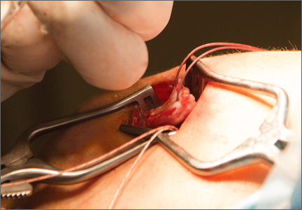
Two knotless suture anchors were compared: PushLock (4.5×18.5 mm; Arthrex) and ReelX STT (5.5×19.4 mm; Stryker). These anchors have multiple surgical indications (including RCR), allow patient-specific tissue tensioning, and use polyetheretherketone eyelets. The clamping force for PushLock depends entirely on the interference fit achieved for the suture between the outside of the anchor and the surrounding trabecular/cortical bone after device insertion, whereas the suture in ReelX is secured within the anchor shaft entirely by an internal ratchet-locking mechanism.
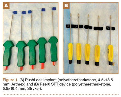
For anchor insertion, shoulders were dissected down to the greater tuberosity of the proximal humerus, and all implants were inserted (by a fellowship-trained surgeon in accordance with manufacturer guidelines) at a 25° insertion angle with manufacturer-supplied instruments. One anchor of each type (Figure 1) was inserted into the center of the rotator cuff footprint on the greater tuberosity of each specimen. Anterior and posterior positions were randomized, and an anchor from the other group was inserted into the matching location on the contralateral matched-pair specimen. In all instances, distance between the anterior and posterior anchors was 2 cm, and anchors were placed midway between the articular margin and the lateral edge of the greater tuberosity (Figure 2). Two strands of size 2 ultrahigh-molecular-weight–polyethylene Force Fiber (Stryker) were loaded into all anchors.
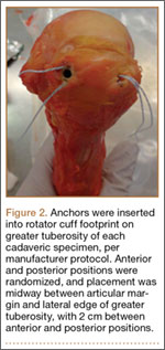
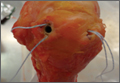
A custom urethane fixture was secured over the center of each anchor to allow testing to focus on suture slippage by minimizing anchor migration (Figure 3). The small aperture of this device allowed suture tails to pass freely through the center of the fixture but prevented disengagement and proximal migration of the suture anchor from the underlying bone through contact of the urethane fixture with the anchor perimeter. Any system deformation observed during testing was restricted to the suture and/or the anchor’s suture-locking mechanism. Testing fixtures also oriented the suture anchor coaxial with the axis of tension, creating a worst-case loading scenario (Figure 3).
PushLock implants were inserted with 5 pounds of tension, as indicated, using a manufacturer-supplied suture tensioner, and ReelX devices were inserted and locked with 2 full rotations, as specified by the manufacturer. After one end of each suture was cut, as would be done in vivo, the 2 other suture ends, which would have been part of the RCR in vivo, were tied together to form an 8-cm circumference loop that was brought through the urethane fixture. Humeri were then mounted in a materials testing system (MTS 810; MTS Systems) servohydraulic load frame, and the suture loop was passed around a cross-bar on the actuator of the testing device. A mechanical testing protocol consisting of modest repetitive forces was carefully chosen to simulate expected activity during rehabilitation after RCR.15 In this protocol, a 60-second preload of 10 N was followed by tensile loading between 10 N and 90 N at a frequency of 0.5 Hz for 500 cycles.15 Cycle duration at 3 mm and 5 mm of suture slippage (threshold for clinical failure) was recorded.12,16,17 In addition, suture slippage was measured after 1, 10, 50, 100, 200, 300, 400, and 500 cycles. The first 5 test cycles were not counted in the analysis to control for initial knot slippage. Finally, after completion of dynamic testing, samples were loaded at a displacement rate of 0.5 mm/s for tension-to-failure testing in the custom fixtures. Maximum failure load, stiffness, and failure mode were recorded. Ultimate failure was defined as suture breakage or gross suture slippage.
Paired Student t test was used to determine significant differences in suture slippage distance between the 2 groups at various cycle durations. In addition, Kaplan-Meier survival test was used to determine statistical differences in sample survival during the dynamic loading test.
Results
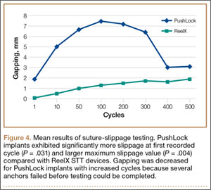
Mean (SD) BMD of the cadaveric shoulder specimens was 0.55 (0.13) g/cm2 (range, 0.29-0.68 g/cm2). The testing fixtures isolated suture slippage from anchor–bone disengagement. All 6 PushLock implants demonstrated slippage of more than 3 mm, and 5 of the 6 demonstrated slippage of more than 5 mm. All 6 ReelX devices exhibited slippage of less than 3 mm. In addition, PushLock demonstrated more suture slippage at cycles 1, 10, and 100 (P < .05) and more maximum slippage after 500 cycles (mean, 11.2 mm; SD, 4.7 mm) compared with ReelX (mean, 1.9 mm; SD, 0.5 mm) (P = .004). Figure 4 shows mean suture slippage at each cycle.
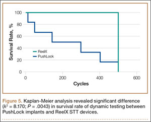
Kaplan-Meier analysis revealed significantly (λ2 = 8.170; P = .0043) decreased survival after dynamic testing for PushLock versus ReelX (Figure 5). Survival was defined as suture slippage of less than 5 mm after completion of dynamic testing. Only 1 of the 6 PushLock anchors completed dynamic testing; the other 5 failed via complete suture slippage from the anchor before testing could be completed. All 6 ReelX devices survived dynamic testing.
Therefore, 1 PushLock implant and all 6 ReelX devices were available for subsequent load-to-failure testing. Failure in this setting was defined as suture slippage of more than 10 mm or suture breakage. The PushLock implant failed at a maximum force of 171.8 N with a stiffness of 74.4 N/mm and eventually exhibited gross suture slippage. All 6 ReelX devices failed at a mean (SD) maximum of 273.5 (20.2) N, with a mean (SD) stiffness of 74.1 (17) N/mm. Mechanism of failure for all ReelX devices was suture breakage during the tensile load-to-failure test.
Discussion
We evaluated a new technique designed to isolate suture slippage in knotless anchors used for RCR. The impetus for developing this new method was to provide a means for better analyzing the ability of a knotless anchor to resist suture slippage in the cadaveric biomechanical testing setting. Suture slippage is an important mode of failure during such analyses.11,12 Significant slippage occurred in a range of implants before half the anchor–bone pullout strength was reached in a study using young bovine femoral heads.11 In another study, using young, high-BMD cadaveric humeral heads, initial slippage and maximum failure loads were equivalent among numerous devices using various suture-retention mechanisms, and suture slippage was the most common failure mode.12 Nevertheless, other biomechanical studies have demonstrated frequent failure caused by anchor pullout in elderly human cadaveric specimens with diminished BMD, often with high-force testing protocols.12,13 In the more modest-force, in vivo rehabilitative environment, suture slippage rather than anchor dislodgement may be the main failure mode.11-15
We compared the PushLock implant and its entirely press-fit suture clamping design with the ReelX device, which relies on an intrinsic suture-locking mechanism. Middle-aged (mean, 53.3 years; SD, 5.7 years) cadaveric humeri were tested under physiologically relevant biomechanical conditions to begin to help identify how relatively osteopenic bone may affect suture-retention properties for a given implant. The results showed that the study methodology prevented implant failure via anchor–bone pullout. To our knowledge, this was the first study to exclusively analyze suture slippage in knotless anchors. The findings indicated that implants that rely heavily on a tight interference fit of the suture between the anchor and the surrounding bone may exhibit early slippage and failure after RCR in middle-aged patients with relative osteopenia.11,12 However, this study also demonstrated that devices with intrinsic clamping mechanisms that do not depend on the quality of surrounding bone may better resist suture slippage. It is not clear that all knotless anchors with intrinsic locking mechanisms function equivalently. For instance, Pietschmann and colleagues12 found that 2 of 10 implants with a different internal clamping device were unable to resist failure via suture slippage, even in healthy bone. Similarly, in a study comparing ReelX devices with implants having a different internal suture-retention mechanism, ReelX failed at higher ultimate loads, and typically via anchor dislodgement, versus suture slippage in the other implants.18
It is important to note that, in the present study, the loads at which sutures broke in the intrinsic clamping anchors approached the maximum contractile force of the supraspinatus muscle (302 N).19,20 In addition, these loads were above the resistance of the rotator cuff tendon to cut out with modern suture material.21
This study’s limitations include use of an in vitro human cadaveric model that precluded analysis of the effects of postoperative healing. Biomechanical testing was also performed in a single row-type suture configuration with the rotator cuff tendon removed. Fixtures used during testing oriented the load coaxially with the axis of tension, creating a worst-case loading scenario. Although this form of testing may limit its clinical applicability, its purpose was to critically isolate how well a knotless anchor could resist suture slippage. The methods we used were also limited because the stability of the bone–anchor interface was not assessed. For patients with osteopenia, anchor pullout rather than suture slippage could be the most limiting factor for knotless anchor construct failure, and therefore further testing of both failure modes is needed. Future biomechanical studies should compare various knotless anchors’ suture-slippage characteristics in other constructs in physiologic testing orientations, including double-row and suture-bridge configurations, as well as with intact rotator cuff tendons. In addition, use of labral tape as a substitute for polyblend suture has been suggested to limit suture slippage, and this technique theoretically could have changed the results of this study.22
Conclusion
An implant with an internal ratcheting mechanism for suture retention demonstrated significantly less suture slippage in an axial tension evaluation protocol than a device reliant on interference fit of the suture between the anchor and surrounding bone. In the clinical setting, this may allow for less gap formation during the healing phase following RCR with a knotless anchor. There was also increased maximum load to failure, demonstrating an increased load until catastrophic failure using a device with a ratcheting internal locking mechanism.
1. Thal R. A knotless suture anchor. Design, function, and biomechanical testing. Am J Sports Med. 2001;29(5):646-649.
2. Cole BJ, ElAttrache NS, Anbari A. Arthroscopic rotator cuff repairs: an anatomic and biomechanical rationale for different suture-anchor repair configurations. Arthroscopy. 2007;23(6):662-669.
3. Kim KC, Shin HD, Cha SM, Lee WY. Comparison of repair integrity and functional outcomes for 3 arthroscopic suture bridge rotator cuff repair techniques. Am J Sports Med. 2013;41(2):271-277.
4. Choi CH, Kim SK, Cho MR, et al. Functional outcomes and structural integrity after double-pulley suture bridge rotator cuff repair using serial ultrasonographic examination. J Shoulder Elbow Surg. 2012;21(12):1753-1763.
5. Brown BS, Cooper AD, McIff TE, Key VH, Toby EB. Initial fixation and cyclic loading stability of knotless suture anchors for rotator cuff repair. J Shoulder Elbow Surg. 2008;17(2):313-318.
6. Burkhart SS, Adams CR, Burkhart SS, Schoolfield JD. A biomechanical comparison of 2 techniques of footprint reconstruction for rotator cuff repair: the SwiveLock-FiberChain construct versus standard double-row repair. Arthroscopy. 2009;25(3):274-281.
7. Hepp P, Osterhoff G, Engel T, Marquass B, Klink T, Josten C. Biomechanical evaluation of knotless anatomical double-layer double-row rotator cuff repair: a comparative ex vivo study. Am J Sports Med. 2009;37(7):1363-1369.
8. Maguire M, Goldberg J, Bokor D, et al. Biomechanical evaluation of four different transosseous-equivalent/suture bridge rotator cuff repairs. Knee Surg Sports Traumatol Arthrosc. 2011;19(9):1582-1587.
9. Millar NL, Wu X, Tantau R, Silverstone E, Murrell GA. Open versus two forms of arthroscopic rotator cuff repair. Clin Orthop Relat Res. 2009;467(4):966-978.
10. Rhee YG, Cho NS, Parke CS. Arthroscopic rotator cuff repair using modified Mason-Allen medial row stitch: knotless versus knot-tying suture bridge technique. Am J Sports Med. 2012;40(11):2440-2447.
11. Wieser K, Farshad M, Vlachopoulos L, Ruffieux K, Gerber C, Meyer DC. Suture slippage in knotless suture anchors as a potential failure mechanism in rotator cuff repair. Arthroscopy. 2012;28(11):1622-1627.
12. Pietschmann MF, Gülecyüz MF, Fieseler S, et al. Biomechanical stability of knotless suture anchors used in rotator cuff repair in healthy and osteopenic bone. Arthroscopy. 2010;26(8):1035-1044.
13. Barber FA, Hapa O, Bynum JA. Comparative testing by cyclic loading of rotator cuff suture anchors containing multiple high-strength sutures. Arthroscopy. 2010;26(9 suppl):S134-S141.
14. Barber FA, Coons DA, Ruiz-Suarez M. Cyclic load testing of biodegradable suture anchors containing 2 high-strength sutures. Arthroscopy. 2007;23(4):355-360.
15. Bynum CK, Lee S, Mahar A, Tasto J, Pedowitz R. Failure mode of suture anchors as a function of insertion depth. Am J Sports Med. 2005;33(7):1030-1034.
16. Gerber C, Schneeberger AG, Beck M, Schlegel U. Mechanical strength of repairs of the rotator cuff. J Bone Joint Surg Br. 1994;76(3):371-380.
17. Schneeberger AG, von Roll A, Kalberer F, Jacob HA, Gerber C. Mechanical strength of arthroscopic rotator cuff repair techniques: an in vitro study. J Bone Joint Surg Am. 2002;84(12):2152-2160.
18. Efird C, Traub S, Baldini T, et al. Knotless single-row rotator cuff repair: a comparative biomechanical study of 2 knotless suture anchors. Orthopedics. 2013;36(8):e1033-e1037.
19. Wright PB, Budoff JE, Yeh ML, Kelm ZS, Luo ZP. Strength of damaged suture: an in vitro study. Arthroscopy. 2006;22(12):1270-1275.
20. Burkhart SS. A stepwise approach to arthroscopic rotator cuff repair based on biomechanical principles. Arthroscopy. 2000;16(1):82-90.
21. Bisson LJ, Manohar LM. A biomechanical comparison of the pullout strength of No. 2 FiberWire suture and 2-mm FiberWire tape in bovine rotator cuff tendons. Arthroscopy. 2010;26(11):1463-1468.
22. Burkhart SS, Denard PJ, Konicek J, Hanypsiak BT. Biomechanical validation of load-sharing rip-stop fixation for the repair of tissue-deficient rotator cuff tears. Am J Sports Med. 2014;42(2):457-462.
Knotless suture anchor fixation techniques continue to evolve as efficient, low-profile options for arthroscopic rotator cuff repair (RCR).1,2 Excellent outcomes have been reported for constructs that use knotless fixation laterally, typically in suture bridge-type configurations.2-4 Early comparative biomechanical and clinical studies have also demonstrated equivalent results for all-knotless versus conventional constructs for arthroscopic RCR.5-10 Given the increased use and availability of multiple implant designs, it is important to supplement our clinical knowledge of these devices with laboratory studies delineating the biomechanical properties of the anchors that are used to help guide appropriate clinical use of the implants in specific patient populations.
Several biomechanical studies have shown suture slippage to be the weak but crucial link in the design of knotless anchors and the most likely mode of in vivo failure.11,12 Other studies have demonstrated frequent anchor dislodgement from bone, but these analyses involved use of elderly cadaveric specimens and relatively high-force testing protocols.12,13 Because suture-retention force may have exceeded anchor resistance to pullout (imparted by weak cadaveric bone in such biomechanical settings), the focus on suture-retention properties was limited.11 It is thought that, in clinical practice, the majority of patients who undergo RCR tend not to generate the high forces (relative to resistance to bone pullout) used to cause the anchor pullouts observed in biomechanical studies, particularly in the early postoperative setting.11-15 Cadaveric testing, however, often involves use of specimens with diminished bone mineral density (BMD), relative to age, because of the illness and other factors leading to death and donation.
Using a novel testing apparatus, we isolated, analyzed, and compared suture slippage in 2 anchor designs, one with entirely press-fit suture clamping and the other reliant on an intrinsic suture-locking mechanism.
Materials and Methods
Six human cadaveric proximal humeri specimens were used for this biomechanical study. Mean (SD) age was 53.3 (5.7) years (range, 46-59 years). Middle-aged specimens were used in order to best represent the quality of bone typically encountered in RCR surgery. To approximate tissue in clinical use, we used fresh-frozen cadaver tissue. Specimens were maintained at –20°C until about 24 hours before use and then were thawed to room temperature for testing. Specimens were included only if they had a completely intact humeral head and no prior surgery or hardware placement. Before instrumentation, dual-energy x-ray absorptiometry with a QDR-1000 scanner (Hologic) was used to determine BMD of all proximal humeri.
Two knotless suture anchors were compared: PushLock (4.5×18.5 mm; Arthrex) and ReelX STT (5.5×19.4 mm; Stryker). These anchors have multiple surgical indications (including RCR), allow patient-specific tissue tensioning, and use polyetheretherketone eyelets. The clamping force for PushLock depends entirely on the interference fit achieved for the suture between the outside of the anchor and the surrounding trabecular/cortical bone after device insertion, whereas the suture in ReelX is secured within the anchor shaft entirely by an internal ratchet-locking mechanism.
For anchor insertion, shoulders were dissected down to the greater tuberosity of the proximal humerus, and all implants were inserted (by a fellowship-trained surgeon in accordance with manufacturer guidelines) at a 25° insertion angle with manufacturer-supplied instruments. One anchor of each type (Figure 1) was inserted into the center of the rotator cuff footprint on the greater tuberosity of each specimen. Anterior and posterior positions were randomized, and an anchor from the other group was inserted into the matching location on the contralateral matched-pair specimen. In all instances, distance between the anterior and posterior anchors was 2 cm, and anchors were placed midway between the articular margin and the lateral edge of the greater tuberosity (Figure 2). Two strands of size 2 ultrahigh-molecular-weight–polyethylene Force Fiber (Stryker) were loaded into all anchors.
A custom urethane fixture was secured over the center of each anchor to allow testing to focus on suture slippage by minimizing anchor migration (Figure 3). The small aperture of this device allowed suture tails to pass freely through the center of the fixture but prevented disengagement and proximal migration of the suture anchor from the underlying bone through contact of the urethane fixture with the anchor perimeter. Any system deformation observed during testing was restricted to the suture and/or the anchor’s suture-locking mechanism. Testing fixtures also oriented the suture anchor coaxial with the axis of tension, creating a worst-case loading scenario (Figure 3).
PushLock implants were inserted with 5 pounds of tension, as indicated, using a manufacturer-supplied suture tensioner, and ReelX devices were inserted and locked with 2 full rotations, as specified by the manufacturer. After one end of each suture was cut, as would be done in vivo, the 2 other suture ends, which would have been part of the RCR in vivo, were tied together to form an 8-cm circumference loop that was brought through the urethane fixture. Humeri were then mounted in a materials testing system (MTS 810; MTS Systems) servohydraulic load frame, and the suture loop was passed around a cross-bar on the actuator of the testing device. A mechanical testing protocol consisting of modest repetitive forces was carefully chosen to simulate expected activity during rehabilitation after RCR.15 In this protocol, a 60-second preload of 10 N was followed by tensile loading between 10 N and 90 N at a frequency of 0.5 Hz for 500 cycles.15 Cycle duration at 3 mm and 5 mm of suture slippage (threshold for clinical failure) was recorded.12,16,17 In addition, suture slippage was measured after 1, 10, 50, 100, 200, 300, 400, and 500 cycles. The first 5 test cycles were not counted in the analysis to control for initial knot slippage. Finally, after completion of dynamic testing, samples were loaded at a displacement rate of 0.5 mm/s for tension-to-failure testing in the custom fixtures. Maximum failure load, stiffness, and failure mode were recorded. Ultimate failure was defined as suture breakage or gross suture slippage.
Paired Student t test was used to determine significant differences in suture slippage distance between the 2 groups at various cycle durations. In addition, Kaplan-Meier survival test was used to determine statistical differences in sample survival during the dynamic loading test.
Results
Mean (SD) BMD of the cadaveric shoulder specimens was 0.55 (0.13) g/cm2 (range, 0.29-0.68 g/cm2). The testing fixtures isolated suture slippage from anchor–bone disengagement. All 6 PushLock implants demonstrated slippage of more than 3 mm, and 5 of the 6 demonstrated slippage of more than 5 mm. All 6 ReelX devices exhibited slippage of less than 3 mm. In addition, PushLock demonstrated more suture slippage at cycles 1, 10, and 100 (P < .05) and more maximum slippage after 500 cycles (mean, 11.2 mm; SD, 4.7 mm) compared with ReelX (mean, 1.9 mm; SD, 0.5 mm) (P = .004). Figure 4 shows mean suture slippage at each cycle.
Kaplan-Meier analysis revealed significantly (λ2 = 8.170; P = .0043) decreased survival after dynamic testing for PushLock versus ReelX (Figure 5). Survival was defined as suture slippage of less than 5 mm after completion of dynamic testing. Only 1 of the 6 PushLock anchors completed dynamic testing; the other 5 failed via complete suture slippage from the anchor before testing could be completed. All 6 ReelX devices survived dynamic testing.
Therefore, 1 PushLock implant and all 6 ReelX devices were available for subsequent load-to-failure testing. Failure in this setting was defined as suture slippage of more than 10 mm or suture breakage. The PushLock implant failed at a maximum force of 171.8 N with a stiffness of 74.4 N/mm and eventually exhibited gross suture slippage. All 6 ReelX devices failed at a mean (SD) maximum of 273.5 (20.2) N, with a mean (SD) stiffness of 74.1 (17) N/mm. Mechanism of failure for all ReelX devices was suture breakage during the tensile load-to-failure test.
Discussion
We evaluated a new technique designed to isolate suture slippage in knotless anchors used for RCR. The impetus for developing this new method was to provide a means for better analyzing the ability of a knotless anchor to resist suture slippage in the cadaveric biomechanical testing setting. Suture slippage is an important mode of failure during such analyses.11,12 Significant slippage occurred in a range of implants before half the anchor–bone pullout strength was reached in a study using young bovine femoral heads.11 In another study, using young, high-BMD cadaveric humeral heads, initial slippage and maximum failure loads were equivalent among numerous devices using various suture-retention mechanisms, and suture slippage was the most common failure mode.12 Nevertheless, other biomechanical studies have demonstrated frequent failure caused by anchor pullout in elderly human cadaveric specimens with diminished BMD, often with high-force testing protocols.12,13 In the more modest-force, in vivo rehabilitative environment, suture slippage rather than anchor dislodgement may be the main failure mode.11-15
We compared the PushLock implant and its entirely press-fit suture clamping design with the ReelX device, which relies on an intrinsic suture-locking mechanism. Middle-aged (mean, 53.3 years; SD, 5.7 years) cadaveric humeri were tested under physiologically relevant biomechanical conditions to begin to help identify how relatively osteopenic bone may affect suture-retention properties for a given implant. The results showed that the study methodology prevented implant failure via anchor–bone pullout. To our knowledge, this was the first study to exclusively analyze suture slippage in knotless anchors. The findings indicated that implants that rely heavily on a tight interference fit of the suture between the anchor and the surrounding bone may exhibit early slippage and failure after RCR in middle-aged patients with relative osteopenia.11,12 However, this study also demonstrated that devices with intrinsic clamping mechanisms that do not depend on the quality of surrounding bone may better resist suture slippage. It is not clear that all knotless anchors with intrinsic locking mechanisms function equivalently. For instance, Pietschmann and colleagues12 found that 2 of 10 implants with a different internal clamping device were unable to resist failure via suture slippage, even in healthy bone. Similarly, in a study comparing ReelX devices with implants having a different internal suture-retention mechanism, ReelX failed at higher ultimate loads, and typically via anchor dislodgement, versus suture slippage in the other implants.18
It is important to note that, in the present study, the loads at which sutures broke in the intrinsic clamping anchors approached the maximum contractile force of the supraspinatus muscle (302 N).19,20 In addition, these loads were above the resistance of the rotator cuff tendon to cut out with modern suture material.21
This study’s limitations include use of an in vitro human cadaveric model that precluded analysis of the effects of postoperative healing. Biomechanical testing was also performed in a single row-type suture configuration with the rotator cuff tendon removed. Fixtures used during testing oriented the load coaxially with the axis of tension, creating a worst-case loading scenario. Although this form of testing may limit its clinical applicability, its purpose was to critically isolate how well a knotless anchor could resist suture slippage. The methods we used were also limited because the stability of the bone–anchor interface was not assessed. For patients with osteopenia, anchor pullout rather than suture slippage could be the most limiting factor for knotless anchor construct failure, and therefore further testing of both failure modes is needed. Future biomechanical studies should compare various knotless anchors’ suture-slippage characteristics in other constructs in physiologic testing orientations, including double-row and suture-bridge configurations, as well as with intact rotator cuff tendons. In addition, use of labral tape as a substitute for polyblend suture has been suggested to limit suture slippage, and this technique theoretically could have changed the results of this study.22
Conclusion
An implant with an internal ratcheting mechanism for suture retention demonstrated significantly less suture slippage in an axial tension evaluation protocol than a device reliant on interference fit of the suture between the anchor and surrounding bone. In the clinical setting, this may allow for less gap formation during the healing phase following RCR with a knotless anchor. There was also increased maximum load to failure, demonstrating an increased load until catastrophic failure using a device with a ratcheting internal locking mechanism.
1. Thal R. A knotless suture anchor. Design, function, and biomechanical testing. Am J Sports Med. 2001;29(5):646-649.
2. Cole BJ, ElAttrache NS, Anbari A. Arthroscopic rotator cuff repairs: an anatomic and biomechanical rationale for different suture-anchor repair configurations. Arthroscopy. 2007;23(6):662-669.
3. Kim KC, Shin HD, Cha SM, Lee WY. Comparison of repair integrity and functional outcomes for 3 arthroscopic suture bridge rotator cuff repair techniques. Am J Sports Med. 2013;41(2):271-277.
4. Choi CH, Kim SK, Cho MR, et al. Functional outcomes and structural integrity after double-pulley suture bridge rotator cuff repair using serial ultrasonographic examination. J Shoulder Elbow Surg. 2012;21(12):1753-1763.
5. Brown BS, Cooper AD, McIff TE, Key VH, Toby EB. Initial fixation and cyclic loading stability of knotless suture anchors for rotator cuff repair. J Shoulder Elbow Surg. 2008;17(2):313-318.
6. Burkhart SS, Adams CR, Burkhart SS, Schoolfield JD. A biomechanical comparison of 2 techniques of footprint reconstruction for rotator cuff repair: the SwiveLock-FiberChain construct versus standard double-row repair. Arthroscopy. 2009;25(3):274-281.
7. Hepp P, Osterhoff G, Engel T, Marquass B, Klink T, Josten C. Biomechanical evaluation of knotless anatomical double-layer double-row rotator cuff repair: a comparative ex vivo study. Am J Sports Med. 2009;37(7):1363-1369.
8. Maguire M, Goldberg J, Bokor D, et al. Biomechanical evaluation of four different transosseous-equivalent/suture bridge rotator cuff repairs. Knee Surg Sports Traumatol Arthrosc. 2011;19(9):1582-1587.
9. Millar NL, Wu X, Tantau R, Silverstone E, Murrell GA. Open versus two forms of arthroscopic rotator cuff repair. Clin Orthop Relat Res. 2009;467(4):966-978.
10. Rhee YG, Cho NS, Parke CS. Arthroscopic rotator cuff repair using modified Mason-Allen medial row stitch: knotless versus knot-tying suture bridge technique. Am J Sports Med. 2012;40(11):2440-2447.
11. Wieser K, Farshad M, Vlachopoulos L, Ruffieux K, Gerber C, Meyer DC. Suture slippage in knotless suture anchors as a potential failure mechanism in rotator cuff repair. Arthroscopy. 2012;28(11):1622-1627.
12. Pietschmann MF, Gülecyüz MF, Fieseler S, et al. Biomechanical stability of knotless suture anchors used in rotator cuff repair in healthy and osteopenic bone. Arthroscopy. 2010;26(8):1035-1044.
13. Barber FA, Hapa O, Bynum JA. Comparative testing by cyclic loading of rotator cuff suture anchors containing multiple high-strength sutures. Arthroscopy. 2010;26(9 suppl):S134-S141.
14. Barber FA, Coons DA, Ruiz-Suarez M. Cyclic load testing of biodegradable suture anchors containing 2 high-strength sutures. Arthroscopy. 2007;23(4):355-360.
15. Bynum CK, Lee S, Mahar A, Tasto J, Pedowitz R. Failure mode of suture anchors as a function of insertion depth. Am J Sports Med. 2005;33(7):1030-1034.
16. Gerber C, Schneeberger AG, Beck M, Schlegel U. Mechanical strength of repairs of the rotator cuff. J Bone Joint Surg Br. 1994;76(3):371-380.
17. Schneeberger AG, von Roll A, Kalberer F, Jacob HA, Gerber C. Mechanical strength of arthroscopic rotator cuff repair techniques: an in vitro study. J Bone Joint Surg Am. 2002;84(12):2152-2160.
18. Efird C, Traub S, Baldini T, et al. Knotless single-row rotator cuff repair: a comparative biomechanical study of 2 knotless suture anchors. Orthopedics. 2013;36(8):e1033-e1037.
19. Wright PB, Budoff JE, Yeh ML, Kelm ZS, Luo ZP. Strength of damaged suture: an in vitro study. Arthroscopy. 2006;22(12):1270-1275.
20. Burkhart SS. A stepwise approach to arthroscopic rotator cuff repair based on biomechanical principles. Arthroscopy. 2000;16(1):82-90.
21. Bisson LJ, Manohar LM. A biomechanical comparison of the pullout strength of No. 2 FiberWire suture and 2-mm FiberWire tape in bovine rotator cuff tendons. Arthroscopy. 2010;26(11):1463-1468.
22. Burkhart SS, Denard PJ, Konicek J, Hanypsiak BT. Biomechanical validation of load-sharing rip-stop fixation for the repair of tissue-deficient rotator cuff tears. Am J Sports Med. 2014;42(2):457-462.
Comparison of Outcomes and Costs of Tension-Band and Locking-Plate Osteosynthesis in Transverse Olecranon Fractures: A Matched-Cohort Study
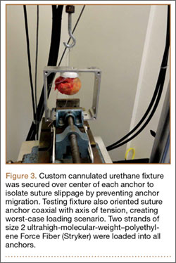
Olecranon fractures are a common injury, representing 10% of all upper extremity fractures.1 Displaced fractures require fixation to restore anatomical alignment and minimize posttraumatic arthrosis.2,3 Multiple surgical techniques have been developed to treat these fractures, with implant choice largely dictated by fracture pattern and associated injuries. Simple, noncomminuted, transverse, proximal fractures can be treated with a tension-band construct, and fractures that are comminuted, oblique, distal to the midpoint of the sigmoid notch, or associated with complex elbow injuries generally require locking-plate fixation.4,5 Although both tension bands and locking plates have been used successfully (Figures 1A, 1B), they remain some of the most frequently removed orthopedic implants, usually because of implant prominence.6

Both fixation devices have potential advantages and disadvantages. Tension-band fixation requires relatively “low-tech” instrumentation and implants and, as a result, has less cost and potentially less operative time for application. As it is smaller than a plate-and-screw construct, a tension band may be less prone to prominence, but this has not been substantiated in the literature.7-14 Implant migration has been a reported complication of tension-band fixation.7,11,13,15
Locking-plate fixation has been shown to be biomechanically stronger,16 and some reports have shown fewer repeat operations for implant prominence than with tension-band fixation.1,8,17-22 Because of more advanced product development and manufacturing, however, it comes at a higher cost. Plate fixation also requires more steps for application, which may require more operative time, and implant prominence has remained a problem, even with modern plates with lower profiles.19
Previous studies of olecranon fixation have included complex fractures and osteotomies or did not include current-generation precontoured locking plates. We found no other study that compared the outcomes, complications, and costs of tension-band and modern locking-plate fixation of isolated transverse olecranon fractures.
To determine if there are significant differences in outcomes and costs between tension-band and locking-plate fixation of transverse olecranon fractures in adults, we retrospectively compared functional outcomes, complications, and costs in 2 matched cohorts of displaced transverse olecranon fractures. We hypothesized that there would be no differences in functional outcomes, implant prominence, posttraumatic arthrosis, complications, or operative time, but that costs would be less with tension-band fixation.
Materials and Methods
After obtaining institutional review board approval, we retrospectively reviewed the medical records of patients who had undergone fixation of an isolated, transverse, noncomminuted olecranon fracture (Orthopaedic Trauma Association 21B1) at our institution between 2004 and 2011. Inclusion criteria included use of a tension-band construct or a precontoured locking plate, skeletal maturity at time of injury, and minimum 2-year follow-up. Exclusion criteria were open fractures, osteotomies, any other ipsilateral upper extremity fracture, and fractures with comminution, obliquity, or distal location.
Although, based on fracture pattern, tension-band fixation is appropriate for olecranon osteotomies used for distal humeral exposure, we did not include osteotomies because functional outcomes would likely be different from those of true olecranon fractures, in addition to the possibility that the soft-tissue injury from a distal humeral fracture and resultant exposure could result in a different level of implant prominence. To control for demographic variables, we used a cohort design in which patients were matched on age and length of follow-up.
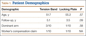
During the study period, we treated 287 olecranon fractures. Forty-nine patients met the inclusion criteria. The study population consisted of 20 patients, 10 in each cohort matched on age and length of follow-up. There were no statistically significant differences between groups in demographic variables, including dominant arm involved and number of worker’s compensation claims (Table 1). Mechanisms of injury were similar in the groups. In the tension-band group, 9 patients fell directly onto their elbow, and 1 fell onto her outstretched hand. In the locking-plate group, 8 patients fell directly onto the elbow, 1 fell onto her outstretched hand, and 1 was injured in a motorcycle accident.
All surgeons, regardless of implant selected, used a posterior incision that curved slightly laterally about the tip of the olecranon. Surgeon preference determined which fixation construct to use. Tension-band fixation was performed using 2 bicortical Kirschner wires and a stainless-steel wire through a distal drill hole to complete the tension band. Of the 10 locking-plate constructs used, 4 were PERI-LOC olecranon locking plates (Smith & Nephew), 3 were LCP olecranon plates (Synthes), and 3 were periarticular proximal ulna locking plates (Zimmer).
All returning patients were seen by either Dr. Amini or Mr. Wilson and underwent range of motion (ROM) measurement with a goniometer; assessment for subjective and objective implant prominence (graded none, mild, moderate, or severe/already had implant removed); and functional scoring using the Mayo Elbow Performance Score (MEPS) and the Quick Disability of the Arm, Shoulder, and Hand (QDASH). Results were classified excellent (MEPS, >90), good (75-89), fair (60-74), and poor (<60).23
Anteroposterior and lateral radiographs of the elbow were obtained at follow-up and were examined for maintenance/integrity of implants, radiographic union, and posttraumatic arthrosis. Arthrosis was graded using the Broberg and Morrey24 classification: grade 0 (normal elbow), grade 1 (slight joint-space narrowing with minimal osteophyte formation), grade 2 (moderate joint-space narrowing with moderate osteophyte formation), grade 3 (severe degenerative changes with gross destruction of joint).
Medical records were examined to determine surgery time. Billing information was examined to determine charges related to each operation, specifically the charge for the implants and the overall charge for the operation, which included anesthesia charges. Subsequent operations were included as applicable.
Student t test was used to compare differences in normative data, and Pearson χ2 test to compare differences in categorical data. Differences with P < .05 were considered significant.
Results
There were no clinically or statistically significant differences in ROM or functional outcomes (Table 2). According to MEPS, results were excellent in 8 and good in 2 patients in the tension-band group and excellent in 7 and good in 3 patients in the locking-plate group.
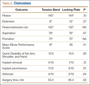
In patients who had implants removed, average time to subsequent procedure was 6.2 months, and all patients who underwent implant removal did so before 1-year follow-up. Implant removal was required in 4 tension-band patients and 1 locking-plate patient (P = .12). Similarly, 7 tension-band patients (including those with implants removed) and 3 locking-plate patients had implant-related symptoms, with the difference trending (P = .07) toward significance (Table 2).
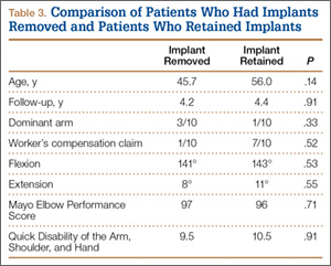
Patients who elected to have their implants removed tended to be younger than those who did not (45.7 vs 56.0 years); the difference (P = .14) was not significant. Worker’s compensation status did not affect the decision to undergo implant removal. At final follow-up, there were no differences in ROM or functional outcomes between patients who had implants removed and those who did not. No variable predicted which patients had implants removed or not (Table 3).
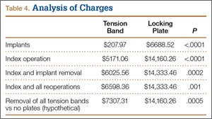
Implant charges were $207.97 for the tension-band cohort and $6688.52 for the locking-plate cohort (P < .0001). Operative charges for the index procedures were $5171.06 for tension-band fixation and $14,160.26 for locking-plate fixation (P < .0001). Overall operative charges, including charges for subsequent operations, were $6598.36 in the tension-band cohort and $14,333.46 in the locking-plate cohort (P = .001). In a comparison of combined charges for index procedure and implant removal (excluding other repeat operations), charges were $6025.56 for the tension-band cohort and $14,333.46 for the locking-plate cohort (P = .0002). Even if all patients with tension-band fixation and no patients with locking-plate fixation had implant removal, mean charges for all operative care would still be significantly (P = .0005) less in the tension-band cohort than in the locking-plate cohort ($7307.31 vs $14,160.26) (Table 4).
Surgery time was significantly (P = .025) less for tension-band fixation than for locking-plate fixation (55.3 vs 85.4 minutes) (Table 2).
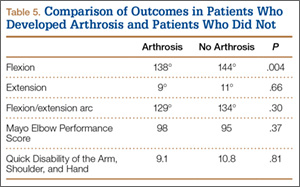
Four tension-band patients and 3 locking-plate patients had radiographic evidence of grade 1 posttraumatic arthrosis (P = .64). None required subsequent procedures. Patients with posttraumatic arthrosis had slightly less flexion, but there was no difference in overall flexion-extension arc or functional outcomes between patients with and without arthrosis (Table 5).
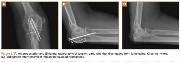
The locking-plate cohort had no other complications, and the tension-band cohort had 3. In 1 tension-band patient, the wire disengaged from the Kirschner wires. The fracture healed, but a subsequent procedure was required for symptomatic implant prominence (Figures 2A–2C). Another tension-band patient developed both posttraumatic arthrofibrosis and cubital tunnel syndrome, in addition to a prominent implant. She underwent capsular release, ulnar nerve transposition, and implant removal. At final follow-up, motion was improved, and ulnar nerve symptoms were resolved. There were no infections in either group. Overall, there were no statistically significant differences in complications between groups.
Discussion
We conducted this study to determine differences between tension-band and locking-plate fixation of isolated, closed, noncomminuted, transverse olecranon fractures. Few studies have directly compared tension-band and locking-plate fixation,8,10,19,25 particularly in reference to outcomes of functional scores, implant prominence, complications, operative time, and cost-effectiveness. We found no study that clinically compared these implants since the advent of precontoured locking plates, and no study that compared results in similar fracture patterns. In our study, we found no differences in functional or radiographic outcomes between groups, but significant differences in charges and overall cost of care.
Our findings suggest that patients return to high functional level an average of 4.3 years after fixation of an olecranon fracture with either a tension band or a locking plate. Both cohorts achieved QDASH scores equivalent to normative values for the general population,26 and all patients in both cohorts achieved either good or excellent results based on MEPS values.23 This is comparable to reported functional outcomes in the literature, with previous reports suggesting 86% to 92% of patients obtain good or excellent results.1,7,8,12,14,17,18,27 The rate of posttraumatic arthrosis in both cohorts was low, and, when present, arthrosis was radiographically mild (no patient had grade 2 or 3 arthrosis). Patients with and without radiographic evidence of arthrosis had similar ROM and functional outcomes.
Our findings also suggest a trend toward fewer implant-related symptoms and less need for implant removal in patients treated with locking plates. Although both implants have high rates of prominence requiring removal, most studies support our findings that tension bands are more prominent than locking plates. Fixation has been reported to cause prominence requiring removal in 42% to 82% of patients with tension bands7-14 and 0% to 47% of patients with locking plates.1,8,17,18,20-22,28 It is important to note that many earlier studies either were conducted before the advent of precontoured locking plates or were not comparative.1,7,9-14,17,18,20-22,28 In one recent study, however, Edwards and colleagues19 surveyed 138 patients and found very similar implant removal rates: 63.6% for tension bands and 62.5% for locking plates. Nevertheless, implant removal rates for fixation of olecranon fractures remain high, regardless of implant used.
Our data did not reveal any difference in ROM or functional outcomes between patients who had and did not have implants removed. This suggests, first, that QDASH and MEPS may not be sensitive in identifying patients with implant prominence, as neither questionnaire incorporates implant prominence into its scoring, and, second, that implant removal does not significantly impair ROM. As a result, surgeons should consider asking patients specifically about symptoms of prominent implants once there is convincing evidence of union and counseling them about implant removal if appropriate.
To our knowledge, the differences in cost and operative time between tension-band and locking-plate fixation have not been previously reported. Our data suggest that the financial differences resulted mainly from implant charges; overall, tension-band fixation was roughly half the cost of locking-plate fixation. In addition, in patients who eventually had implants removed, the cost of implant removal was relatively small compared with the cost of the initial fixation in both cohorts. As a result, even if all patients in the tension-band cohort and no patients in the locking-plate cohort had implants removed, tension-band fixation and subsequent implant removal would still cost half as much as locking-plate fixation without implant removal. Moreover, fixation with a tension band took roughly 30 minutes less than fixation with a plate. Less time in the operating room likely contributed to the additional cost savings realized with tension-band fixation beyond those directly resulting from implant cost.
The strength of this study lies in the homogeneity of cohorts. Each cohort was matched primarily on age and secondarily on length of follow-up. All patients had closed, proximal, transverse fractures without comminution, and we excluded olecranon osteotomies as these represent an entity different from true fractures. Fractures with comminution or distal extension may represent more severe injuries, and functional scores, complications, hardware prominence, and operative time might have been affected by inclusion of these fractures. Further, there were no infections in either group to skew the rate of implant prominence or removal.
The weaknesses of the study lie in its limited sample sizes, retrospective design, and lack of long-term follow-up. Group size was limited by our attempts to create homogenous cohorts. As a result, some patients were not included as participants because of strict exclusion criteria. Most notably, we excluded any fracture not appropriate for tension-band fixation, as well as open fractures and osteotomies. Despite the retrospective nature of the study, all patients were examined by the investigators at final follow-up (minimum, 2 years) for the purpose of this study. It is possible that these functional results may not be sustained over the long term, as the risk for posttraumatic arthrosis in articular injuries builds with time. Although some patients may want to have implants removed later, all our study patients who had implants removed had them removed within 1 year, and all 20 patients were reached at minimum 2-year follow-up. Thus, it is unlikely but possible that some of the other study patients will elect to have implants removed.
1. Buijze G, Kloen P. Clinical evaluation of locking compression plate fixation for comminuted olecranon fractures. J Bone Joint Surg Am. 2009;91(10):
2416-2420.
2. Newman SD, Mauffrey C, Krikler S. Olecranon fractures. Injury. 2009;40(6):575-581.
3. Veillette CJ, Steinmann SP. Olecranon fractures. Orthop Clin North Am. 2008;39(2):229-236.
4. Baecher N, Edwards S. Olecranon fractures. J Hand Surg Am. 2013;38(3):593-604.
5. Hak DJ, Golladay GJ. Olecranon fractures: treatment options. J Am Acad Orthop Surg. 2000;8(4):266-275.
6. Busam ML, Esther RJ, Obremskey WT. Hardware removal: indications and expectations. J Am Acad Orthop Surg. 2006;14(2):113-120.
7. Chalidis BE, Sachinis NC, Samoladas EP, Dimitriou CG, Pournaras JD. Is tension band wiring technique the “gold standard” for the treatment of olecranon fractures? A long term functional outcome study. J Orthop Surg Res. 2008;3:9.
8. Hume MC, Wiss DA. Olecranon fractures: a clinical and radiographic comparison of tension-band wiring and plate fixation. Clin Orthop Relat Res. 1992;(285):229-235.
9. Karlsson MK, Hasserius R, Besjakov J, Karlsson C, Josefsson PO. Comparison of tension-band and figure-of-eight wiring techniques for treatment of olecranon fractures. J Shoulder Elbow Surg. 2002;11(4):377-382.
10. Lindenhovius AL, Brouwer KM, Doornberg JN, Ring DC, Kloen P. Long-term outcome of operatively treated fracture-dislocations of the olecranon. J Orthop Trauma. 2008;22(5):325-331.
11. Macko D, Szabo RM. Complications of tension-band wiring of olecranon fractures. J Bone Joint Surg Am. 1985;67(9):1396-1401.
12. Romero JM, Miran A, Jensen CH. Complications and re-operation rate after tension-band wiring of olecranon fractures. J Orthop Sci. 2000;5(4):318-320.
13. Rommens PM, Schneider RU, Reuter M. Functional results after operative treatment of olecranon fractures. Acta Chir Belg. 2004;104(2):191-197.
14. Villanueva P, Osorio F, Commessatti M, Sanchez-Sotelo J. Tension-band wiring for olecranon fractures: analysis of risk factors for failure. J Shoulder Elbow Surg. 2006;15(3):351-356.
15. Sahajpal D, Wright TW. Proximal ulna fractures. J Hand Surg Am. 2009;34(2):357-362.
16. Rouleau DM, Sandman E, van Riet R, Galatz LM. Management of fractures of the proximal ulna. J Am Acad Orthop Surg. 2013;21(3):149-160.
17. Anderson ML, Larson AN, Merten SM, Steinmann SP. Congruent elbow plate fixation of olecranon fractures. J Orthop Trauma. 2007;21(6):386-393.
18. Bailey CS, MacDermid J, Patterson SD, King GJ. Outcome of plate fixation of olecranon fractures. J Orthop Trauma. 2001;15(8):542-548.
19. Edwards SG, Cohen MS, Lattanza LL, et al. Surgeon perceptions and patient outcomes regarding proximal ulna fixation: a multicenter experience. J Shoulder Elbow Surg. 2012;21(12):1637-1643.
20. Munoz-Mahamud E, Fernandez-Valencia JA, Riba J. Plate osteosynthesis for severe olecranon fractures. J Orthop Surg. 2010;18(1):80-84.
21. Simpson NS, Goodman LA, Jupiter JB. Contoured LCDC plating of the proximal ulna. Injury. 1996;27(6):411-417.
22. Tejwani NC, Garnham IR, Wolinsky PR, Kummer FJ, Koval KJ. Posterior olecranon plating: biomechanical and clinical evaluation of a new operative technique. Bull Hosp Jt Dis. 2002-2003;61(1-2):27-31.
23. Morrey BF, An KN. Functional evaluation of the elbow. In: Morrey BF, Sanchez-Sotelo J, eds. The Elbow and Its Disorders. 4th ed. Philadelphia, PA: Elsevier; 2008:87-88.
24. Broberg MA, Morrey BF. The results of delayed excision of the radial head for fracture. J Bone Joint Surg Am. 1986;68(5):669-674.
25. Horne JG, Tanzer TL. Olecranon fractures: a review of 100 cases. J Trauma. 1981;21(6):469-472.
26. Hunsaker FG, Cioffi DA, Amadio PC, Wright JG, Caughlin B. The American Academy of Orthopaedic Surgeons outcomes instruments: normative values from the general population. J Bone Joint Surg Am. 2002;84(2):208-215.
27. Ikeda M, Fukushima Y, Kobayashi Y, Oka Y. Comminuted fractures of the olecranon. Management by bone graft from the iliac crest and multiple tension-band wiring. J Bone Joint Surg Br. 2001;83(6):805-808.
28. Erturer RE, Sever C, Sonmez MM, Ozcelik IB, Akman S, Ozturk I. Results of open reduction and plate osteosynthesis in comminuted fracture of the olecranon. J Shoulder Elbow Surg. 2011;20(3):449-454.
Olecranon fractures are a common injury, representing 10% of all upper extremity fractures.1 Displaced fractures require fixation to restore anatomical alignment and minimize posttraumatic arthrosis.2,3 Multiple surgical techniques have been developed to treat these fractures, with implant choice largely dictated by fracture pattern and associated injuries. Simple, noncomminuted, transverse, proximal fractures can be treated with a tension-band construct, and fractures that are comminuted, oblique, distal to the midpoint of the sigmoid notch, or associated with complex elbow injuries generally require locking-plate fixation.4,5 Although both tension bands and locking plates have been used successfully (Figures 1A, 1B), they remain some of the most frequently removed orthopedic implants, usually because of implant prominence.6
Both fixation devices have potential advantages and disadvantages. Tension-band fixation requires relatively “low-tech” instrumentation and implants and, as a result, has less cost and potentially less operative time for application. As it is smaller than a plate-and-screw construct, a tension band may be less prone to prominence, but this has not been substantiated in the literature.7-14 Implant migration has been a reported complication of tension-band fixation.7,11,13,15
Locking-plate fixation has been shown to be biomechanically stronger,16 and some reports have shown fewer repeat operations for implant prominence than with tension-band fixation.1,8,17-22 Because of more advanced product development and manufacturing, however, it comes at a higher cost. Plate fixation also requires more steps for application, which may require more operative time, and implant prominence has remained a problem, even with modern plates with lower profiles.19
Previous studies of olecranon fixation have included complex fractures and osteotomies or did not include current-generation precontoured locking plates. We found no other study that compared the outcomes, complications, and costs of tension-band and modern locking-plate fixation of isolated transverse olecranon fractures.
To determine if there are significant differences in outcomes and costs between tension-band and locking-plate fixation of transverse olecranon fractures in adults, we retrospectively compared functional outcomes, complications, and costs in 2 matched cohorts of displaced transverse olecranon fractures. We hypothesized that there would be no differences in functional outcomes, implant prominence, posttraumatic arthrosis, complications, or operative time, but that costs would be less with tension-band fixation.
Materials and Methods
After obtaining institutional review board approval, we retrospectively reviewed the medical records of patients who had undergone fixation of an isolated, transverse, noncomminuted olecranon fracture (Orthopaedic Trauma Association 21B1) at our institution between 2004 and 2011. Inclusion criteria included use of a tension-band construct or a precontoured locking plate, skeletal maturity at time of injury, and minimum 2-year follow-up. Exclusion criteria were open fractures, osteotomies, any other ipsilateral upper extremity fracture, and fractures with comminution, obliquity, or distal location.
Although, based on fracture pattern, tension-band fixation is appropriate for olecranon osteotomies used for distal humeral exposure, we did not include osteotomies because functional outcomes would likely be different from those of true olecranon fractures, in addition to the possibility that the soft-tissue injury from a distal humeral fracture and resultant exposure could result in a different level of implant prominence. To control for demographic variables, we used a cohort design in which patients were matched on age and length of follow-up.
During the study period, we treated 287 olecranon fractures. Forty-nine patients met the inclusion criteria. The study population consisted of 20 patients, 10 in each cohort matched on age and length of follow-up. There were no statistically significant differences between groups in demographic variables, including dominant arm involved and number of worker’s compensation claims (Table 1). Mechanisms of injury were similar in the groups. In the tension-band group, 9 patients fell directly onto their elbow, and 1 fell onto her outstretched hand. In the locking-plate group, 8 patients fell directly onto the elbow, 1 fell onto her outstretched hand, and 1 was injured in a motorcycle accident.
All surgeons, regardless of implant selected, used a posterior incision that curved slightly laterally about the tip of the olecranon. Surgeon preference determined which fixation construct to use. Tension-band fixation was performed using 2 bicortical Kirschner wires and a stainless-steel wire through a distal drill hole to complete the tension band. Of the 10 locking-plate constructs used, 4 were PERI-LOC olecranon locking plates (Smith & Nephew), 3 were LCP olecranon plates (Synthes), and 3 were periarticular proximal ulna locking plates (Zimmer).
All returning patients were seen by either Dr. Amini or Mr. Wilson and underwent range of motion (ROM) measurement with a goniometer; assessment for subjective and objective implant prominence (graded none, mild, moderate, or severe/already had implant removed); and functional scoring using the Mayo Elbow Performance Score (MEPS) and the Quick Disability of the Arm, Shoulder, and Hand (QDASH). Results were classified excellent (MEPS, >90), good (75-89), fair (60-74), and poor (<60).23
Anteroposterior and lateral radiographs of the elbow were obtained at follow-up and were examined for maintenance/integrity of implants, radiographic union, and posttraumatic arthrosis. Arthrosis was graded using the Broberg and Morrey24 classification: grade 0 (normal elbow), grade 1 (slight joint-space narrowing with minimal osteophyte formation), grade 2 (moderate joint-space narrowing with moderate osteophyte formation), grade 3 (severe degenerative changes with gross destruction of joint).
Medical records were examined to determine surgery time. Billing information was examined to determine charges related to each operation, specifically the charge for the implants and the overall charge for the operation, which included anesthesia charges. Subsequent operations were included as applicable.
Student t test was used to compare differences in normative data, and Pearson χ2 test to compare differences in categorical data. Differences with P < .05 were considered significant.
Results
There were no clinically or statistically significant differences in ROM or functional outcomes (Table 2). According to MEPS, results were excellent in 8 and good in 2 patients in the tension-band group and excellent in 7 and good in 3 patients in the locking-plate group.
In patients who had implants removed, average time to subsequent procedure was 6.2 months, and all patients who underwent implant removal did so before 1-year follow-up. Implant removal was required in 4 tension-band patients and 1 locking-plate patient (P = .12). Similarly, 7 tension-band patients (including those with implants removed) and 3 locking-plate patients had implant-related symptoms, with the difference trending (P = .07) toward significance (Table 2).
Patients who elected to have their implants removed tended to be younger than those who did not (45.7 vs 56.0 years); the difference (P = .14) was not significant. Worker’s compensation status did not affect the decision to undergo implant removal. At final follow-up, there were no differences in ROM or functional outcomes between patients who had implants removed and those who did not. No variable predicted which patients had implants removed or not (Table 3).
Implant charges were $207.97 for the tension-band cohort and $6688.52 for the locking-plate cohort (P < .0001). Operative charges for the index procedures were $5171.06 for tension-band fixation and $14,160.26 for locking-plate fixation (P < .0001). Overall operative charges, including charges for subsequent operations, were $6598.36 in the tension-band cohort and $14,333.46 in the locking-plate cohort (P = .001). In a comparison of combined charges for index procedure and implant removal (excluding other repeat operations), charges were $6025.56 for the tension-band cohort and $14,333.46 for the locking-plate cohort (P = .0002). Even if all patients with tension-band fixation and no patients with locking-plate fixation had implant removal, mean charges for all operative care would still be significantly (P = .0005) less in the tension-band cohort than in the locking-plate cohort ($7307.31 vs $14,160.26) (Table 4).
Surgery time was significantly (P = .025) less for tension-band fixation than for locking-plate fixation (55.3 vs 85.4 minutes) (Table 2).
Four tension-band patients and 3 locking-plate patients had radiographic evidence of grade 1 posttraumatic arthrosis (P = .64). None required subsequent procedures. Patients with posttraumatic arthrosis had slightly less flexion, but there was no difference in overall flexion-extension arc or functional outcomes between patients with and without arthrosis (Table 5).
The locking-plate cohort had no other complications, and the tension-band cohort had 3. In 1 tension-band patient, the wire disengaged from the Kirschner wires. The fracture healed, but a subsequent procedure was required for symptomatic implant prominence (Figures 2A–2C). Another tension-band patient developed both posttraumatic arthrofibrosis and cubital tunnel syndrome, in addition to a prominent implant. She underwent capsular release, ulnar nerve transposition, and implant removal. At final follow-up, motion was improved, and ulnar nerve symptoms were resolved. There were no infections in either group. Overall, there were no statistically significant differences in complications between groups.
Discussion
We conducted this study to determine differences between tension-band and locking-plate fixation of isolated, closed, noncomminuted, transverse olecranon fractures. Few studies have directly compared tension-band and locking-plate fixation,8,10,19,25 particularly in reference to outcomes of functional scores, implant prominence, complications, operative time, and cost-effectiveness. We found no study that clinically compared these implants since the advent of precontoured locking plates, and no study that compared results in similar fracture patterns. In our study, we found no differences in functional or radiographic outcomes between groups, but significant differences in charges and overall cost of care.
Our findings suggest that patients return to high functional level an average of 4.3 years after fixation of an olecranon fracture with either a tension band or a locking plate. Both cohorts achieved QDASH scores equivalent to normative values for the general population,26 and all patients in both cohorts achieved either good or excellent results based on MEPS values.23 This is comparable to reported functional outcomes in the literature, with previous reports suggesting 86% to 92% of patients obtain good or excellent results.1,7,8,12,14,17,18,27 The rate of posttraumatic arthrosis in both cohorts was low, and, when present, arthrosis was radiographically mild (no patient had grade 2 or 3 arthrosis). Patients with and without radiographic evidence of arthrosis had similar ROM and functional outcomes.
Our findings also suggest a trend toward fewer implant-related symptoms and less need for implant removal in patients treated with locking plates. Although both implants have high rates of prominence requiring removal, most studies support our findings that tension bands are more prominent than locking plates. Fixation has been reported to cause prominence requiring removal in 42% to 82% of patients with tension bands7-14 and 0% to 47% of patients with locking plates.1,8,17,18,20-22,28 It is important to note that many earlier studies either were conducted before the advent of precontoured locking plates or were not comparative.1,7,9-14,17,18,20-22,28 In one recent study, however, Edwards and colleagues19 surveyed 138 patients and found very similar implant removal rates: 63.6% for tension bands and 62.5% for locking plates. Nevertheless, implant removal rates for fixation of olecranon fractures remain high, regardless of implant used.
Our data did not reveal any difference in ROM or functional outcomes between patients who had and did not have implants removed. This suggests, first, that QDASH and MEPS may not be sensitive in identifying patients with implant prominence, as neither questionnaire incorporates implant prominence into its scoring, and, second, that implant removal does not significantly impair ROM. As a result, surgeons should consider asking patients specifically about symptoms of prominent implants once there is convincing evidence of union and counseling them about implant removal if appropriate.
To our knowledge, the differences in cost and operative time between tension-band and locking-plate fixation have not been previously reported. Our data suggest that the financial differences resulted mainly from implant charges; overall, tension-band fixation was roughly half the cost of locking-plate fixation. In addition, in patients who eventually had implants removed, the cost of implant removal was relatively small compared with the cost of the initial fixation in both cohorts. As a result, even if all patients in the tension-band cohort and no patients in the locking-plate cohort had implants removed, tension-band fixation and subsequent implant removal would still cost half as much as locking-plate fixation without implant removal. Moreover, fixation with a tension band took roughly 30 minutes less than fixation with a plate. Less time in the operating room likely contributed to the additional cost savings realized with tension-band fixation beyond those directly resulting from implant cost.
The strength of this study lies in the homogeneity of cohorts. Each cohort was matched primarily on age and secondarily on length of follow-up. All patients had closed, proximal, transverse fractures without comminution, and we excluded olecranon osteotomies as these represent an entity different from true fractures. Fractures with comminution or distal extension may represent more severe injuries, and functional scores, complications, hardware prominence, and operative time might have been affected by inclusion of these fractures. Further, there were no infections in either group to skew the rate of implant prominence or removal.
The weaknesses of the study lie in its limited sample sizes, retrospective design, and lack of long-term follow-up. Group size was limited by our attempts to create homogenous cohorts. As a result, some patients were not included as participants because of strict exclusion criteria. Most notably, we excluded any fracture not appropriate for tension-band fixation, as well as open fractures and osteotomies. Despite the retrospective nature of the study, all patients were examined by the investigators at final follow-up (minimum, 2 years) for the purpose of this study. It is possible that these functional results may not be sustained over the long term, as the risk for posttraumatic arthrosis in articular injuries builds with time. Although some patients may want to have implants removed later, all our study patients who had implants removed had them removed within 1 year, and all 20 patients were reached at minimum 2-year follow-up. Thus, it is unlikely but possible that some of the other study patients will elect to have implants removed.
1. Buijze G, Kloen P. Clinical evaluation of locking compression plate fixation for comminuted olecranon fractures. J Bone Joint Surg Am. 2009;91(10):
2416-2420.
2. Newman SD, Mauffrey C, Krikler S. Olecranon fractures. Injury. 2009;40(6):575-581.
3. Veillette CJ, Steinmann SP. Olecranon fractures. Orthop Clin North Am. 2008;39(2):229-236.
4. Baecher N, Edwards S. Olecranon fractures. J Hand Surg Am. 2013;38(3):593-604.
5. Hak DJ, Golladay GJ. Olecranon fractures: treatment options. J Am Acad Orthop Surg. 2000;8(4):266-275.
6. Busam ML, Esther RJ, Obremskey WT. Hardware removal: indications and expectations. J Am Acad Orthop Surg. 2006;14(2):113-120.
7. Chalidis BE, Sachinis NC, Samoladas EP, Dimitriou CG, Pournaras JD. Is tension band wiring technique the “gold standard” for the treatment of olecranon fractures? A long term functional outcome study. J Orthop Surg Res. 2008;3:9.
8. Hume MC, Wiss DA. Olecranon fractures: a clinical and radiographic comparison of tension-band wiring and plate fixation. Clin Orthop Relat Res. 1992;(285):229-235.
9. Karlsson MK, Hasserius R, Besjakov J, Karlsson C, Josefsson PO. Comparison of tension-band and figure-of-eight wiring techniques for treatment of olecranon fractures. J Shoulder Elbow Surg. 2002;11(4):377-382.
10. Lindenhovius AL, Brouwer KM, Doornberg JN, Ring DC, Kloen P. Long-term outcome of operatively treated fracture-dislocations of the olecranon. J Orthop Trauma. 2008;22(5):325-331.
11. Macko D, Szabo RM. Complications of tension-band wiring of olecranon fractures. J Bone Joint Surg Am. 1985;67(9):1396-1401.
12. Romero JM, Miran A, Jensen CH. Complications and re-operation rate after tension-band wiring of olecranon fractures. J Orthop Sci. 2000;5(4):318-320.
13. Rommens PM, Schneider RU, Reuter M. Functional results after operative treatment of olecranon fractures. Acta Chir Belg. 2004;104(2):191-197.
14. Villanueva P, Osorio F, Commessatti M, Sanchez-Sotelo J. Tension-band wiring for olecranon fractures: analysis of risk factors for failure. J Shoulder Elbow Surg. 2006;15(3):351-356.
15. Sahajpal D, Wright TW. Proximal ulna fractures. J Hand Surg Am. 2009;34(2):357-362.
16. Rouleau DM, Sandman E, van Riet R, Galatz LM. Management of fractures of the proximal ulna. J Am Acad Orthop Surg. 2013;21(3):149-160.
17. Anderson ML, Larson AN, Merten SM, Steinmann SP. Congruent elbow plate fixation of olecranon fractures. J Orthop Trauma. 2007;21(6):386-393.
18. Bailey CS, MacDermid J, Patterson SD, King GJ. Outcome of plate fixation of olecranon fractures. J Orthop Trauma. 2001;15(8):542-548.
19. Edwards SG, Cohen MS, Lattanza LL, et al. Surgeon perceptions and patient outcomes regarding proximal ulna fixation: a multicenter experience. J Shoulder Elbow Surg. 2012;21(12):1637-1643.
20. Munoz-Mahamud E, Fernandez-Valencia JA, Riba J. Plate osteosynthesis for severe olecranon fractures. J Orthop Surg. 2010;18(1):80-84.
21. Simpson NS, Goodman LA, Jupiter JB. Contoured LCDC plating of the proximal ulna. Injury. 1996;27(6):411-417.
22. Tejwani NC, Garnham IR, Wolinsky PR, Kummer FJ, Koval KJ. Posterior olecranon plating: biomechanical and clinical evaluation of a new operative technique. Bull Hosp Jt Dis. 2002-2003;61(1-2):27-31.
23. Morrey BF, An KN. Functional evaluation of the elbow. In: Morrey BF, Sanchez-Sotelo J, eds. The Elbow and Its Disorders. 4th ed. Philadelphia, PA: Elsevier; 2008:87-88.
24. Broberg MA, Morrey BF. The results of delayed excision of the radial head for fracture. J Bone Joint Surg Am. 1986;68(5):669-674.
25. Horne JG, Tanzer TL. Olecranon fractures: a review of 100 cases. J Trauma. 1981;21(6):469-472.
26. Hunsaker FG, Cioffi DA, Amadio PC, Wright JG, Caughlin B. The American Academy of Orthopaedic Surgeons outcomes instruments: normative values from the general population. J Bone Joint Surg Am. 2002;84(2):208-215.
27. Ikeda M, Fukushima Y, Kobayashi Y, Oka Y. Comminuted fractures of the olecranon. Management by bone graft from the iliac crest and multiple tension-band wiring. J Bone Joint Surg Br. 2001;83(6):805-808.
28. Erturer RE, Sever C, Sonmez MM, Ozcelik IB, Akman S, Ozturk I. Results of open reduction and plate osteosynthesis in comminuted fracture of the olecranon. J Shoulder Elbow Surg. 2011;20(3):449-454.
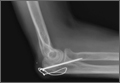
American Academy of Orthopaedic Surgeons Disclosure Policy Fails to Accurately Inform Its Members of Potential Conflicts of Interest
The relationship and collaboration between orthopedic surgeons and the orthopedic industry are considerable. Orthopedic surgeons can provide companies with important clinical input into the design of implants, facilitate commercialization of innovations developed by clinician entrepreneurs, and help provide rapid dissemination of new technologies.1,2 However, these relationships can result in conflicts of interest, thereby influencing the physicians’ judgment and choices and ultimately patient care.3,4 Making these potential conflicts transparent through physician disclosures is an accepted way to limit the negative effects of these relationships.5 The relationship between orthopedic surgeons and industry was brought to the forefront in 2007 with a settlement between the US Department of Justice (DOJ) and the 5 largest orthopedic implant makers.6 Among other things, this settlement required that each company publicly disclose on its website, beginning in 2008, the names and locations of all surgeons and organizations it paid, and how much. The DOJ settlement was one of the impetuses that led many orthopedic societies to adopt either voluntary or mandatory disclosure policies for their members.
In 2007, the American Academy of Orthopaedic Surgeons (AAOS) developed an orthopedic disclosure program to promote transparency and confidence in its educational programs and decisions.7 One of the 2 main purposes of the disclosure program is “streamlining the disclosure process for orthopedic surgeons and others involved in organizational governance, all formats of continuing medical education [CME] and authors of enduring materials, clinical practice guidelines (CPG) and appropriate use criteria (AUC) development and editors-in-chief and editorial boards, from whom disclosure is required.”8 Disclosure is mandatory only for participants in the AAOS CME programs (including any podium or poster presentation) or authors of enduring materials; members of the AAOS Board of Directors, Board of Councilors, Board of Specialty Societies, councils, cabinets, committees, project teams, or other AAOS governance groups; editors-in-chief and editorial boards; and AAOS guideline development workgroups. Members who fail to disclose are informed they cannot participate in AAOS activities. All other members of the organization are not required to disclose any industry-related relationships, and any disclosure is completely voluntary.7 This seems contrary to the second main goal of the disclosure policy: “increase transparency throughout AAOS by making this disclosure program available to the public and to AAOS members.”8
We conducted a study to compare the disclosures posted by the top orthopedic companies with the disclosures made by their surgeon-consultants and to determine how many of these surgeons have disclosed this information on the AAOS website.
Materials and Methods
On November 26, 2012, we reviewed the websites of the top 13 orthopedic device companies by revenue (Stryker, DePuy Orthopaedics, Zimmer Holdings, Smith & Nephew, Synthes, Medtronic Spine, Biomet, DJO Global, Orthofix, NuVasive, Wright Medical Group, ArthroCare, Exactech)9 to identify their surgeon-consultants for 2011. We excluded non-US surgeons (DOJ disclosure not required), revenues under $1000, and reimbursement for meals and travel. Although the DOJ settlement required that each company disclose on its website, beginning in 2008, the names and locations of its paid consultants and the amounts paid, the settlement did not stipulate how long this must be continued. Of the 13 companies, only 6 (Stryker, DePuy, Smith & Nephew, Medtronic, Wright, Exactech) continued listing and updating surgeon disclosure information.
As the companies differed in how they defined surgeon consulting services, we defined surgeon-consultant payments as the sum of consulting payments, royalty payments, and research support. We searched for each surgeon-consultant’s name in the AAOS orthopedic disclosure program database.7 From the database, we determined whether the surgeon was a member of AAOS. All members were then categorized into those who disclosed all their payments, those who incompletely disclosed their payments, those who did not disclose any payments, and those who did not provide any information. They were then subdivided into those who had and had not participated in CME activities at the AAOS annual meeting in 2011 (participants were listed in the meeting proceedings). This does not take into account AAOS members who presented at other AAOS-sponsored CME courses during 2011 and who therefore were required to disclose. The information was categorized by company, payment amount, and overall. To simplify matters and deal with varying corporate categories, we divided payments into 4 amount groups: less than $10,000, $10,000 to $100,000, $100,001 to $1 million, and more than $1 million. Some orthopedic companies reported surgeon payments as categorical rather than exact amounts. In these cases, we coded the payment as the midpoint of the range.
Results
Overall, 549 AAOS members received payments of more than $1000 from at least 1 of the 6 companies. Of these surgeons, 307 (56%) fully disclosed their payments, and 242 (44%) did not (Table 1). Of the 32 surgeons who were on 2 corporate payment lists, 24 disclosed both companies, 6 disclosed only 1 company, and 2 failed to disclose either company. AAOS members who did not disclose payments received less than $10,000 (average, $3706) in 37% of cases (Table 2), between $10,000 and $100,000 (average, $34,025) in 54% of cases, between $100,001 and $1 million (average, $290,505) in 8% of cases, and more than $1 million (average, $5,126,000) in less than 1% of cases.
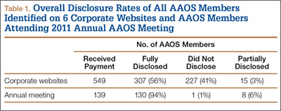
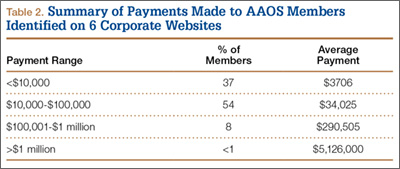
Number of consultants, number of surgeons not disclosing payments, and value of these payments varied from company to company (Table 3). The company with the most consultants listed 185 AAOS members, of which 37% had not disclosed payments (average, $39,604). Second was the company that listed 108 members; 39% had not disclosed payments (average, $38,426). The third company listed 102 members, of which 56% had not disclosed payments (average, $217,340). The company with the fourth most consultants listed 84 members; 43% had not disclosed payments (average, $9841). Next to last was the company listing 42 members, of which 52% had not disclosed payments (average, $160,634). The company with the fewest consultants listed 28 members; 61% had not disclosed payments (average $85,388).
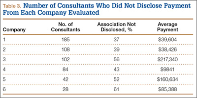
Of AAOS members who attended the 2011 annual meeting, 94% fully disclosed industry payments (Table 1). Only 7% of the membership either failed to disclose or incompletely disclosed this relationship. In 36 cases (26%), members disclosed a financial relationship with at least 1 orthopedic company, but this relationship was not listed on the company’s website. One of the companies was responsible for 47% of the underreporting.
Discussion
In this study, we evaluated whether surgeons fully disclosed (on the website for the AAOS disclosure program) payments they received from orthopedic companies. Overall compliance was poor, with 44% of surgeons not disclosing payments. The percentage of surgeons disclosing corporate relationships and payments received varied among orthopedic companies. It is unclear whether this reflects partial reporting, or AAOS disclosure policy being mandatory only for select members rather than the entire membership.
This study had a few limitations, none of which had a substantive impact on the results or conclusions. First, we could not determine how many AAOS members who were required to disclose actually disclosed. There is no mechanism for determining which members are involved in activities that require disclosure. Nonetheless, the intent of the policy is to make collaborations between orthopedic surgeons and industry transparent in order to address concerns about potential conflicts of interest. That 44% of AAOS members did not disclose their relationships cannot be considered a success. Second, information was available on the websites of only 6 of the top 15 orthopedic companies—a result stemming from the DOJ’s failure to specify how long these companies must continue posting disclosures. In this study, the lowest nondisclosure rate was 37%, and there is no reason to suspect that any other group of surgeon-consultants would be any more compliant with AAOS’s policy.
There are few reports on the effects of the DOJ settlement on the behavior of surgeon-consultants who are AAOS members. Hockenberry and colleagues10 found that, since the settlement, surgeon payments have increased, number of consultants has decreased, and the proportion of consultants from academia has increased. They thought their findings confirmed concerns that orthopedic device makers would deliberately select high-volume orthopedic surgeons as consultants in order to increase sales of their implants and gain market share at the expense of their competitors. The authors thought that AAOS had some power to address disclosure through its influence on its members, but that influence may not be enough. Jegede and colleagues11 found that a significant percentage (41%) of orthopedic surgeons who received corporate payments and presented at the AAOS annual meeting were inconsistent in submitting disclosure information. Results of the present study suggest that AAOS policy is weak and does not adequately address the issue and provide full transparency, either within the organization or to the public, of all its members’ industry relationships.
As the preeminent provider of musculoskeletal education to orthopedic surgeons and others, and with a membership totaling almost 39,000, AAOS is one of the most important orthopedic societies in the world. AAOS has clearly stated that one of its goals is to increase transparency by making its surgeon disclosure program available to AAOS members and the public. However, it can be completely transparent only if all its members are required to disclose their corporate relationships. This study demonstrated that AAOS’s policy of mandatory disclosure for select members and voluntary disclosure for all other members is ineffective. We found that 44% of members failed to disclose industry-derived payments. This inadequate level of compliance runs contrary to the AAOS goal of increasing transparency of surgeon–industry consulting by making its surgeon disclosure program available to AAOS members and the public. The AAOS disclosure program and the potential consequences of noncompliance need to be reevaluated by the organization if it wants its program to succeed.
1. Crowninshield RD, Callaghan JJ. The orthopaedic profession and the industry partnership. Clin Orthop Relat Res. 2007;(457):73-77.
2. White AP, Vaccaro AR, Zdeblick T. Counterpoint: physician–industry relationships can be ethically established, and conflicts of interest can be ethically managed. Spine. 2007;32(11 suppl):S53-S57.
3. Steinbrook R. Online disclosure of physician–industry relationships. N Engl J Med. 2009;360(4):325-327.
4. Steinbrook R. Disclosure of industry payments to physicians. N Engl J Med. 2008;359(6):559-561.
5. Weinfurt KP, Friedman JY, Dinan MA, et al. Disclosing conflicts of interest in clinical research: views of institutional review boards, conflict of interest committees, and investigators. J Law Med Ethics. 2006;34(3):581-591, 481.
6. US Attorney’s Office, District of New Jersey. Monitoring and deferred prosecution agreements terminated with companies in hip and knee replacement industry [press release]. Federal Bureau of Investigation, Newark Division website. http://www.fbi.gov/newark/press-releases/2009/nk033009a.htm. March 30, 2009. Accessed May 13, 2015.
7. AAOS mandatory disclosure policy. American Academy of Orthopaedic Surgeons website. http://www.aaos.org/about/policies/DisclosurePolicy.asp. Adopted February 2007. Revised December 2009, February 2012. Accessed May 13, 2015.
8. The AAOS orthopaedic disclosure program. American Academy of Orthopaedic Surgeons website. http://www7.aaos.org/education/disclosure. Accessed May 13, 2015.
9. Top 15 ortho companies by revenue [based on 2011 full-year financials]. OrthoStreams website. http://orthostreams.com/top-15-ortho-companies-by-revenue/http://orthostreams.com/2012/03/the-top-15-orthopedic-companies-ranked-by-2011 revenue/. Accessed May 13, 2015.
10. Hockenberry JM, Weigel P, Auerbach A, Cram P. Financial payments by orthopedic device makers to orthopedic surgeons. Arch Intern Med. 2011;171(19):1759-1765.
11. Jegede KA, Ju B, Miller CP, Whang P, Grauer JN. Quantifying the variability of financial disclosure information reported by authors presenting research at multiple sports medicine conferences. Am J Orthop. 2011;40(11):583-587.
The relationship and collaboration between orthopedic surgeons and the orthopedic industry are considerable. Orthopedic surgeons can provide companies with important clinical input into the design of implants, facilitate commercialization of innovations developed by clinician entrepreneurs, and help provide rapid dissemination of new technologies.1,2 However, these relationships can result in conflicts of interest, thereby influencing the physicians’ judgment and choices and ultimately patient care.3,4 Making these potential conflicts transparent through physician disclosures is an accepted way to limit the negative effects of these relationships.5 The relationship between orthopedic surgeons and industry was brought to the forefront in 2007 with a settlement between the US Department of Justice (DOJ) and the 5 largest orthopedic implant makers.6 Among other things, this settlement required that each company publicly disclose on its website, beginning in 2008, the names and locations of all surgeons and organizations it paid, and how much. The DOJ settlement was one of the impetuses that led many orthopedic societies to adopt either voluntary or mandatory disclosure policies for their members.
In 2007, the American Academy of Orthopaedic Surgeons (AAOS) developed an orthopedic disclosure program to promote transparency and confidence in its educational programs and decisions.7 One of the 2 main purposes of the disclosure program is “streamlining the disclosure process for orthopedic surgeons and others involved in organizational governance, all formats of continuing medical education [CME] and authors of enduring materials, clinical practice guidelines (CPG) and appropriate use criteria (AUC) development and editors-in-chief and editorial boards, from whom disclosure is required.”8 Disclosure is mandatory only for participants in the AAOS CME programs (including any podium or poster presentation) or authors of enduring materials; members of the AAOS Board of Directors, Board of Councilors, Board of Specialty Societies, councils, cabinets, committees, project teams, or other AAOS governance groups; editors-in-chief and editorial boards; and AAOS guideline development workgroups. Members who fail to disclose are informed they cannot participate in AAOS activities. All other members of the organization are not required to disclose any industry-related relationships, and any disclosure is completely voluntary.7 This seems contrary to the second main goal of the disclosure policy: “increase transparency throughout AAOS by making this disclosure program available to the public and to AAOS members.”8
We conducted a study to compare the disclosures posted by the top orthopedic companies with the disclosures made by their surgeon-consultants and to determine how many of these surgeons have disclosed this information on the AAOS website.
Materials and Methods
On November 26, 2012, we reviewed the websites of the top 13 orthopedic device companies by revenue (Stryker, DePuy Orthopaedics, Zimmer Holdings, Smith & Nephew, Synthes, Medtronic Spine, Biomet, DJO Global, Orthofix, NuVasive, Wright Medical Group, ArthroCare, Exactech)9 to identify their surgeon-consultants for 2011. We excluded non-US surgeons (DOJ disclosure not required), revenues under $1000, and reimbursement for meals and travel. Although the DOJ settlement required that each company disclose on its website, beginning in 2008, the names and locations of its paid consultants and the amounts paid, the settlement did not stipulate how long this must be continued. Of the 13 companies, only 6 (Stryker, DePuy, Smith & Nephew, Medtronic, Wright, Exactech) continued listing and updating surgeon disclosure information.
As the companies differed in how they defined surgeon consulting services, we defined surgeon-consultant payments as the sum of consulting payments, royalty payments, and research support. We searched for each surgeon-consultant’s name in the AAOS orthopedic disclosure program database.7 From the database, we determined whether the surgeon was a member of AAOS. All members were then categorized into those who disclosed all their payments, those who incompletely disclosed their payments, those who did not disclose any payments, and those who did not provide any information. They were then subdivided into those who had and had not participated in CME activities at the AAOS annual meeting in 2011 (participants were listed in the meeting proceedings). This does not take into account AAOS members who presented at other AAOS-sponsored CME courses during 2011 and who therefore were required to disclose. The information was categorized by company, payment amount, and overall. To simplify matters and deal with varying corporate categories, we divided payments into 4 amount groups: less than $10,000, $10,000 to $100,000, $100,001 to $1 million, and more than $1 million. Some orthopedic companies reported surgeon payments as categorical rather than exact amounts. In these cases, we coded the payment as the midpoint of the range.
Results
Overall, 549 AAOS members received payments of more than $1000 from at least 1 of the 6 companies. Of these surgeons, 307 (56%) fully disclosed their payments, and 242 (44%) did not (Table 1). Of the 32 surgeons who were on 2 corporate payment lists, 24 disclosed both companies, 6 disclosed only 1 company, and 2 failed to disclose either company. AAOS members who did not disclose payments received less than $10,000 (average, $3706) in 37% of cases (Table 2), between $10,000 and $100,000 (average, $34,025) in 54% of cases, between $100,001 and $1 million (average, $290,505) in 8% of cases, and more than $1 million (average, $5,126,000) in less than 1% of cases.
Number of consultants, number of surgeons not disclosing payments, and value of these payments varied from company to company (Table 3). The company with the most consultants listed 185 AAOS members, of which 37% had not disclosed payments (average, $39,604). Second was the company that listed 108 members; 39% had not disclosed payments (average, $38,426). The third company listed 102 members, of which 56% had not disclosed payments (average, $217,340). The company with the fourth most consultants listed 84 members; 43% had not disclosed payments (average, $9841). Next to last was the company listing 42 members, of which 52% had not disclosed payments (average, $160,634). The company with the fewest consultants listed 28 members; 61% had not disclosed payments (average $85,388).
Of AAOS members who attended the 2011 annual meeting, 94% fully disclosed industry payments (Table 1). Only 7% of the membership either failed to disclose or incompletely disclosed this relationship. In 36 cases (26%), members disclosed a financial relationship with at least 1 orthopedic company, but this relationship was not listed on the company’s website. One of the companies was responsible for 47% of the underreporting.
Discussion
In this study, we evaluated whether surgeons fully disclosed (on the website for the AAOS disclosure program) payments they received from orthopedic companies. Overall compliance was poor, with 44% of surgeons not disclosing payments. The percentage of surgeons disclosing corporate relationships and payments received varied among orthopedic companies. It is unclear whether this reflects partial reporting, or AAOS disclosure policy being mandatory only for select members rather than the entire membership.
This study had a few limitations, none of which had a substantive impact on the results or conclusions. First, we could not determine how many AAOS members who were required to disclose actually disclosed. There is no mechanism for determining which members are involved in activities that require disclosure. Nonetheless, the intent of the policy is to make collaborations between orthopedic surgeons and industry transparent in order to address concerns about potential conflicts of interest. That 44% of AAOS members did not disclose their relationships cannot be considered a success. Second, information was available on the websites of only 6 of the top 15 orthopedic companies—a result stemming from the DOJ’s failure to specify how long these companies must continue posting disclosures. In this study, the lowest nondisclosure rate was 37%, and there is no reason to suspect that any other group of surgeon-consultants would be any more compliant with AAOS’s policy.
There are few reports on the effects of the DOJ settlement on the behavior of surgeon-consultants who are AAOS members. Hockenberry and colleagues10 found that, since the settlement, surgeon payments have increased, number of consultants has decreased, and the proportion of consultants from academia has increased. They thought their findings confirmed concerns that orthopedic device makers would deliberately select high-volume orthopedic surgeons as consultants in order to increase sales of their implants and gain market share at the expense of their competitors. The authors thought that AAOS had some power to address disclosure through its influence on its members, but that influence may not be enough. Jegede and colleagues11 found that a significant percentage (41%) of orthopedic surgeons who received corporate payments and presented at the AAOS annual meeting were inconsistent in submitting disclosure information. Results of the present study suggest that AAOS policy is weak and does not adequately address the issue and provide full transparency, either within the organization or to the public, of all its members’ industry relationships.
As the preeminent provider of musculoskeletal education to orthopedic surgeons and others, and with a membership totaling almost 39,000, AAOS is one of the most important orthopedic societies in the world. AAOS has clearly stated that one of its goals is to increase transparency by making its surgeon disclosure program available to AAOS members and the public. However, it can be completely transparent only if all its members are required to disclose their corporate relationships. This study demonstrated that AAOS’s policy of mandatory disclosure for select members and voluntary disclosure for all other members is ineffective. We found that 44% of members failed to disclose industry-derived payments. This inadequate level of compliance runs contrary to the AAOS goal of increasing transparency of surgeon–industry consulting by making its surgeon disclosure program available to AAOS members and the public. The AAOS disclosure program and the potential consequences of noncompliance need to be reevaluated by the organization if it wants its program to succeed.
1. Crowninshield RD, Callaghan JJ. The orthopaedic profession and the industry partnership. Clin Orthop Relat Res. 2007;(457):73-77.
2. White AP, Vaccaro AR, Zdeblick T. Counterpoint: physician–industry relationships can be ethically established, and conflicts of interest can be ethically managed. Spine. 2007;32(11 suppl):S53-S57.
3. Steinbrook R. Online disclosure of physician–industry relationships. N Engl J Med. 2009;360(4):325-327.
4. Steinbrook R. Disclosure of industry payments to physicians. N Engl J Med. 2008;359(6):559-561.
5. Weinfurt KP, Friedman JY, Dinan MA, et al. Disclosing conflicts of interest in clinical research: views of institutional review boards, conflict of interest committees, and investigators. J Law Med Ethics. 2006;34(3):581-591, 481.
6. US Attorney’s Office, District of New Jersey. Monitoring and deferred prosecution agreements terminated with companies in hip and knee replacement industry [press release]. Federal Bureau of Investigation, Newark Division website. http://www.fbi.gov/newark/press-releases/2009/nk033009a.htm. March 30, 2009. Accessed May 13, 2015.
7. AAOS mandatory disclosure policy. American Academy of Orthopaedic Surgeons website. http://www.aaos.org/about/policies/DisclosurePolicy.asp. Adopted February 2007. Revised December 2009, February 2012. Accessed May 13, 2015.
8. The AAOS orthopaedic disclosure program. American Academy of Orthopaedic Surgeons website. http://www7.aaos.org/education/disclosure. Accessed May 13, 2015.
9. Top 15 ortho companies by revenue [based on 2011 full-year financials]. OrthoStreams website. http://orthostreams.com/top-15-ortho-companies-by-revenue/http://orthostreams.com/2012/03/the-top-15-orthopedic-companies-ranked-by-2011 revenue/. Accessed May 13, 2015.
10. Hockenberry JM, Weigel P, Auerbach A, Cram P. Financial payments by orthopedic device makers to orthopedic surgeons. Arch Intern Med. 2011;171(19):1759-1765.
11. Jegede KA, Ju B, Miller CP, Whang P, Grauer JN. Quantifying the variability of financial disclosure information reported by authors presenting research at multiple sports medicine conferences. Am J Orthop. 2011;40(11):583-587.
Image-Based Techniques for Percutaneous Iliosacral Screw Start-Site Localization
Iliosacral (SI) screws remain the standard of care for the vast majority of posterior pelvic ring disruptions.1,2 However, despite their routine use, the procedure remains technically demanding with repeated cases of aberrant screw placement and complications.3,4 Sacral morphology is extremely variable within a patient population and affects accurate placement and trajectory of percutaneous screws.5 Classically, it is taught that the external starting position/landmark is at an intersection point of the greater trochanter and the anterior superior iliac spine (ASIS). While this “one size fits all” approach will certainly help to coordinate a start position, it is our experience that multiple stab incisions are necessary to find the optimal start site. To our knowledge, the most common image-based technique used to guide start-point localization and placement of SI screws begins with drawing a virtual sacrum on the patient’s side, guided by the lateral image.5 This article provides a novel image-based technique to be used with, or as a replacement for, the traditional technique.
Techniques
The patient is brought to the operating room and placed supine on a radiolucent operating table. If the closed reduction of the pelvic ring is successful or can be achieved via anterior manipulation/traction, posterior percutaneous pinning is planned. Either a rolled towel or a bag of saline is used as a bolster and placed midline underneath the sacrum and lumbar spine to help “bump” the pelvis and improve the range of motion for the surgeon’s drill. The patient is brought to the edge of the table when possible (ie, a posterior ring injury requiring fixation from only 1 side) to further enhance drill motion. If bilateral screws are planned, surgeons must be careful not to position 1 side at the expense of screw placement on the contralateral side. Nitrous-based anesthetic agents are avoided, because they may collect in the bowel and obscure good radiographic visualization. Arms are placed perpendicular to the body to facilitate the inlet view. Pre-preparation anteroposterior pelvis, inlet, and outlet views are obtained to assure ability to accurately and safely assess landmarks on all projections, and to mark the C-arm position and angles. This process helps decrease “useless” radiographs obtained during the procedure. Acceptable inlet radiographs show the anterior cortex of the S1 body superimposed on the S2 body. Acceptable outlet radiographs show the superior pubic symphysis at the level of the S2 foramen and visualization of the S1/S2 sacral foramen.6 The patient is then prepared in the standard fashion. Reduction maneuvers are performed and, if acceptable alignment is achieved, posterior percutaneous screw placement begins.
Technique 1
To our knowledge, the most common image-based technique used to guide start-point localization and placement of SI screws begins with drawing a virtual sacrum on the patient’s side using the lateral image. The fluoroscopic machine is set up in a lateral position.5 A free guide wire is superimposed upon the iliac cortical density and anterior sacral slope, which is marked on the skin (Figure 1). The superior portion of S1, as well as the posterior sacral slope, can be marked as well. This process has outlined the sacrum and provides an external landmark for the “safe zone” for screw placement. The operation proceeds in the standard fashion using inlet, outlet, and lateral radiographs. However, the externally drawn sacrum can aid as a reference during guide-pin placement.
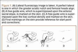
Technique 2
This technique takes into account bone anatomy and soft-tissue coverage. It is helpful to think of the abdomen/pelvis as a box. The anterior abdomen represents the top of the box and the lateral buttock represents the side of the box. The corner of the imaginary box is where the abdomen begins to slope down and transitions laterally to become the buttock. This will be referenced as the “down-sloping point” and typically corresponds to the level of the iliac crest (Figure 2).
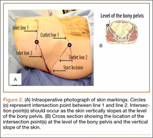
To begin, a standard cannulated screw guide wire is placed flush on the skin of the abdomen. An inlet fluoroscopy image is taken with the guide pin on the abdomen. Imagine that the resulting image represents the planned screw trajectory (Figure 3A). When the position of the guide wire is deemed adequate, a line is marked on the abdomen, using a pen, directly adjacent to the guide wire. This line represents inlet line 1 (Figure 2). The line must continue laterally until the down-sloping point. The sagittal angle of the imaginary inlet fluoroscopic beam is noted, and a guide wire is placed in the same sagittal orientation flush with the skin on the lateral buttock (Figure 3B). The guide wire must be placed so that it intersects with the first line at the down-sloping point. The skin on the lateral aspect of buttock is marked with a second line, which represents inlet line 2 (Figure 2).
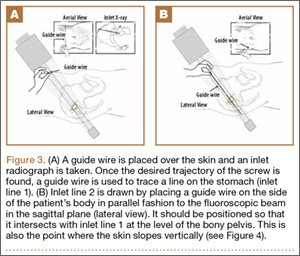
The same process is repeated using an outlet view to create outlet lines 1 and 2 (Figures 4A, 4B). At this point there are 4 lines drawn on the patient (Figure 2). A stab incision is made at the intersection of the 2 lines drawn on the lateral buttock; this represents the skin start point, labeled “start incision” (Figure 2). The procedure continues in standard fashion.
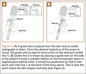
The 4 external reference lines serve multiple purposes. First, the lines mark the true lateral start point for the pin at the level of the skin. This contrasts with the standard technique in which bony landmarks are marked on the skin and the surgeon must estimate a point on the skin that will provide an appropriate trajectory to the bony start point on the ilium. Further, the lines can also be used to reorient the cartesian plane so that adjustments can be isolated to a single plane, ensuring movements only alter the position on a single radiographic view (Figure 5).
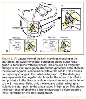
Discussion
Despite the widespread use of percutaneous screw placement for posterior pelvic ring injuries, this remains a technically demanding surgery. Recent data suggest patient pelvic anatomy is extremely varied, especially the sacrum.7 Further, screw trajectories vary depending on surgical goals, fracture pattern, and number of screws. Taken together, this implies that there is no perfect universal starting site along the external ilium. Therefore, while classic teaching states to begin screw insertion within the vicinity of the intersection of the greater trochanter and the ASIS, it is our experience that this location is often not ideal.
The inlet, outlet, and lateral radiographs are all vital to assess correct trajectory of the guide pin and drill prior to final screw insertion, but the start site remains a critical step to assure a successful surgical outcome. We present 2 techniques, used together or separately, that allow the surgeon to place the initial guide pin more accurately for percutanous iliosacral screws. Though not specifically examined in this study, we think technique 2 has the potential to save operative time and use less fluoroscopic imaging because a lateral image is not required until later in the case. Technique 2 identifies the start point at the level of the skin. This is in contrast to technique 1, which identifies the desired sacral target and requires a surgeon to select a skin start site that will provide an optimal trajectory towards the desired target. Judging trajectory can be difficult, particularly in obese patients, and technique 2 eliminates this extra variable.
It is also important to consider that criteria-based nonorthogonal imaging is required for percutaneous screw placement. In these cases, it is more difficult to judge trajectory corrections because the fluoroscopic beam cannot guide perpendicular corrections as it can in operations that use orthogonal imaging. Adjustments made perpendicular to the fluoroscopic beam will change trajectory in multiple planes.8 Moreover, because the standard cartesian frame of reference is rotated, understanding the location of the sacrum in space can be especially challenging. When using the first technique, sacral landmarks are delineated, and a virtual sacrum drawn on the patient’s exterior helps with orientation. In the second technique, the ideal pin placement is mapped, and the external reference lines guide uniplanar changes. For example, the line drawn co-planar with the inlet view is essentially marking the sacral slope. Therefore, by following this line, uniplanar changes in the cranial and caudal direction are achieved on the outlet view (Figure 5). Because this line is also in reference to the already known ideal pin placement, ideal pin placement can be maintained in 1 radiographic projection while changing the start site in the appropriate direction. In a similar fashion, the co-planar line identified on the inlet view can be used on the outlet image to affect uniplanar changes in the anteroposterior direction. This technique effectively minimizes disorientation when placing percutaneous SI screws. This can be particularly beneficial when placing screws in the prone position.
Conclusion
We have shown 2 techniques that are routinely used at our institution to help identify an accurate starting position for percutaneous screw placement in posterior pelvic ring injuries. Even experienced traumatologists can more quickly and accurately identify the correct stab incisions leading to more confidently placed screws. Further, we believe understanding the usage of fluoroscopy and the concepts involved in drawing the lines enhance trainees’ comprehension of the complex anatomy of the sacrum.
1. Matta JM, Saucedo T. Internal fixation of pelvic ring fractures. Clin Orthop Relat Res. 1989;242:83-97.
2. Routt ML Jr, Kregor PJ, Simonian PT, Mayo KA. Early results of percutaneous iliosacral screws placed with the patient in the supine position. J Orthop Trauma. 1995;9(3):207-214.
3. Sagi HC, Lindvall EM. Inadvertent intraforaminal iliosacral screw placement despite apparent appropriate positioning on intraoperative fluoroscopy.
J Orthop Trauma. 2005;19(2):130-133.
4. Routt ML Jr, Simonian PT, Mills WJ. Iliosacral screw fixation: early complications of the percutaneous technique. J Orthop Trauma. 1997;11(8):584-589.
5. Routt ML Jr, Simonian PT, Agnew SG, Mann FA. Radiographic recognition of the sacral alar slope for optimal placement of iliosacral screws: a cadaveric and clinical study. J Orthop Trauma. 1996;10(3):171-177.
6. Gardner MJ, Ferrell ED, Nork SE, Segina DN, Routt ML Jr. Percutaneous placement of iliosacral screws without electrodiagnostic monitoring. J Trauma. 2009;66(5):1411-1415.
7. Miller AN, Routt ML Jr. Variations in sacral morphology and implications for iliosacral screw fixation. J Am Acad Orthop Surg. 2012;20(1):8-16.
8. Graves ML, Routt ML. Iliosacral screw placement: are uniplanar changes realistic based on standard fluoroscopic imaging? J Orthop Trauma. 2011;71(1):204-208.
Iliosacral (SI) screws remain the standard of care for the vast majority of posterior pelvic ring disruptions.1,2 However, despite their routine use, the procedure remains technically demanding with repeated cases of aberrant screw placement and complications.3,4 Sacral morphology is extremely variable within a patient population and affects accurate placement and trajectory of percutaneous screws.5 Classically, it is taught that the external starting position/landmark is at an intersection point of the greater trochanter and the anterior superior iliac spine (ASIS). While this “one size fits all” approach will certainly help to coordinate a start position, it is our experience that multiple stab incisions are necessary to find the optimal start site. To our knowledge, the most common image-based technique used to guide start-point localization and placement of SI screws begins with drawing a virtual sacrum on the patient’s side, guided by the lateral image.5 This article provides a novel image-based technique to be used with, or as a replacement for, the traditional technique.
Techniques
The patient is brought to the operating room and placed supine on a radiolucent operating table. If the closed reduction of the pelvic ring is successful or can be achieved via anterior manipulation/traction, posterior percutaneous pinning is planned. Either a rolled towel or a bag of saline is used as a bolster and placed midline underneath the sacrum and lumbar spine to help “bump” the pelvis and improve the range of motion for the surgeon’s drill. The patient is brought to the edge of the table when possible (ie, a posterior ring injury requiring fixation from only 1 side) to further enhance drill motion. If bilateral screws are planned, surgeons must be careful not to position 1 side at the expense of screw placement on the contralateral side. Nitrous-based anesthetic agents are avoided, because they may collect in the bowel and obscure good radiographic visualization. Arms are placed perpendicular to the body to facilitate the inlet view. Pre-preparation anteroposterior pelvis, inlet, and outlet views are obtained to assure ability to accurately and safely assess landmarks on all projections, and to mark the C-arm position and angles. This process helps decrease “useless” radiographs obtained during the procedure. Acceptable inlet radiographs show the anterior cortex of the S1 body superimposed on the S2 body. Acceptable outlet radiographs show the superior pubic symphysis at the level of the S2 foramen and visualization of the S1/S2 sacral foramen.6 The patient is then prepared in the standard fashion. Reduction maneuvers are performed and, if acceptable alignment is achieved, posterior percutaneous screw placement begins.
Technique 1
To our knowledge, the most common image-based technique used to guide start-point localization and placement of SI screws begins with drawing a virtual sacrum on the patient’s side using the lateral image. The fluoroscopic machine is set up in a lateral position.5 A free guide wire is superimposed upon the iliac cortical density and anterior sacral slope, which is marked on the skin (Figure 1). The superior portion of S1, as well as the posterior sacral slope, can be marked as well. This process has outlined the sacrum and provides an external landmark for the “safe zone” for screw placement. The operation proceeds in the standard fashion using inlet, outlet, and lateral radiographs. However, the externally drawn sacrum can aid as a reference during guide-pin placement.
Technique 2
This technique takes into account bone anatomy and soft-tissue coverage. It is helpful to think of the abdomen/pelvis as a box. The anterior abdomen represents the top of the box and the lateral buttock represents the side of the box. The corner of the imaginary box is where the abdomen begins to slope down and transitions laterally to become the buttock. This will be referenced as the “down-sloping point” and typically corresponds to the level of the iliac crest (Figure 2).
To begin, a standard cannulated screw guide wire is placed flush on the skin of the abdomen. An inlet fluoroscopy image is taken with the guide pin on the abdomen. Imagine that the resulting image represents the planned screw trajectory (Figure 3A). When the position of the guide wire is deemed adequate, a line is marked on the abdomen, using a pen, directly adjacent to the guide wire. This line represents inlet line 1 (Figure 2). The line must continue laterally until the down-sloping point. The sagittal angle of the imaginary inlet fluoroscopic beam is noted, and a guide wire is placed in the same sagittal orientation flush with the skin on the lateral buttock (Figure 3B). The guide wire must be placed so that it intersects with the first line at the down-sloping point. The skin on the lateral aspect of buttock is marked with a second line, which represents inlet line 2 (Figure 2).
The same process is repeated using an outlet view to create outlet lines 1 and 2 (Figures 4A, 4B). At this point there are 4 lines drawn on the patient (Figure 2). A stab incision is made at the intersection of the 2 lines drawn on the lateral buttock; this represents the skin start point, labeled “start incision” (Figure 2). The procedure continues in standard fashion.
The 4 external reference lines serve multiple purposes. First, the lines mark the true lateral start point for the pin at the level of the skin. This contrasts with the standard technique in which bony landmarks are marked on the skin and the surgeon must estimate a point on the skin that will provide an appropriate trajectory to the bony start point on the ilium. Further, the lines can also be used to reorient the cartesian plane so that adjustments can be isolated to a single plane, ensuring movements only alter the position on a single radiographic view (Figure 5).
Discussion
Despite the widespread use of percutaneous screw placement for posterior pelvic ring injuries, this remains a technically demanding surgery. Recent data suggest patient pelvic anatomy is extremely varied, especially the sacrum.7 Further, screw trajectories vary depending on surgical goals, fracture pattern, and number of screws. Taken together, this implies that there is no perfect universal starting site along the external ilium. Therefore, while classic teaching states to begin screw insertion within the vicinity of the intersection of the greater trochanter and the ASIS, it is our experience that this location is often not ideal.
The inlet, outlet, and lateral radiographs are all vital to assess correct trajectory of the guide pin and drill prior to final screw insertion, but the start site remains a critical step to assure a successful surgical outcome. We present 2 techniques, used together or separately, that allow the surgeon to place the initial guide pin more accurately for percutanous iliosacral screws. Though not specifically examined in this study, we think technique 2 has the potential to save operative time and use less fluoroscopic imaging because a lateral image is not required until later in the case. Technique 2 identifies the start point at the level of the skin. This is in contrast to technique 1, which identifies the desired sacral target and requires a surgeon to select a skin start site that will provide an optimal trajectory towards the desired target. Judging trajectory can be difficult, particularly in obese patients, and technique 2 eliminates this extra variable.
It is also important to consider that criteria-based nonorthogonal imaging is required for percutaneous screw placement. In these cases, it is more difficult to judge trajectory corrections because the fluoroscopic beam cannot guide perpendicular corrections as it can in operations that use orthogonal imaging. Adjustments made perpendicular to the fluoroscopic beam will change trajectory in multiple planes.8 Moreover, because the standard cartesian frame of reference is rotated, understanding the location of the sacrum in space can be especially challenging. When using the first technique, sacral landmarks are delineated, and a virtual sacrum drawn on the patient’s exterior helps with orientation. In the second technique, the ideal pin placement is mapped, and the external reference lines guide uniplanar changes. For example, the line drawn co-planar with the inlet view is essentially marking the sacral slope. Therefore, by following this line, uniplanar changes in the cranial and caudal direction are achieved on the outlet view (Figure 5). Because this line is also in reference to the already known ideal pin placement, ideal pin placement can be maintained in 1 radiographic projection while changing the start site in the appropriate direction. In a similar fashion, the co-planar line identified on the inlet view can be used on the outlet image to affect uniplanar changes in the anteroposterior direction. This technique effectively minimizes disorientation when placing percutaneous SI screws. This can be particularly beneficial when placing screws in the prone position.
Conclusion
We have shown 2 techniques that are routinely used at our institution to help identify an accurate starting position for percutaneous screw placement in posterior pelvic ring injuries. Even experienced traumatologists can more quickly and accurately identify the correct stab incisions leading to more confidently placed screws. Further, we believe understanding the usage of fluoroscopy and the concepts involved in drawing the lines enhance trainees’ comprehension of the complex anatomy of the sacrum.
1. Matta JM, Saucedo T. Internal fixation of pelvic ring fractures. Clin Orthop Relat Res. 1989;242:83-97.
2. Routt ML Jr, Kregor PJ, Simonian PT, Mayo KA. Early results of percutaneous iliosacral screws placed with the patient in the supine position. J Orthop Trauma. 1995;9(3):207-214.
3. Sagi HC, Lindvall EM. Inadvertent intraforaminal iliosacral screw placement despite apparent appropriate positioning on intraoperative fluoroscopy.
J Orthop Trauma. 2005;19(2):130-133.
4. Routt ML Jr, Simonian PT, Mills WJ. Iliosacral screw fixation: early complications of the percutaneous technique. J Orthop Trauma. 1997;11(8):584-589.
5. Routt ML Jr, Simonian PT, Agnew SG, Mann FA. Radiographic recognition of the sacral alar slope for optimal placement of iliosacral screws: a cadaveric and clinical study. J Orthop Trauma. 1996;10(3):171-177.
6. Gardner MJ, Ferrell ED, Nork SE, Segina DN, Routt ML Jr. Percutaneous placement of iliosacral screws without electrodiagnostic monitoring. J Trauma. 2009;66(5):1411-1415.
7. Miller AN, Routt ML Jr. Variations in sacral morphology and implications for iliosacral screw fixation. J Am Acad Orthop Surg. 2012;20(1):8-16.
8. Graves ML, Routt ML. Iliosacral screw placement: are uniplanar changes realistic based on standard fluoroscopic imaging? J Orthop Trauma. 2011;71(1):204-208.
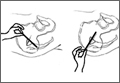
Advances in Stem Cell Research Lead to Osteoarthritis Treatment?
Researchers at the University of York in the United Kingdom, along with research colleagues at the Erasmus Medical Centre in Rotterdam, have identified individual stem cells that can regenerate tissue, cartilage, and bone, according to a study published June 9 in Stem Cell Reports.
Lead researcher Paul Genever, PhD, Senior Lecturer in the Department of Biology, and Head of the York site of the Arthritis Research UK Tissue Engineering Centre, said, “While stem cell therapy is an exciting new development for the treatment for osteoarthritis, up to now it has been something of a lottery because we did not know the precise properties of each of the cells.”

The study authors isolated individual marrow stromal cells and analyzed their different properties. This allowed the researchers to identify stem cells that are capable of repairing damaged cartilage or joint tissue. The York team also isolated a rare subset of stem cells in bone marrow that, while having no capability for tissue repair, appeared to have a prominent role in immune function.
“This project has helped us to establish which cells are good at regenerating tissue, cartilage, and bone, respectively. It will help in the search to develop more targeted therapies for arthritis patients, ” stated Dr. Genever.
Coauthor James Fox, PhD, said, “Working with colleagues across the Arthritis Research UK Tissue Engineering Centre will help to bring our discovery closer to patient treatment.”
Suggested Reading
James S, Fox J, Afsari F, et al. Multiparameter analysis of human bone marrow stromal cells identifies distinct immunomodulatory and differentiation-competent subtypes. Stem Cell Reports. 2015;4(6):1004-1015.
Researchers at the University of York in the United Kingdom, along with research colleagues at the Erasmus Medical Centre in Rotterdam, have identified individual stem cells that can regenerate tissue, cartilage, and bone, according to a study published June 9 in Stem Cell Reports.
Lead researcher Paul Genever, PhD, Senior Lecturer in the Department of Biology, and Head of the York site of the Arthritis Research UK Tissue Engineering Centre, said, “While stem cell therapy is an exciting new development for the treatment for osteoarthritis, up to now it has been something of a lottery because we did not know the precise properties of each of the cells.”
The study authors isolated individual marrow stromal cells and analyzed their different properties. This allowed the researchers to identify stem cells that are capable of repairing damaged cartilage or joint tissue. The York team also isolated a rare subset of stem cells in bone marrow that, while having no capability for tissue repair, appeared to have a prominent role in immune function.
“This project has helped us to establish which cells are good at regenerating tissue, cartilage, and bone, respectively. It will help in the search to develop more targeted therapies for arthritis patients, ” stated Dr. Genever.
Coauthor James Fox, PhD, said, “Working with colleagues across the Arthritis Research UK Tissue Engineering Centre will help to bring our discovery closer to patient treatment.”
Suggested Reading
James S, Fox J, Afsari F, et al. Multiparameter analysis of human bone marrow stromal cells identifies distinct immunomodulatory and differentiation-competent subtypes. Stem Cell Reports. 2015;4(6):1004-1015.
Suggested Reading
James S, Fox J, Afsari F, et al. Multiparameter analysis of human bone marrow stromal cells identifies distinct immunomodulatory and differentiation-competent subtypes. Stem Cell Reports. 2015;4(6):1004-1015.

Stronger Muscle Mass Equated With Healthier Bone Development
Lean mass gained during childhood is positively associated with bone size and trabecular volumetric bone mineral density at ages 6 and 7, according to a study published online ahead of print in the June issue of Bone.
For this study, detailed measurements of 200 children enrolled in the Southampton Women’s Survey were taken soon after birth and again at ages 6 and 7. Scanning equipment was used to assess bone mineral density, shape and size of the tibia, and body composition.
“Bone strength and size is important because they are significant factors in long-term osteoporosis and fracture risk,” said Rebecca Moon, BSc, lead investigator of the study.
The researchers found no relationship between fat mass and bone development, indicating that it is not an important factor in childhood skeletal strength. The investigators also found that the relationship between changes in lean muscle and bone development was stronger in girls than in boys, despite the ages of the children, ruling out the onset of puberty as a factor.
“A 10% increase in peak bone mass will delay the onset of osteoporosis by 13 years. These findings point to the importance of early childhood physical activity to optimize muscle and bone growth,” said Dr. Moon.
Suggested Reading
Moon RJ, Cole ZA, Crozier SR, et al. Longitudinal changes in lean mass predict pQCT measures of tibial geometry and mineralization at ages 6-7 years. Bone. 2015;75:105-110.
Lean mass gained during childhood is positively associated with bone size and trabecular volumetric bone mineral density at ages 6 and 7, according to a study published online ahead of print in the June issue of Bone.
For this study, detailed measurements of 200 children enrolled in the Southampton Women’s Survey were taken soon after birth and again at ages 6 and 7. Scanning equipment was used to assess bone mineral density, shape and size of the tibia, and body composition.
“Bone strength and size is important because they are significant factors in long-term osteoporosis and fracture risk,” said Rebecca Moon, BSc, lead investigator of the study.
The researchers found no relationship between fat mass and bone development, indicating that it is not an important factor in childhood skeletal strength. The investigators also found that the relationship between changes in lean muscle and bone development was stronger in girls than in boys, despite the ages of the children, ruling out the onset of puberty as a factor.
“A 10% increase in peak bone mass will delay the onset of osteoporosis by 13 years. These findings point to the importance of early childhood physical activity to optimize muscle and bone growth,” said Dr. Moon.
Suggested Reading
Moon RJ, Cole ZA, Crozier SR, et al. Longitudinal changes in lean mass predict pQCT measures of tibial geometry and mineralization at ages 6-7 years. Bone. 2015;75:105-110.
Suggested Reading
Moon RJ, Cole ZA, Crozier SR, et al. Longitudinal changes in lean mass predict pQCT measures of tibial geometry and mineralization at ages 6-7 years. Bone. 2015;75:105-110.
Poor Sleep, Negative Attitude, Amplify Pain in Knee Osteoarthritis
Patients with knee osteoarthritis (OA) who have poor sleep habits display greater central sensitization of pain, according to a study published online ahead of print June 4 in Arthritis Care & Research. Study findings also showed that OA patients who catastrophize had increased central sensitization that was associated with greater pain.
“Our study is the largest and most comprehensive examination of the relationship between sleep disturbance, catastrophizing, and central sensitization in knee OA,” stated lead author Claudia Campbell, PhD, an Associate Professor of Psychiatry and Behavioral Sciences at Johns Hopkins University School of Medicine in Baltimore.

The case-controlled study included 208 participants who were categorized according to 4 groups: patients who have OA and insomnia, patients who have OA and normal sleep habits, healthy controls with insomnia, and healthy controls without a pain syndrome and normal sleep. In all, 72% of the study’s participants were female.
Participants completed multimodal sleep assessments (eg, questionnaire, diary, actigraphy, and polysmnography) and extensive evaluation of pain using clinical measures and quantitative sensory testing to evaluate associations between central sensitization, catastrophizing, and insomnia.
Results showed that the participants with knee OA and insomnia had the greatest amount of central sensitization compared with controls. The team found patients with poor sleep and high catastrophizing scores reported increased levels of central sensitization. In turn, central sensitization was significantly associated with increased clinical pain.
“While no causal processes may be determined from this study, our data suggest that those with low sleep efficiency and higher catastrophizing have the greatest central sensitization. Understanding the intricate relationship between sleep, central sensitization, and catastrophizing has important clinical implications for treating those with chronic pain conditions such as knee OA,” Dr. Campbell stated.
Suggested Reading
Campbell CM, Buenaver LF, Finan P, et al. Sleep, pain catastrophizing and central sensitization in knee osteoarthritis patients with and without insomnia. Arthritis Care Res. 2015 June 4. [Epub ahead of print]
Patients with knee osteoarthritis (OA) who have poor sleep habits display greater central sensitization of pain, according to a study published online ahead of print June 4 in Arthritis Care & Research. Study findings also showed that OA patients who catastrophize had increased central sensitization that was associated with greater pain.
“Our study is the largest and most comprehensive examination of the relationship between sleep disturbance, catastrophizing, and central sensitization in knee OA,” stated lead author Claudia Campbell, PhD, an Associate Professor of Psychiatry and Behavioral Sciences at Johns Hopkins University School of Medicine in Baltimore.
The case-controlled study included 208 participants who were categorized according to 4 groups: patients who have OA and insomnia, patients who have OA and normal sleep habits, healthy controls with insomnia, and healthy controls without a pain syndrome and normal sleep. In all, 72% of the study’s participants were female.
Participants completed multimodal sleep assessments (eg, questionnaire, diary, actigraphy, and polysmnography) and extensive evaluation of pain using clinical measures and quantitative sensory testing to evaluate associations between central sensitization, catastrophizing, and insomnia.
Results showed that the participants with knee OA and insomnia had the greatest amount of central sensitization compared with controls. The team found patients with poor sleep and high catastrophizing scores reported increased levels of central sensitization. In turn, central sensitization was significantly associated with increased clinical pain.
“While no causal processes may be determined from this study, our data suggest that those with low sleep efficiency and higher catastrophizing have the greatest central sensitization. Understanding the intricate relationship between sleep, central sensitization, and catastrophizing has important clinical implications for treating those with chronic pain conditions such as knee OA,” Dr. Campbell stated.
Suggested Reading
Campbell CM, Buenaver LF, Finan P, et al. Sleep, pain catastrophizing and central sensitization in knee osteoarthritis patients with and without insomnia. Arthritis Care Res. 2015 June 4. [Epub ahead of print]
Suggested Reading
Campbell CM, Buenaver LF, Finan P, et al. Sleep, pain catastrophizing and central sensitization in knee osteoarthritis patients with and without insomnia. Arthritis Care Res. 2015 June 4. [Epub ahead of print]

FORCE-TJR Now Certified as CMS Qualified Clinical Data Registry
Function and Outcomes Research for Comparative Effectiveness in Total Joint Replacement and Quality Improvement (FORCE-TJR), the most comprehensive national registry for total hip and knee joint replacement patients and their outcomes, is now certified as a Qualified Clinical Data Registry (QCDR).
In meeting QCDR requirements, FORCE-TJR has successfully collected and tracked more than 30,000 patients with total joint replacements across the US, in more than 150 provider institutions. The FORCE-TJR registry continues to expand, providing patient and disease tracking, implant performance, patient-reported outcomes, and quality monitoring of total joint replacements.
With QCDR certification, FORCE-TJR is able to complete the collection and submission of Physician Quality Reporting System (PQRS) quality measures on behalf of member hospitals and physicians, allowing FORCE-TJR members to avoid the 2016 payment adjustment of 2.0%.
“The value of being involved in a registry such as FORCE-TJR is that I can concentrate on my patient and my practice,” said Courtland Lewis, MD, Orthopedic Surgery Chief, Department of Orthopedics, at Hartford Hospital and core member of FORCE-TJR. “FORCE-TJR makes it easy to capture and report this data to QCDR and PQRS for incentive payments, internal quality monitoring, and improving the value of the care we provide to patients and insurance plans.”

As part of this certification, FORCE-TJR has developed new non-PQRS measures, which include:
• Pain and functional status assessment for hip and knee replacements
• Improvement in pain and function after hip and knee replacements
• Assessment and improvement on patients with osteoarthritis in the hip or knee
• Mental health assessment for patients who undergo hip and knee replacements
“The new QCDR designation allows FORCE-TJR to define new quality measures, including patient-reported outcomes, and to submit these data to Centers for Medicare and Medicaid Services (CMS) on behalf of our members—without any additional data collection. The data serve both their internal quality monitoring and meet the CMS mandate,” said Patricia Franklin, MD, FORCE-TJR’s registry director.
FORCE-TJR, originally a 4-year, national research project funded by the Agency for Healthcare Research and Quality (AHRQ), is the first registry for total joint replacement to identify risk-adjusted national benchmarks, including patient risk factors, and other clinical measures, to guide surgeon and patient decisions regarding timing of surgery and optimal patient selection.
FORCE-TJR is now serving as a comprehensive orthopedic registry, expanding to enroll surgeons and hospitals beyond the original Agency for Healthcare Research and Quality-funded cohort.
In addition to assisting with reporting requirements and securing quality incentive payments, the FORCE-TJR registry provides access to national TJR benchmarks, real-time patient-reported outcome scoring, comprehensive, comparative arthroplasty practice feedback and data to improve patient care, and compare performance to peer surgeons and institutions.
Function and Outcomes Research for Comparative Effectiveness in Total Joint Replacement and Quality Improvement (FORCE-TJR), the most comprehensive national registry for total hip and knee joint replacement patients and their outcomes, is now certified as a Qualified Clinical Data Registry (QCDR).
In meeting QCDR requirements, FORCE-TJR has successfully collected and tracked more than 30,000 patients with total joint replacements across the US, in more than 150 provider institutions. The FORCE-TJR registry continues to expand, providing patient and disease tracking, implant performance, patient-reported outcomes, and quality monitoring of total joint replacements.
With QCDR certification, FORCE-TJR is able to complete the collection and submission of Physician Quality Reporting System (PQRS) quality measures on behalf of member hospitals and physicians, allowing FORCE-TJR members to avoid the 2016 payment adjustment of 2.0%.
“The value of being involved in a registry such as FORCE-TJR is that I can concentrate on my patient and my practice,” said Courtland Lewis, MD, Orthopedic Surgery Chief, Department of Orthopedics, at Hartford Hospital and core member of FORCE-TJR. “FORCE-TJR makes it easy to capture and report this data to QCDR and PQRS for incentive payments, internal quality monitoring, and improving the value of the care we provide to patients and insurance plans.”
As part of this certification, FORCE-TJR has developed new non-PQRS measures, which include:
• Pain and functional status assessment for hip and knee replacements
• Improvement in pain and function after hip and knee replacements
• Assessment and improvement on patients with osteoarthritis in the hip or knee
• Mental health assessment for patients who undergo hip and knee replacements
“The new QCDR designation allows FORCE-TJR to define new quality measures, including patient-reported outcomes, and to submit these data to Centers for Medicare and Medicaid Services (CMS) on behalf of our members—without any additional data collection. The data serve both their internal quality monitoring and meet the CMS mandate,” said Patricia Franklin, MD, FORCE-TJR’s registry director.
FORCE-TJR, originally a 4-year, national research project funded by the Agency for Healthcare Research and Quality (AHRQ), is the first registry for total joint replacement to identify risk-adjusted national benchmarks, including patient risk factors, and other clinical measures, to guide surgeon and patient decisions regarding timing of surgery and optimal patient selection.
FORCE-TJR is now serving as a comprehensive orthopedic registry, expanding to enroll surgeons and hospitals beyond the original Agency for Healthcare Research and Quality-funded cohort.
In addition to assisting with reporting requirements and securing quality incentive payments, the FORCE-TJR registry provides access to national TJR benchmarks, real-time patient-reported outcome scoring, comprehensive, comparative arthroplasty practice feedback and data to improve patient care, and compare performance to peer surgeons and institutions.

ICD-10 Race to the Finish: 8 High Priorities in the 11th Hour
As late as mid-April 2015, a survey of 121 orthopedic practices indicated that 30% had done nothing to start preparing for ICD-10 (International Classification of Diseases, Tenth Revision).1 That’s scary. And even the practices that had begun to prepare had not completed a number of key tasks (Figure 1).
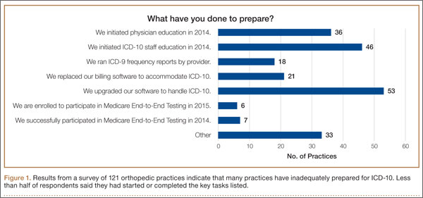
Certainly, the will-they-or-won’t-they possibility of another congressional delay had many practices sitting on their hands this year. But now that the October 1, 2015, implementation is set in stone, this lack of inertia has many practices woefully behind. If your practice is one of many that hasn’t mapped your common ICD-9 (International Classification of Diseases, Ninth Revision) codes to ICD-10 codes, completed payer testing, or attended training, it’s time for a “full-court press.”
Being unprepared for ICD-10 will cause more than just an increase in claim denials. If your surgery schedule is booked a few months out, your staff will need to pre-authorize cases using ICD-10 as early as August 1—and they won’t be able to do that if you haven’t dictated the clinical terms required to choose an ICD-10 code. Without an understanding of ICD-10, severity of illness coding will suffer, and that will affect your bundled and value-based payments. And, if you don’t provide an adequate diagnosis when sending patients off-site for physical therapy, you’ll soon be getting phone calls from their billing staff demanding more specifics.
The clock is ticking and time is short. Here’s a prioritized list of what needs to get done.
1. Generate an ICD-9 frequency report
Identifying which diagnosis codes are the most frequently used, and therefore drive a significant portion of practice revenue, is an absolute must. The data will help prioritize training and code-mapping activities.
Most practices generate Current Procedural Terminology (CPT) code-frequency reports regularly, but few have ever run an ICD-9 code-frequency report. Call your vendor and ask for assistance, as there are multiple ways to run this report and they vary by practice management system. Sort the data elements and generate the ICD-9 frequency report by:
- Primary diagnosis.
- Unique patient.
- Revenue. (If your practice management system can’t give you diagnosis data by revenue, which enables you to focus on the codes that generate the most revenue, generate it by charges.)
The result should be a report that identifies the 20 to 25 diagnosis codes (or charges, depending on the reports generated) that drive the most revenue for the practice. Use the data to focus and prioritize your training and code-mapping activities.
2. Schedule training
Forget about “general” ICD-10 training courses. You need orthopedic-specific guidance. That’s because ICD-10 for orthopedics is more complex than for other specialties. Dictating fractures under ICD-10 is not so simple. Selecting an injury code requires confidence in correctly using the seventh character.
“Everyone who uses diagnosis codes must have baseline knowledge: surgeons, billing staff, surgical coordinators, and clinical team,” according to Sarah Wiskerchen, MBA, CPC, consultant and ICD-10 educator with KarenZupko & Associates (KZA). Training must include the practical details of ICD-10, such as assigning laterality, understanding the system architecture, and limiting the use of unspecified codes.
The American Academy of Orthopaedic Surgeons (AAOS) offers a self-paced, online training series that provides details for the top 3 diagnosis codes for each subspecialty. The 10-program course, ICD-10-CM: By the Numbers, is available at www.aaos.org ($299 for members, $399 for nonmembers). If you prefer live instruction, there is one more AAOS-sponsored, regional ICD-10 workshop left before the October 1 deadline, and more may be added. (Details at www.karenzupko.com)
These courses provide highly specific and granular ICD-10 knowledge and incorporate the use of Code-X, an AAOS-developed software tool. They also feature tools for handling the complexities of fractures and injury codes, such as Leo C. Far, an acronym developed by KZA consultant and coding educator Margie Maley, BSN, MS, to make ICD-10 diagnosis coding for fractures easier (Figure 2).
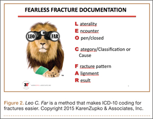
Some subspecialty societies also offer ICD-10 training. The American Society for Surgery of the Hand (www.assh.org), for example, offers a series of webinars and member-developed ICD-9-to-ICD-10 code maps.
3. Crosswalk your common codes from ICD-9 to ICD-10
Crosswalking is the process of mapping your most commonly used ICD-9 codes to their equivalent ICD-10 codes. This exercise familiarizes your team with ICD-10 language and terms, and gives a sense of which ICD-9 codes expand to just 1 or 2 ICD-10 codes and which codes expand into 10 or more codes—as some injury codes do (Table).
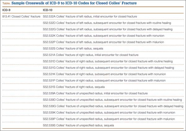
“Attempting to map the codes before completing ICD-10 training is like trying to write a letter in Greek when you only speak English,” Wiskerchen warns. “So start this process after at least some of your team have grasped the fundamentals of ICD-10.” This is where the data from your ICD-9 frequency report comes in. Use it to prioritize which codes to map first with a goal of mapping your top 25 ICD-9 codes to their ICD-10 equivalents by August 31.
Invest in good tools to support your mapping efforts. Avoid general mapping equivalent (GEM) coding tools, which are free for a good reason—they are incomplete and don’t always lead you to the correct ICD-10 code. Instead, purchase resources from credible sources, such as the American Medical Association (AMA; www.ama-assn.org). The AMA publishes ICD-10-CM 2016: The Complete Official Codebook as well as ICD-10-CM Mappings 2016, which links ICD-9 codes to all valid ICD-10 alternatives. The AMA also offers electronic ICD-10-CM Express Reference Mapping Cards for multiple specialties.
Practice makes perfect and crosswalking from ICD-9 to ICD-10 is one of the best ways for your team to become aware of the nuances in the new coding system. Like learning a new language, “speaking” ICD-10 does not become automatic just because you’ve attended training or completed the coding maps. Training teaches the architecture of the new coding system. Mapping provides a structured way to become familiar with the codes the practice will use most often. Once these 2 primary pieces are understood and assimilated, most physicians find that dictating the necessary new terms becomes quite easy.
4. Conduct a gap analysis to identify the ICD-10 terms missing from each provider’s current documentation
Conduct the gap analysis after your team has completed training, and once you’ve at least begun the process of mapping codes from ICD-9 to ICD-10. Here’s how:
- Generate a CPT frequency report.
- Select the top 5 procedures for each physician.
- Pull 2 patients’ notes for each of the top procedures.
- Review the notes and try to select ICD-10 code(s).
If key ICD-10 terms are not included in current documentation, physicians should modify the templates or macros they rely on for dictation.
“This simple exercise makes it obvious which clinical information physicians must add for ICD-10,” Wiskerchen says. For example, if the patient had an arthroscopy, but the note doesn’t specify on which leg, that’s a clear indication that the physician must dictate laterality. “The gap analysis is a great way to coach physicians about the clinical details to document, so staff can bill under ICD-10,” Wiskerchen says.
5. Contact technology vendors
Given the number of new ICD-10 codes in orthopedics, paper cheat sheets will be obsolete. Instead, you’ll need to rely on pull-down menus and/or search fields in the electronic health record (EHR) and practice management systems.
“Get clarity about how the new features and workflow processes will work in your systems,” suggests Wiskerchen. “Ask questions such as: Which features will be added or changed to accommodate the new codes? Will there be new screens or pick lists for ICD-10, or search fields? How will new screens and features change our current workflow? And schedule any necessary training as soon as possible.”
In addition to software upgrades and training, vendors and clearinghouses offer an array of services to help practices make the transition. Some vendors even provide help coordinating your internal plan with their new product features and training. Contact vendors to find out what they offer.
6. Use completed code maps to build diagnosis code databases, EHR templates, charge tickets, pick lists, prompters, and other coding tools
“Provide the code crosswalks and results of your documentation gap analysis to the IT [information technology] team so they can get started,” Wiskerchen advises. “And assign a physician or midlevel provider to work with IT so that the tools are clinically accurate.”
7. Schedule testing with clearinghouses and payers
“Successful testing indicates that your hard work has paid off, and that claims will be processed with few, if any, ICD-10–related hiccups,” Wiskerchen says. Essentially, the testing confirms that your ICD-10 code database, pick lists, vendor features, and other coding fields are working properly. “Testing with a clearinghouse is good. Testing directly with the payer is even better, if you are a direct submitter and it is allowed,” Wiskerchen suggests. Contact your clearinghouse and/or payers for testing opportunities prior to October 1.
8. Develop a plan for a potential cash flow crunch
So what happens if your best efforts in the 11th hour still aren’t enough to get your practice to the ICD-10 finish line? Prepare for the possibility of increased claim denials and temporary cash flow stalls, and put a plan in place to deal with them.
Start now by cleaning up as much of the accounts receivable as possible, and moving patient collections up front. Ask the billing team for a weekly status update of the largest unpaid balances in the 60-day aging column, and what has been done to appeal or otherwise address them. Analyze denial patterns and trends and fix their causes at the source—some may be ICD-10–related, others may simply be a gap in the reimbursement process that needs improvement.
Use payer cost estimators to calculate patient out-of-pocket cost and to collect unmet deductibles, coinsurance, and noncovered services prior to surgery. The surgeon-developed iPhone app Health Insurance Arithmetic2 ($1.99 in the iTunes Store) can help staff do this math on one, simple screen.
Finally, secure a line of credit to guard against a claim denial pile up this fall. A line of credit mitigates financial risk by making cash available quickly, should you need it to cover temporary revenue shortfalls, meet payroll, or pay operational expenses. It’s not too late to meet with your banker and apply for this protection, and the peace of mind may even help you sleep better.
1. KarenZupko & Associates, Inc. Pre-course survey of Q1 2015 coding and reimbursement workshop attendees. [Workshops are cosponsored by the American Academy of Orthopaedic Surgeons.] Unpublished data, April 2015.
2. Health Insurance Arithmetic. iTunes Store website. https://itunes.apple.com/us/app/healthinsurancearithmetic/id953262818. Accessed May 12, 2015.
As late as mid-April 2015, a survey of 121 orthopedic practices indicated that 30% had done nothing to start preparing for ICD-10 (International Classification of Diseases, Tenth Revision).1 That’s scary. And even the practices that had begun to prepare had not completed a number of key tasks (Figure 1).
Certainly, the will-they-or-won’t-they possibility of another congressional delay had many practices sitting on their hands this year. But now that the October 1, 2015, implementation is set in stone, this lack of inertia has many practices woefully behind. If your practice is one of many that hasn’t mapped your common ICD-9 (International Classification of Diseases, Ninth Revision) codes to ICD-10 codes, completed payer testing, or attended training, it’s time for a “full-court press.”
Being unprepared for ICD-10 will cause more than just an increase in claim denials. If your surgery schedule is booked a few months out, your staff will need to pre-authorize cases using ICD-10 as early as August 1—and they won’t be able to do that if you haven’t dictated the clinical terms required to choose an ICD-10 code. Without an understanding of ICD-10, severity of illness coding will suffer, and that will affect your bundled and value-based payments. And, if you don’t provide an adequate diagnosis when sending patients off-site for physical therapy, you’ll soon be getting phone calls from their billing staff demanding more specifics.
The clock is ticking and time is short. Here’s a prioritized list of what needs to get done.
1. Generate an ICD-9 frequency report
Identifying which diagnosis codes are the most frequently used, and therefore drive a significant portion of practice revenue, is an absolute must. The data will help prioritize training and code-mapping activities.
Most practices generate Current Procedural Terminology (CPT) code-frequency reports regularly, but few have ever run an ICD-9 code-frequency report. Call your vendor and ask for assistance, as there are multiple ways to run this report and they vary by practice management system. Sort the data elements and generate the ICD-9 frequency report by:
- Primary diagnosis.
- Unique patient.
- Revenue. (If your practice management system can’t give you diagnosis data by revenue, which enables you to focus on the codes that generate the most revenue, generate it by charges.)
The result should be a report that identifies the 20 to 25 diagnosis codes (or charges, depending on the reports generated) that drive the most revenue for the practice. Use the data to focus and prioritize your training and code-mapping activities.
2. Schedule training
Forget about “general” ICD-10 training courses. You need orthopedic-specific guidance. That’s because ICD-10 for orthopedics is more complex than for other specialties. Dictating fractures under ICD-10 is not so simple. Selecting an injury code requires confidence in correctly using the seventh character.
“Everyone who uses diagnosis codes must have baseline knowledge: surgeons, billing staff, surgical coordinators, and clinical team,” according to Sarah Wiskerchen, MBA, CPC, consultant and ICD-10 educator with KarenZupko & Associates (KZA). Training must include the practical details of ICD-10, such as assigning laterality, understanding the system architecture, and limiting the use of unspecified codes.
The American Academy of Orthopaedic Surgeons (AAOS) offers a self-paced, online training series that provides details for the top 3 diagnosis codes for each subspecialty. The 10-program course, ICD-10-CM: By the Numbers, is available at www.aaos.org ($299 for members, $399 for nonmembers). If you prefer live instruction, there is one more AAOS-sponsored, regional ICD-10 workshop left before the October 1 deadline, and more may be added. (Details at www.karenzupko.com)
These courses provide highly specific and granular ICD-10 knowledge and incorporate the use of Code-X, an AAOS-developed software tool. They also feature tools for handling the complexities of fractures and injury codes, such as Leo C. Far, an acronym developed by KZA consultant and coding educator Margie Maley, BSN, MS, to make ICD-10 diagnosis coding for fractures easier (Figure 2).
Some subspecialty societies also offer ICD-10 training. The American Society for Surgery of the Hand (www.assh.org), for example, offers a series of webinars and member-developed ICD-9-to-ICD-10 code maps.
3. Crosswalk your common codes from ICD-9 to ICD-10
Crosswalking is the process of mapping your most commonly used ICD-9 codes to their equivalent ICD-10 codes. This exercise familiarizes your team with ICD-10 language and terms, and gives a sense of which ICD-9 codes expand to just 1 or 2 ICD-10 codes and which codes expand into 10 or more codes—as some injury codes do (Table).
“Attempting to map the codes before completing ICD-10 training is like trying to write a letter in Greek when you only speak English,” Wiskerchen warns. “So start this process after at least some of your team have grasped the fundamentals of ICD-10.” This is where the data from your ICD-9 frequency report comes in. Use it to prioritize which codes to map first with a goal of mapping your top 25 ICD-9 codes to their ICD-10 equivalents by August 31.
Invest in good tools to support your mapping efforts. Avoid general mapping equivalent (GEM) coding tools, which are free for a good reason—they are incomplete and don’t always lead you to the correct ICD-10 code. Instead, purchase resources from credible sources, such as the American Medical Association (AMA; www.ama-assn.org). The AMA publishes ICD-10-CM 2016: The Complete Official Codebook as well as ICD-10-CM Mappings 2016, which links ICD-9 codes to all valid ICD-10 alternatives. The AMA also offers electronic ICD-10-CM Express Reference Mapping Cards for multiple specialties.
Practice makes perfect and crosswalking from ICD-9 to ICD-10 is one of the best ways for your team to become aware of the nuances in the new coding system. Like learning a new language, “speaking” ICD-10 does not become automatic just because you’ve attended training or completed the coding maps. Training teaches the architecture of the new coding system. Mapping provides a structured way to become familiar with the codes the practice will use most often. Once these 2 primary pieces are understood and assimilated, most physicians find that dictating the necessary new terms becomes quite easy.
4. Conduct a gap analysis to identify the ICD-10 terms missing from each provider’s current documentation
Conduct the gap analysis after your team has completed training, and once you’ve at least begun the process of mapping codes from ICD-9 to ICD-10. Here’s how:
- Generate a CPT frequency report.
- Select the top 5 procedures for each physician.
- Pull 2 patients’ notes for each of the top procedures.
- Review the notes and try to select ICD-10 code(s).
If key ICD-10 terms are not included in current documentation, physicians should modify the templates or macros they rely on for dictation.
“This simple exercise makes it obvious which clinical information physicians must add for ICD-10,” Wiskerchen says. For example, if the patient had an arthroscopy, but the note doesn’t specify on which leg, that’s a clear indication that the physician must dictate laterality. “The gap analysis is a great way to coach physicians about the clinical details to document, so staff can bill under ICD-10,” Wiskerchen says.
5. Contact technology vendors
Given the number of new ICD-10 codes in orthopedics, paper cheat sheets will be obsolete. Instead, you’ll need to rely on pull-down menus and/or search fields in the electronic health record (EHR) and practice management systems.
“Get clarity about how the new features and workflow processes will work in your systems,” suggests Wiskerchen. “Ask questions such as: Which features will be added or changed to accommodate the new codes? Will there be new screens or pick lists for ICD-10, or search fields? How will new screens and features change our current workflow? And schedule any necessary training as soon as possible.”
In addition to software upgrades and training, vendors and clearinghouses offer an array of services to help practices make the transition. Some vendors even provide help coordinating your internal plan with their new product features and training. Contact vendors to find out what they offer.
6. Use completed code maps to build diagnosis code databases, EHR templates, charge tickets, pick lists, prompters, and other coding tools
“Provide the code crosswalks and results of your documentation gap analysis to the IT [information technology] team so they can get started,” Wiskerchen advises. “And assign a physician or midlevel provider to work with IT so that the tools are clinically accurate.”
7. Schedule testing with clearinghouses and payers
“Successful testing indicates that your hard work has paid off, and that claims will be processed with few, if any, ICD-10–related hiccups,” Wiskerchen says. Essentially, the testing confirms that your ICD-10 code database, pick lists, vendor features, and other coding fields are working properly. “Testing with a clearinghouse is good. Testing directly with the payer is even better, if you are a direct submitter and it is allowed,” Wiskerchen suggests. Contact your clearinghouse and/or payers for testing opportunities prior to October 1.
8. Develop a plan for a potential cash flow crunch
So what happens if your best efforts in the 11th hour still aren’t enough to get your practice to the ICD-10 finish line? Prepare for the possibility of increased claim denials and temporary cash flow stalls, and put a plan in place to deal with them.
Start now by cleaning up as much of the accounts receivable as possible, and moving patient collections up front. Ask the billing team for a weekly status update of the largest unpaid balances in the 60-day aging column, and what has been done to appeal or otherwise address them. Analyze denial patterns and trends and fix their causes at the source—some may be ICD-10–related, others may simply be a gap in the reimbursement process that needs improvement.
Use payer cost estimators to calculate patient out-of-pocket cost and to collect unmet deductibles, coinsurance, and noncovered services prior to surgery. The surgeon-developed iPhone app Health Insurance Arithmetic2 ($1.99 in the iTunes Store) can help staff do this math on one, simple screen.
Finally, secure a line of credit to guard against a claim denial pile up this fall. A line of credit mitigates financial risk by making cash available quickly, should you need it to cover temporary revenue shortfalls, meet payroll, or pay operational expenses. It’s not too late to meet with your banker and apply for this protection, and the peace of mind may even help you sleep better.
1. KarenZupko & Associates, Inc. Pre-course survey of Q1 2015 coding and reimbursement workshop attendees. [Workshops are cosponsored by the American Academy of Orthopaedic Surgeons.] Unpublished data, April 2015.
2. Health Insurance Arithmetic. iTunes Store website. https://itunes.apple.com/us/app/healthinsurancearithmetic/id953262818. Accessed May 12, 2015.
Revision Rotator Cuff Reconstruction for Large Tears With Retraction: A Novel Technique Using Autogenous Tendon and Autologous Marrow
Primary rotator cuff repair is a common procedure that consistently yields favorable clinical results.1 Revision rotator cuff repair and reconstruction yield less consistent clinical results and are associated with a significant incidence of recurrent cuff tearing.2 Possible factors contributing to the loss of tissue continuity have included poor quality or frank loss of rotator cuff tissue, diminished biological potential of the rotator cuff tendon, and excessive mechanical stress on or strain of the reconstructive surgical construct.3
I conducted a pilot study involving a technique that addresses these potential factors, amalgamating several contemporary surgical methods with the addition of a novel step: an autogenous tendon graft incubated in autologous bone marrow concentrate.
Materials and Methods
Ten consecutive patients (7 men, 3 women) enrolled in this retrospective case series. Mean age at time of surgery was 58 years (range, 47-65 years). Mean follow-up was 24 months (range, 12-44 months), and no patients were lost to follow-up. Mean time between original primary repair and current reconstruction was 36 months (range, 6-120 months). Criteria for enrollment included unremitting shoulder pain, radiographs showing no significant degenerative joint disease, magnetic resonance imaging confirming a large (3-5 cm) full-thickness rotator cuff tear with retraction, and history of prior rotator cuff repair on the affected shoulder without associated biceps tenodesis. The intraoperative inclusion criterion was direct visualization of a 3- to 5-cm full-thickness rotator cuff tear with retraction of at least 3 cm. Validated Constant, American Shoulder and Elbow Surgeons (ASES), and University of California Los Angeles (UCLA) shoulder scoring systems were used to collect range-of-motion, pain, strength, daily function, and patient satisfaction data before and after surgery. Standard error was calculated. Two-sample t test was used for preoperative–postoperative comparisons. Postoperative integrity of the rotator cuff reconstruction was evaluated by an independent full-time academic musculoskeletal radiologist using dynamic diagnostic ultrasound (iU22 xMatrix Ultrasound System [Philips Healthcare] at L 9-3 MHz). Informed consent was obtained from each patient. The study was approved by institutional review board.
After induction of general anesthesia, each patient was placed in the lateral decubitus position. Bone marrow (60 mL) was aspirated through a 14-gauge needle from a dorsal iliac table, just inferior to the iliac crest (Figure 1). The patient was then placed into the beach-chair position on a surgical shoulder table. The aspirated marrow was centrifuged at 2800 and 3800 rpm for 14 to 17 minutes (Magellan Autologous Platelet Separator; Arteriocyte Medical Systems) to yield 10 mL of a concentrated (4- to 5-fold) mixture of platelet-rich plasma (PRP) and mesenchymal stem cells. Surgery was performed through a 3-cm oblique anterior mini-open incision between the anterior corner of the acromion and the coracoid process, as I previously described.4 The deltoid muscle was split, not detached. Acromioplasty and release of the coracoacromial ligament were performed. The rotator cuff was inspected under ×4.5 optical magnification. The cuff tissue was mobilized and débrided back to a healthy-appearing margin. The size and shape of the rotator cuff defect were then estimated. The long head of the biceps was harvested from its origin just distal to the superior glenoid labrum unto the intertubercular sulcus on the proximal humerus. The remainder of the biceps tendon was tenodesed to the surgical neck of the humerus. The biceps tendon graft was then manipulated and fashioned (by longitudinal partial-thickness incision and expansion) to fit the cuff defect (Figures 2, 3). The expanded graft was incubated in the concentrated marrow (10 mL) for 60 minutes (Figure 4). Débridement at the base of the greater tuberosity down to bleeding cancellous bone was followed by insertion of multiple bone anchors bearing several strands of No. 2 synthetic suture. These strands were then passed through the biceps tendon graft for secure fixation (Figure 5). The débrided end of the rotator cuff was then sewn to the biceps tendon graft using locking stitches under zero tissue tension with the arm in full adduction. The free end of the graft was sewn to the subscapularis tendon (Figure 6). The remaining marrow concentrate was injected both deep and superficial to the rotator cuff construct. No additional wound irrigation fluid was injected or suction drain inserted. After surgery, the patient was placed into an abduction pillow for 1 month and then engaged in passive motion for 1 month. Active-assisted motion began 3 months after surgery.

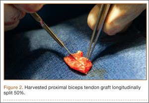
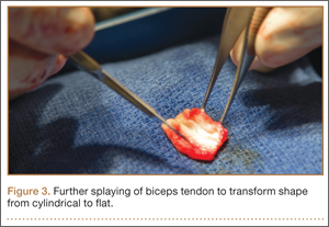
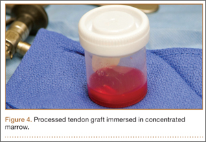
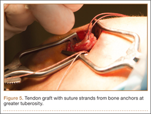
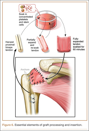
Results
Clinically, all patients improved with respect to pain, motion, strength, function, and satisfaction by virtue of the reconstructive surgery. After surgery, mean Constant score was increased, from 13 to 71 (P < .001). Mean ASES score increased from 18 to 75 (P < .001). Mean UCLA score increased from 4 to 28 (P < .001) (Table). Ultrasound showed 0% incidence of full-thickness retearing. Dynamic scanning during abduction showed maintained reduction of the humeral head within the glenoid socket; superior subluxation of the humeral head was not detected. The biceps tendon graft was continuous with the rotator cuff tendon, indicative of graft integration: tissue healing at the graft–bone and graft–tendon interfaces (Figures 7, 8). There were no intraoperative or postoperative patient-related complications.
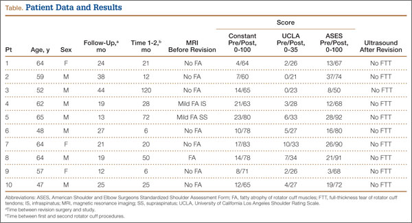
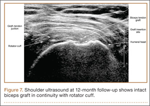
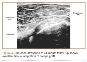
Discussion
Primary rotator cuff surgery is beneficial.5 Irrespective of technique, open versus arthroscopic,6 single- versus double-row repair,7 the clinical results have been satisfactory.8 Nevertheless, the “tissue failure” rate of rotator cuff surgery (full-thickness discontinuity of rotator cuff) has been as high as 31% in primary repairs.9 In revision rotator cuff repair and reconstruction, the radiographic tissue failure rate has been even higher, particularly in the setting of chronic large tears with retraction, with tissue failure rates up to 91%.10 Although small to medium full-thickness tears and retears are well tolerated by patients with reduced activity levels,11 and pain symptoms do not necessarily correlate with rotator cuff tear size,12 large retracted full-thickness tears in active patients seldom result in optimal clinical outcomes or patient satisfaction.13,14 In addition, although recurrent tearing does not preclude a satisfactory clinical result, maintenance of cuff tissue integrity tends to produce a better objective clinical score and a more desirable clinical outcome.2
Few evidence-based restorative solutions exist for large recurrent rotator cuff tears with retraction in active nongeriatric patients.15 The no-treatment option in this context may result in gradual enlargement of the tear, chronic pain, weakness, and progressive degeneration of the glenohumeral joint and acromiohumeral confluence—so-called rotator cuff arthropathy, for which reverse total shoulder arthroplasty is required.16,17 Partial repair of a large rotator cuff tear by margin convergence, interval slide, split deltoid flap, or nonanatomical reinsertion may improve clinical outcome scores but may not alter or prevent the progressive degenerative changes associated with rotator cuff arthropathy.18,19 Synthetic scaffolds with and without biological enhancement have been used with varying degrees of success, particularly pain improvement and tissue integration.20 Nevertheless, the failure rate has been reported to be 17% to 51%,21 and no evidence exists that allograft augmentation improves functional outcomes.22 Tendon transfer using the latissimus dorsi has also proved to be a surgical alternative in younger, active patients.23 However, dissection in this procedure is a major undertaking for both surgeon and patient—compared with the minimally invasive technique used in the present study.24
I selected a cohort of active, symptomatic patients for application of a synthesis of accepted surgical techniques through a mini-open incision in order to improve the reliability of the surgical construct while minimizing surgical morbidity. Débridement of marginal tissue, safe mobilization of remaining cuff, and tension-free suture line using locking sutures maximized the mechanical strength of the construct.25,26 Biological enhancement with autogenous tissue (the patient’s own biceps tendon) as graft material (scaffolding), as well as autologous concentrated marrow delivering viable responding cells and chemokine/cytokine biofactors, increased the probability of reparative activity at the graft site.27 The net effect was consistent tissue healing at a biologically challenging locus. Nonenhanced biceps tendon grafting in the setting of “irreparable” primary rotator cuff repair has had a 40-year history of orthopedic utility and an excellent record of clinical success.28 Nevertheless, the retear rate has been 7% to 30%.29 There are no previous reports of biologically enhanced autogenous biceps tendon grafting for reconstruction of a torn rotator cuff, either primary or in the setting of chronic revision surgery.
Previous well-designed PRP enhancement studies in the context of primary rotator cuff repair failed to demonstrate a consistent benefit with concentrated platelet-only augmentation.30,31 The shared experimental design of these published studies used intra-articular injection as the sole delivery method without guarantee that the injected platelets would migrate, adhere to, and persist at the intended destination, the healing edge of the rotator cuff. In the present study, extended exposure of the splayed tendon graft by incubation in concentrated marrow was specifically designed to increase the probability that biologically active components would settle at the desired location by cellular seeding and plasmatic imbibition.32 Furthermore, use of PRP for growth factor (platelet-derived, PDGF; basic fibroblast, bFGF; transforming, TGF-β; epidermal, EGF; vascular endothelial, VEGF; connective tissue, CTGF) therapy, in addition to pluripotential mesenchymal cells for marrow-derived stem cell therapy, is in theory biologically superior to use of PRP alone.33,34
The recent expansion of information about biologics has generated much interest in augmentation of soft-tissue healing. Unfortunately, the optimal technique of using cellular processing to upregulate stem-cell capacity at the graft interface is yet to be defined.35 Clinical studies using PRP and related products to promote tendon healing have been both inconsistent and contradictory with respect to benefit of outcome. As we have been unable to harness the biological potential of this medium, application of biologics in contemporary clinical orthopedics remains narrow, random, and infrequent. The technique presented in this clinical series appears to be a small advancement in a positive direction. The described construct provides a starting point for study, combining mechanical as well as biological steps to promote rotator cuff healing. The consistency of the outcome in a clinical model in which retearing is an expectation rather than an exception is noteworthy. The zero tissue failure rate at 1 to 4 years, compared with the literature values in similar patient cohorts, is very promising.36 The clinical outcome as measured by validated shoulder scores is also comparable to literature outcome values.19 Also noteworthy is the dynamic stability the construct gives to the glenohumeral joint. Ideally, the reconstructed rotator cuff provides active force coupling with the deltoid, simulating normal shoulder biomechanics. At a minimum, the reconstructed cuff provides a viable passive barrier to superior migration of the humeral head—thus supporting the mechanical efficiency of the deltoid and preventing rotator cuff arthropathy.
This study’s small sample (10 patients) puts its conclusions at risk for type I statistical error, in that too few patients were examined over a long enough period to demonstrate failure. Nevertheless, retears typically occur within 6 months of repair.37,38 Therefore, minimum follow-up of 1 year was deemed sufficient. None of the 10 patients had diabetes or another chronic comorbidity. Nine of the 10 had either no or only mild preoperative fatty atrophy of the rotator cuff muscles. Eight of the 10 were nonsmokers. These factors, which suggest optimal surgical candidates, may prove to be significant as the clinical series expands over time. Incubation of the autogenous biceps graft in concentrated marrow for 60 minutes was arbitrarily chosen. In future in vitro examination, marrow cell viability as a function of incubation time will be assessed.
Conclusion
In active, middle-aged patients with chronic recurrent large retracted rotator cuff tears, the technique presented here, using autogenous biceps tendon and autologous concentrated marrow containing PRP and mesenchymal cells, consistently yielded satisfactory clinical results and promoted rotator cuff tissue healing without full-thickness retearing.
1. Colvin AC, Egorova N, Harrison AK, Moskowitz A, Flatow EL. National trends in rotator cuff repair. J Bone Joint Surg Am. 2012;94(3):227-233.
2. Kim HM, Caldwell JM, Buza JA, et al. Factors affecting satisfaction and shoulder function in patients with a recurrent rotator cuff tear. J Bone Joint Surg Am. 2014;96(2):106-112.
3. George MS, Khazzam M. Current concepts review: revision rotator cuff repair. J Shoulder Elbow Surg. 2012;21(4):431-440.
4. Skoff HD. Conservative open acromioplasty. J Bone Joint Surg Br. 1995;77(6):933-936.
5. Mather RC 3rd, Koenig L, Acevedo D, et al. The societal and economic value of rotator cuff repair. J Bone Joint Surg Am. 2013;95(22):1993-2000.
6. Sauerbrey AM, Getz CL, Piancastelli M, Iannotti JP, Ramsey ML, Williams GR. Arthroscopic versus mini-open rotator cuff repair: a comparison of clinical outcome. Arthroscopy. 2005;21(12):1415-1420.
7. Koh KH, Kang KC, Lim TK, Shon MS, Yoo JC. Prospective randomized clinical trial of single- versus double-row suture anchor repair in 2- to 4-cm rotator cuff tears: clinical and magnetic resonance imaging results. Arthroscopy. 2011;27(4):453-462.
8. Galatz LM, Griggs S, Cameron BD, Iannotti JP. Prospective longitudinal analysis of post-operative shoulder function: a ten-year follow-up study of full thickness rotator cuff tears. J Bone Joint Surg Am. 2001;83(7):1052-1056.
9. Oh JH, Kim SH, Kang JY, Oh CH, Gong HS. Effect of age on functional and structural outcome after rotator cuff repair. Am J Sports Med. 2010;38(4):672-678.
10. Kim JH, Kim SH, Lee SK, Seo JW, Chun YMC. Arthroscopic repair of massive contracted rotator cuff tears: aggressive release with anterior and posterior interval slides do not improve cuff healing and integrity. J Bone Joint Surg Am. 2014;95(16):1482-1488.
11. Moosmayer S, Lund G, Seljom US, et al. Tendon repair compared with physiotherapy in the treatment of rotator cuff tears. J Bone Joint Surg Am. 2014;96(18):1504-1514.
12. Dunn WR, Kuhn JE, Sanders R, et al. Symptoms of pain do not correlate with rotator cuff tear severity. J Bone Joint Surg Am. 2014;96(10):793-800.
13. Lubiatowski P, Kaczmarek P, Dzianach M, et al. Clinical and biomechanical performance of patients with failed rotator cuff repair. Int Orthop. 2013;37(12):2395-2401.
14. Holtby R, Razmjou H. Relationship between clinical and surgical findings and reparability of large and massive rotator cuff tears: a longitudinal study. BMC Musculoskelet Disord. 2014;15:180.
15. Nho SJ, Delos D, Yadav H, et al. Biomechanical and biological augmentation for the treatment of massive rotator cuff tears. Am J Sports Med. 2010;38(3):619-629.
16. Moosmayer S, Tariq R, Stiris M, Smith HJ. The natural history of asymptomatic rotator cuff tears: a three-year follow-up of fifty cases. J Bone Joint Surg Am. 2013;95(14):1249-1255.
17. Neer CS 2nd, Craig EV, Fukuda H. Cuff-tear arthropathy. J Bone Joint Surg Am. 1983;65(9):1232-1244.
18. Bartl C, Louloumentas P, Konstantin H, et al. Long-term outcome and structural integrity following open repair of massive rotator cuff tears. Int J Shoulder Surg. 2012;6(1):1-8.
19. Paxton ES, Teefey SA, Dahiya N, Keener JD, Yamaguchi K, Galatz LM. Clinical and radiographic outcomes of failed repairs of large or massive rotator cuff tears: minimum ten-year follow-up. J Bone Joint Surg Am. 2013;95(7):627-632.
20. Longo UG, Lamberti A, Maffulli N, Denaro V. Tendon augmentation grafts: a systematic review. Br Med Bull. 2010;94:165-188.
21. Ciampi P, Scotti C, Nonis A, et al. The benefit of synthetic versus biological patch augmentation in the repair of posterosuperior massive rotator cuff tears: a 3-year follow-up study. Am J Sports Med. 2014;42(5):1169-1175.
22. Murhi AM. Rotator cuff tears and cuff tear arthropathy. In: Boyer MI, ed. AAOS Comprehensive Orthopedic Review. Vol 2. Rosemont, IL: American Academy of Orthopaedic Surgeons; 2014:921-929.
23. Namdari S, Voleti P, Baldwin K, Glaser D, Huffman GR. Latissimus dorsi tendon transfer for irreparable rotator cuff tears: a systematic review. J Bone Joint Surg Am. 2012;94(10):891-898.
24. Gerber C, Rahm SA, Catanzaro S, Farshad M, Moor BK. Latissimus dorsi tendon transfer for treatment of irreparable posterosuperior rotator cuff tears: long-term results at a minimum follow-up of ten years. J Bone Joint Surg Am. 2013;95(21):1920-1926.
25. Wagner JP, Krushall RJ, Masqueloet A, Gerber C. Anatomy and relationships of the suprascapular nerve: anatomical constraints to mobilization of the supraspinatus and infraspinatus muscles in the management of massive rotator cuff tears. J Bone Joint Surg Am. 1992;74(1):36-45.
26. Ponce BA, Hosemann CD, Reghava P, Tate JP, Sheppard ED, Ebenhardt AW. A biomechanical analysis of controllable intraoperative variables affecting the strength of rotator cuff repairs at the suture–tendon interface. Am J Sports Med. 2013;41(10):2256-2261.
27. Thomopoulos S. Tendon and ligaments. In: Boyer MI, ed. AAOS Comprehensive Orthopedic Review. Vol 2. Rosemont, IL: American Academy of Orthopaedic Surgeons; 2014:105-111.
28. Sano H, Mineta M, Kitz A, Itoi E. Tendon patch grafting using the long head of the biceps for irreparable massive rotator cuff tears. J Orthop Sci. 2010;15(3):310-316.
29. Rhee YG, Cho NS, Lim CT, Yi JW, Vishvanathan T. Bridging the gap in immobile massive rotator cuff tears: augmentation using the tenotomized biceps. Am J Sports Med. 2008;36(8):1511-1518.
30. Castricini R, Longo UG, De Benedetto M, et al. Platelet-rich plasma augmentation for arthroscopic rotator cuff repair: a randomized controlled trial. Am J Sports Med. 2011;39(2):258-265.
31. Rodeo SA, Delos, D, Williams, RJ, Adler RS, Pearle A, Warren RF. The effects of platelet-rich fibrin matrix on rotator cuff tendon healing: a prospective, randomized clinical study. Am J Sports Med. 2012;40(6):1234-1241.
32. Beitzel K, McCarthy MB, Cote MP, et al. Properties of biologic scaffolds and their response to mesenchymal stem cells. Arthroscopy. 2014;30(3):289-298.
33. Anz AW, Hackel JG, Nilssen ED, Andrews JR. Application of biologics in the treatment of rotator cuff, meniscus, cartilage and osteoarthritis. J Am Acad Orthop Surg. 2014;22(2):68-79.
34. Hernigou P, Flouzat Lachaniette CH, Delambre J, et al. Biologic augmentation of rotator cuff repair with mesenchymal stem cells during arthroscopy improves healing and prevents further tears: a case-controlled study. Int Orthop. 2014;38(9):1811-1818.
35. Hsu WK, Mishra A, Rodeo SR, et al. Platelet-rich plasma in orthopaedic applications: evidence-based recommendations for treatment. J Am Acad Orthop Surg. 2013;21(12):739-748.
36. Kowalsky MS, Keener JD. Revision arthroscopic rotator cuff repair: repair integrity and clinical outcome: surgical technique. J Bone Joint Surg Am. 2011;93(suppl 1):62-74.
37. Iannotti JP, Deutsch A, Green A, et al. Time to failure after rotator cuff repair: a prospective imaging study. J Bone Joint Surg Am. 2013;95(11):965-971.
38. Le BT, Wu XL, Lam PH, Murrell GA. Factors predicting rotator cuff retears: an analysis of 1000 consecutive rotator cuff repairs. Am J Sports Med. 2014;42(5):1134-1142.
Primary rotator cuff repair is a common procedure that consistently yields favorable clinical results.1 Revision rotator cuff repair and reconstruction yield less consistent clinical results and are associated with a significant incidence of recurrent cuff tearing.2 Possible factors contributing to the loss of tissue continuity have included poor quality or frank loss of rotator cuff tissue, diminished biological potential of the rotator cuff tendon, and excessive mechanical stress on or strain of the reconstructive surgical construct.3
I conducted a pilot study involving a technique that addresses these potential factors, amalgamating several contemporary surgical methods with the addition of a novel step: an autogenous tendon graft incubated in autologous bone marrow concentrate.
Materials and Methods
Ten consecutive patients (7 men, 3 women) enrolled in this retrospective case series. Mean age at time of surgery was 58 years (range, 47-65 years). Mean follow-up was 24 months (range, 12-44 months), and no patients were lost to follow-up. Mean time between original primary repair and current reconstruction was 36 months (range, 6-120 months). Criteria for enrollment included unremitting shoulder pain, radiographs showing no significant degenerative joint disease, magnetic resonance imaging confirming a large (3-5 cm) full-thickness rotator cuff tear with retraction, and history of prior rotator cuff repair on the affected shoulder without associated biceps tenodesis. The intraoperative inclusion criterion was direct visualization of a 3- to 5-cm full-thickness rotator cuff tear with retraction of at least 3 cm. Validated Constant, American Shoulder and Elbow Surgeons (ASES), and University of California Los Angeles (UCLA) shoulder scoring systems were used to collect range-of-motion, pain, strength, daily function, and patient satisfaction data before and after surgery. Standard error was calculated. Two-sample t test was used for preoperative–postoperative comparisons. Postoperative integrity of the rotator cuff reconstruction was evaluated by an independent full-time academic musculoskeletal radiologist using dynamic diagnostic ultrasound (iU22 xMatrix Ultrasound System [Philips Healthcare] at L 9-3 MHz). Informed consent was obtained from each patient. The study was approved by institutional review board.
After induction of general anesthesia, each patient was placed in the lateral decubitus position. Bone marrow (60 mL) was aspirated through a 14-gauge needle from a dorsal iliac table, just inferior to the iliac crest (Figure 1). The patient was then placed into the beach-chair position on a surgical shoulder table. The aspirated marrow was centrifuged at 2800 and 3800 rpm for 14 to 17 minutes (Magellan Autologous Platelet Separator; Arteriocyte Medical Systems) to yield 10 mL of a concentrated (4- to 5-fold) mixture of platelet-rich plasma (PRP) and mesenchymal stem cells. Surgery was performed through a 3-cm oblique anterior mini-open incision between the anterior corner of the acromion and the coracoid process, as I previously described.4 The deltoid muscle was split, not detached. Acromioplasty and release of the coracoacromial ligament were performed. The rotator cuff was inspected under ×4.5 optical magnification. The cuff tissue was mobilized and débrided back to a healthy-appearing margin. The size and shape of the rotator cuff defect were then estimated. The long head of the biceps was harvested from its origin just distal to the superior glenoid labrum unto the intertubercular sulcus on the proximal humerus. The remainder of the biceps tendon was tenodesed to the surgical neck of the humerus. The biceps tendon graft was then manipulated and fashioned (by longitudinal partial-thickness incision and expansion) to fit the cuff defect (Figures 2, 3). The expanded graft was incubated in the concentrated marrow (10 mL) for 60 minutes (Figure 4). Débridement at the base of the greater tuberosity down to bleeding cancellous bone was followed by insertion of multiple bone anchors bearing several strands of No. 2 synthetic suture. These strands were then passed through the biceps tendon graft for secure fixation (Figure 5). The débrided end of the rotator cuff was then sewn to the biceps tendon graft using locking stitches under zero tissue tension with the arm in full adduction. The free end of the graft was sewn to the subscapularis tendon (Figure 6). The remaining marrow concentrate was injected both deep and superficial to the rotator cuff construct. No additional wound irrigation fluid was injected or suction drain inserted. After surgery, the patient was placed into an abduction pillow for 1 month and then engaged in passive motion for 1 month. Active-assisted motion began 3 months after surgery.
Results
Clinically, all patients improved with respect to pain, motion, strength, function, and satisfaction by virtue of the reconstructive surgery. After surgery, mean Constant score was increased, from 13 to 71 (P < .001). Mean ASES score increased from 18 to 75 (P < .001). Mean UCLA score increased from 4 to 28 (P < .001) (Table). Ultrasound showed 0% incidence of full-thickness retearing. Dynamic scanning during abduction showed maintained reduction of the humeral head within the glenoid socket; superior subluxation of the humeral head was not detected. The biceps tendon graft was continuous with the rotator cuff tendon, indicative of graft integration: tissue healing at the graft–bone and graft–tendon interfaces (Figures 7, 8). There were no intraoperative or postoperative patient-related complications.
Discussion
Primary rotator cuff surgery is beneficial.5 Irrespective of technique, open versus arthroscopic,6 single- versus double-row repair,7 the clinical results have been satisfactory.8 Nevertheless, the “tissue failure” rate of rotator cuff surgery (full-thickness discontinuity of rotator cuff) has been as high as 31% in primary repairs.9 In revision rotator cuff repair and reconstruction, the radiographic tissue failure rate has been even higher, particularly in the setting of chronic large tears with retraction, with tissue failure rates up to 91%.10 Although small to medium full-thickness tears and retears are well tolerated by patients with reduced activity levels,11 and pain symptoms do not necessarily correlate with rotator cuff tear size,12 large retracted full-thickness tears in active patients seldom result in optimal clinical outcomes or patient satisfaction.13,14 In addition, although recurrent tearing does not preclude a satisfactory clinical result, maintenance of cuff tissue integrity tends to produce a better objective clinical score and a more desirable clinical outcome.2
Few evidence-based restorative solutions exist for large recurrent rotator cuff tears with retraction in active nongeriatric patients.15 The no-treatment option in this context may result in gradual enlargement of the tear, chronic pain, weakness, and progressive degeneration of the glenohumeral joint and acromiohumeral confluence—so-called rotator cuff arthropathy, for which reverse total shoulder arthroplasty is required.16,17 Partial repair of a large rotator cuff tear by margin convergence, interval slide, split deltoid flap, or nonanatomical reinsertion may improve clinical outcome scores but may not alter or prevent the progressive degenerative changes associated with rotator cuff arthropathy.18,19 Synthetic scaffolds with and without biological enhancement have been used with varying degrees of success, particularly pain improvement and tissue integration.20 Nevertheless, the failure rate has been reported to be 17% to 51%,21 and no evidence exists that allograft augmentation improves functional outcomes.22 Tendon transfer using the latissimus dorsi has also proved to be a surgical alternative in younger, active patients.23 However, dissection in this procedure is a major undertaking for both surgeon and patient—compared with the minimally invasive technique used in the present study.24
I selected a cohort of active, symptomatic patients for application of a synthesis of accepted surgical techniques through a mini-open incision in order to improve the reliability of the surgical construct while minimizing surgical morbidity. Débridement of marginal tissue, safe mobilization of remaining cuff, and tension-free suture line using locking sutures maximized the mechanical strength of the construct.25,26 Biological enhancement with autogenous tissue (the patient’s own biceps tendon) as graft material (scaffolding), as well as autologous concentrated marrow delivering viable responding cells and chemokine/cytokine biofactors, increased the probability of reparative activity at the graft site.27 The net effect was consistent tissue healing at a biologically challenging locus. Nonenhanced biceps tendon grafting in the setting of “irreparable” primary rotator cuff repair has had a 40-year history of orthopedic utility and an excellent record of clinical success.28 Nevertheless, the retear rate has been 7% to 30%.29 There are no previous reports of biologically enhanced autogenous biceps tendon grafting for reconstruction of a torn rotator cuff, either primary or in the setting of chronic revision surgery.
Previous well-designed PRP enhancement studies in the context of primary rotator cuff repair failed to demonstrate a consistent benefit with concentrated platelet-only augmentation.30,31 The shared experimental design of these published studies used intra-articular injection as the sole delivery method without guarantee that the injected platelets would migrate, adhere to, and persist at the intended destination, the healing edge of the rotator cuff. In the present study, extended exposure of the splayed tendon graft by incubation in concentrated marrow was specifically designed to increase the probability that biologically active components would settle at the desired location by cellular seeding and plasmatic imbibition.32 Furthermore, use of PRP for growth factor (platelet-derived, PDGF; basic fibroblast, bFGF; transforming, TGF-β; epidermal, EGF; vascular endothelial, VEGF; connective tissue, CTGF) therapy, in addition to pluripotential mesenchymal cells for marrow-derived stem cell therapy, is in theory biologically superior to use of PRP alone.33,34
The recent expansion of information about biologics has generated much interest in augmentation of soft-tissue healing. Unfortunately, the optimal technique of using cellular processing to upregulate stem-cell capacity at the graft interface is yet to be defined.35 Clinical studies using PRP and related products to promote tendon healing have been both inconsistent and contradictory with respect to benefit of outcome. As we have been unable to harness the biological potential of this medium, application of biologics in contemporary clinical orthopedics remains narrow, random, and infrequent. The technique presented in this clinical series appears to be a small advancement in a positive direction. The described construct provides a starting point for study, combining mechanical as well as biological steps to promote rotator cuff healing. The consistency of the outcome in a clinical model in which retearing is an expectation rather than an exception is noteworthy. The zero tissue failure rate at 1 to 4 years, compared with the literature values in similar patient cohorts, is very promising.36 The clinical outcome as measured by validated shoulder scores is also comparable to literature outcome values.19 Also noteworthy is the dynamic stability the construct gives to the glenohumeral joint. Ideally, the reconstructed rotator cuff provides active force coupling with the deltoid, simulating normal shoulder biomechanics. At a minimum, the reconstructed cuff provides a viable passive barrier to superior migration of the humeral head—thus supporting the mechanical efficiency of the deltoid and preventing rotator cuff arthropathy.
This study’s small sample (10 patients) puts its conclusions at risk for type I statistical error, in that too few patients were examined over a long enough period to demonstrate failure. Nevertheless, retears typically occur within 6 months of repair.37,38 Therefore, minimum follow-up of 1 year was deemed sufficient. None of the 10 patients had diabetes or another chronic comorbidity. Nine of the 10 had either no or only mild preoperative fatty atrophy of the rotator cuff muscles. Eight of the 10 were nonsmokers. These factors, which suggest optimal surgical candidates, may prove to be significant as the clinical series expands over time. Incubation of the autogenous biceps graft in concentrated marrow for 60 minutes was arbitrarily chosen. In future in vitro examination, marrow cell viability as a function of incubation time will be assessed.
Conclusion
In active, middle-aged patients with chronic recurrent large retracted rotator cuff tears, the technique presented here, using autogenous biceps tendon and autologous concentrated marrow containing PRP and mesenchymal cells, consistently yielded satisfactory clinical results and promoted rotator cuff tissue healing without full-thickness retearing.
1. Colvin AC, Egorova N, Harrison AK, Moskowitz A, Flatow EL. National trends in rotator cuff repair. J Bone Joint Surg Am. 2012;94(3):227-233.
2. Kim HM, Caldwell JM, Buza JA, et al. Factors affecting satisfaction and shoulder function in patients with a recurrent rotator cuff tear. J Bone Joint Surg Am. 2014;96(2):106-112.
3. George MS, Khazzam M. Current concepts review: revision rotator cuff repair. J Shoulder Elbow Surg. 2012;21(4):431-440.
4. Skoff HD. Conservative open acromioplasty. J Bone Joint Surg Br. 1995;77(6):933-936.
5. Mather RC 3rd, Koenig L, Acevedo D, et al. The societal and economic value of rotator cuff repair. J Bone Joint Surg Am. 2013;95(22):1993-2000.
6. Sauerbrey AM, Getz CL, Piancastelli M, Iannotti JP, Ramsey ML, Williams GR. Arthroscopic versus mini-open rotator cuff repair: a comparison of clinical outcome. Arthroscopy. 2005;21(12):1415-1420.
7. Koh KH, Kang KC, Lim TK, Shon MS, Yoo JC. Prospective randomized clinical trial of single- versus double-row suture anchor repair in 2- to 4-cm rotator cuff tears: clinical and magnetic resonance imaging results. Arthroscopy. 2011;27(4):453-462.
8. Galatz LM, Griggs S, Cameron BD, Iannotti JP. Prospective longitudinal analysis of post-operative shoulder function: a ten-year follow-up study of full thickness rotator cuff tears. J Bone Joint Surg Am. 2001;83(7):1052-1056.
9. Oh JH, Kim SH, Kang JY, Oh CH, Gong HS. Effect of age on functional and structural outcome after rotator cuff repair. Am J Sports Med. 2010;38(4):672-678.
10. Kim JH, Kim SH, Lee SK, Seo JW, Chun YMC. Arthroscopic repair of massive contracted rotator cuff tears: aggressive release with anterior and posterior interval slides do not improve cuff healing and integrity. J Bone Joint Surg Am. 2014;95(16):1482-1488.
11. Moosmayer S, Lund G, Seljom US, et al. Tendon repair compared with physiotherapy in the treatment of rotator cuff tears. J Bone Joint Surg Am. 2014;96(18):1504-1514.
12. Dunn WR, Kuhn JE, Sanders R, et al. Symptoms of pain do not correlate with rotator cuff tear severity. J Bone Joint Surg Am. 2014;96(10):793-800.
13. Lubiatowski P, Kaczmarek P, Dzianach M, et al. Clinical and biomechanical performance of patients with failed rotator cuff repair. Int Orthop. 2013;37(12):2395-2401.
14. Holtby R, Razmjou H. Relationship between clinical and surgical findings and reparability of large and massive rotator cuff tears: a longitudinal study. BMC Musculoskelet Disord. 2014;15:180.
15. Nho SJ, Delos D, Yadav H, et al. Biomechanical and biological augmentation for the treatment of massive rotator cuff tears. Am J Sports Med. 2010;38(3):619-629.
16. Moosmayer S, Tariq R, Stiris M, Smith HJ. The natural history of asymptomatic rotator cuff tears: a three-year follow-up of fifty cases. J Bone Joint Surg Am. 2013;95(14):1249-1255.
17. Neer CS 2nd, Craig EV, Fukuda H. Cuff-tear arthropathy. J Bone Joint Surg Am. 1983;65(9):1232-1244.
18. Bartl C, Louloumentas P, Konstantin H, et al. Long-term outcome and structural integrity following open repair of massive rotator cuff tears. Int J Shoulder Surg. 2012;6(1):1-8.
19. Paxton ES, Teefey SA, Dahiya N, Keener JD, Yamaguchi K, Galatz LM. Clinical and radiographic outcomes of failed repairs of large or massive rotator cuff tears: minimum ten-year follow-up. J Bone Joint Surg Am. 2013;95(7):627-632.
20. Longo UG, Lamberti A, Maffulli N, Denaro V. Tendon augmentation grafts: a systematic review. Br Med Bull. 2010;94:165-188.
21. Ciampi P, Scotti C, Nonis A, et al. The benefit of synthetic versus biological patch augmentation in the repair of posterosuperior massive rotator cuff tears: a 3-year follow-up study. Am J Sports Med. 2014;42(5):1169-1175.
22. Murhi AM. Rotator cuff tears and cuff tear arthropathy. In: Boyer MI, ed. AAOS Comprehensive Orthopedic Review. Vol 2. Rosemont, IL: American Academy of Orthopaedic Surgeons; 2014:921-929.
23. Namdari S, Voleti P, Baldwin K, Glaser D, Huffman GR. Latissimus dorsi tendon transfer for irreparable rotator cuff tears: a systematic review. J Bone Joint Surg Am. 2012;94(10):891-898.
24. Gerber C, Rahm SA, Catanzaro S, Farshad M, Moor BK. Latissimus dorsi tendon transfer for treatment of irreparable posterosuperior rotator cuff tears: long-term results at a minimum follow-up of ten years. J Bone Joint Surg Am. 2013;95(21):1920-1926.
25. Wagner JP, Krushall RJ, Masqueloet A, Gerber C. Anatomy and relationships of the suprascapular nerve: anatomical constraints to mobilization of the supraspinatus and infraspinatus muscles in the management of massive rotator cuff tears. J Bone Joint Surg Am. 1992;74(1):36-45.
26. Ponce BA, Hosemann CD, Reghava P, Tate JP, Sheppard ED, Ebenhardt AW. A biomechanical analysis of controllable intraoperative variables affecting the strength of rotator cuff repairs at the suture–tendon interface. Am J Sports Med. 2013;41(10):2256-2261.
27. Thomopoulos S. Tendon and ligaments. In: Boyer MI, ed. AAOS Comprehensive Orthopedic Review. Vol 2. Rosemont, IL: American Academy of Orthopaedic Surgeons; 2014:105-111.
28. Sano H, Mineta M, Kitz A, Itoi E. Tendon patch grafting using the long head of the biceps for irreparable massive rotator cuff tears. J Orthop Sci. 2010;15(3):310-316.
29. Rhee YG, Cho NS, Lim CT, Yi JW, Vishvanathan T. Bridging the gap in immobile massive rotator cuff tears: augmentation using the tenotomized biceps. Am J Sports Med. 2008;36(8):1511-1518.
30. Castricini R, Longo UG, De Benedetto M, et al. Platelet-rich plasma augmentation for arthroscopic rotator cuff repair: a randomized controlled trial. Am J Sports Med. 2011;39(2):258-265.
31. Rodeo SA, Delos, D, Williams, RJ, Adler RS, Pearle A, Warren RF. The effects of platelet-rich fibrin matrix on rotator cuff tendon healing: a prospective, randomized clinical study. Am J Sports Med. 2012;40(6):1234-1241.
32. Beitzel K, McCarthy MB, Cote MP, et al. Properties of biologic scaffolds and their response to mesenchymal stem cells. Arthroscopy. 2014;30(3):289-298.
33. Anz AW, Hackel JG, Nilssen ED, Andrews JR. Application of biologics in the treatment of rotator cuff, meniscus, cartilage and osteoarthritis. J Am Acad Orthop Surg. 2014;22(2):68-79.
34. Hernigou P, Flouzat Lachaniette CH, Delambre J, et al. Biologic augmentation of rotator cuff repair with mesenchymal stem cells during arthroscopy improves healing and prevents further tears: a case-controlled study. Int Orthop. 2014;38(9):1811-1818.
35. Hsu WK, Mishra A, Rodeo SR, et al. Platelet-rich plasma in orthopaedic applications: evidence-based recommendations for treatment. J Am Acad Orthop Surg. 2013;21(12):739-748.
36. Kowalsky MS, Keener JD. Revision arthroscopic rotator cuff repair: repair integrity and clinical outcome: surgical technique. J Bone Joint Surg Am. 2011;93(suppl 1):62-74.
37. Iannotti JP, Deutsch A, Green A, et al. Time to failure after rotator cuff repair: a prospective imaging study. J Bone Joint Surg Am. 2013;95(11):965-971.
38. Le BT, Wu XL, Lam PH, Murrell GA. Factors predicting rotator cuff retears: an analysis of 1000 consecutive rotator cuff repairs. Am J Sports Med. 2014;42(5):1134-1142.